1970 (California), 1971 (elsewhere) and 1972
Hover over a number for the key, click on the menu items below to show the vapour/vacuum routings.
Fuel Flow Tank Expansion/Contraction Carb Expansion Crankcase Breathing
Image from the British Leyland Workshop Manual
Fuel is sucked from the bottom of the tank (1) by the pump (12) and pushed through the fuel filter (13) and into the carb float chambers.
The main drawing is 'generic', it's the inset that is applicable to the MGB with the separation tank (7) and capacity limiting chamber (17). The capacity limiting chamber only fills very slowly, the filling station pump shuts off when fuel reaches the filler neck and the chamber is still largely full of air. That air bleeds out slowly via the separation tank to the charcoal canister (8) and to atmosphere (11). As it does so the fuel level rises in the chamber so lowering the level in the main part of the tank. This prevents fuel expansion while in the tank from overflowing (as it can do from the filler on a hot day just after being filled without this system) via the charcoal canister. Any fuel that does reach the separation chamber e.g. from rapid cornering drains back into the tank from the lower port on the separation chamber when cornering forces subside. A sealed filler cap is used with this system.
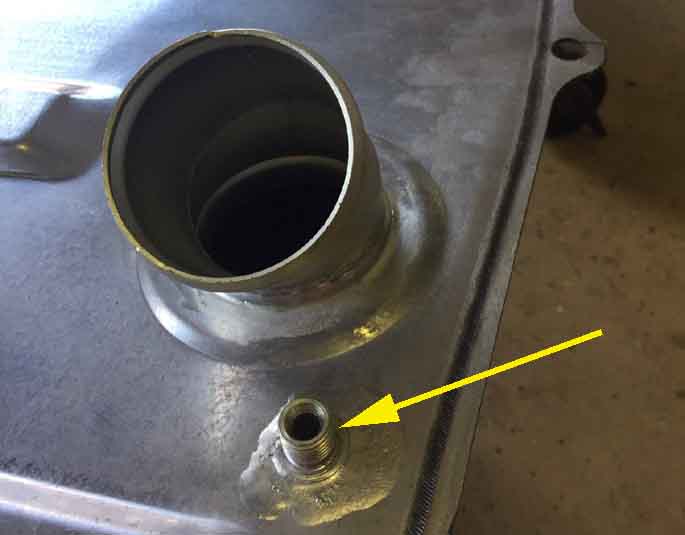
'A' allows fuel in and out of the capacity limiting chamber freely, but fuel can only get in as air escapes slowly via the narrow pipe 'B' which is connected to an external vent port. This vent port and pipe also allows air to enter as fuel is used in running: (Grassroots Motorsports)
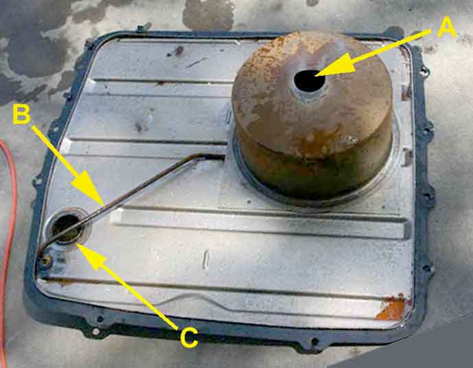
Tank vent connected via separation chamber to charcoal canister: (Bill Etter)
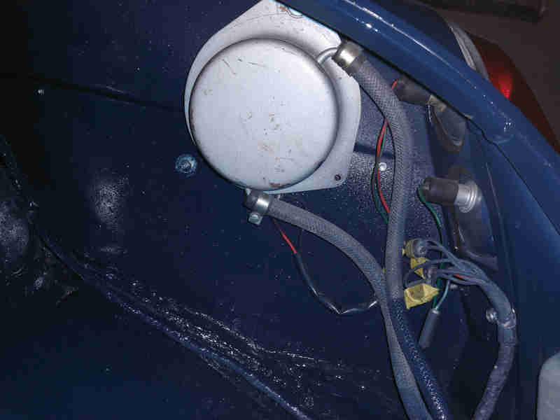
Pictures of the separation chamber on Bill Etter's 1970:
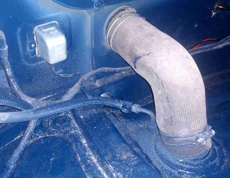
Connection from the top of the separation chamber through the boot floor to the pipe leading to the charcoal canister:
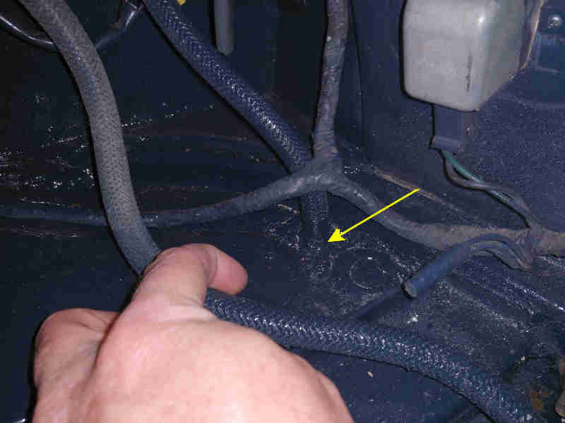
And to the tank vent: