
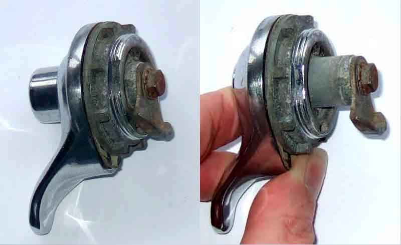
Push button in the closed (left) and open (right) positions.
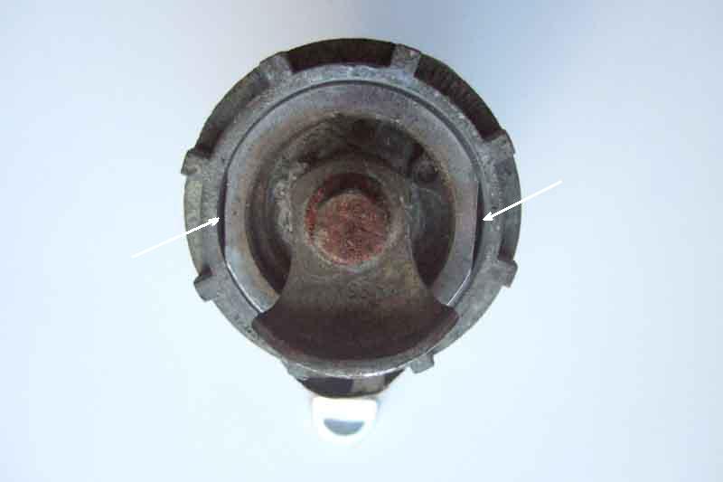
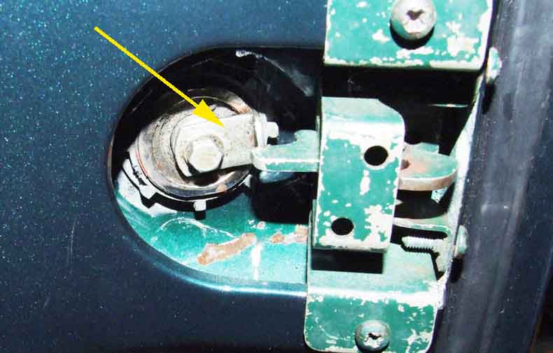
Showing the flats on the lock body (arrowed) that engage with corresponding flats in the panel to prevent the latch twisting very far. It's possible that the lid flats could be worn away, or missing altogether in some replacement units, allowing the lock to twist much more than usual.
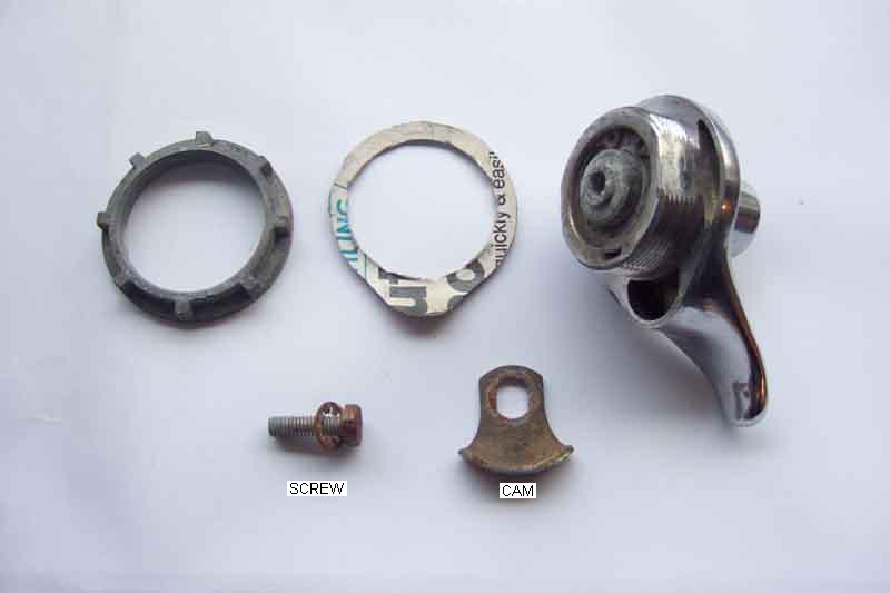
Dismantled push button showing the screw and cam that come loose. There should be a fibre gasket or washer between the push button and the boot lid, the one here is home made by a PO but the correct part is AHH 6180. This prevents water ingress as well as scratching of the paint if the release twists a little in use. The cam and the lock barrel also have flats to keep the relative positions of cam and lock consistent, as it is the cam that rotates though 90 degrees as the key is turned that determines whether the button will release the latch or not.
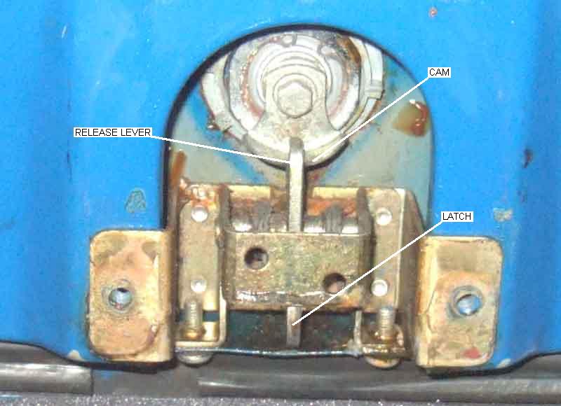
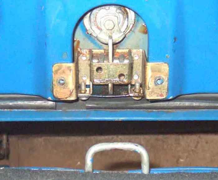
Showing the fitted push button in the locked position and the cam clear of the release lever. The latch engages with the bar that is bolted to the rear panel. This is from a GT.
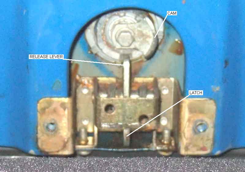
The fitted push button in the unlocked position and the cam aligned with the release lever.
Push button in the unlocked and closed position (tailgate open for clarity). When fully closed the latch would be hooked under the bar on the rear panel.
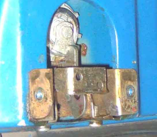
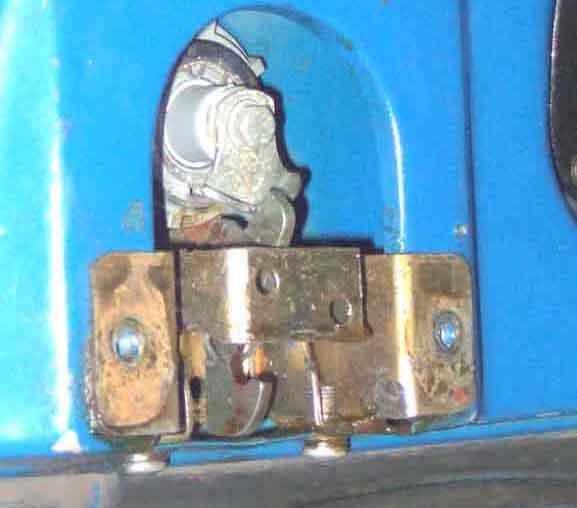
Push button operated, release lever pushed forwards, and the latch pushed back to clear the bar.
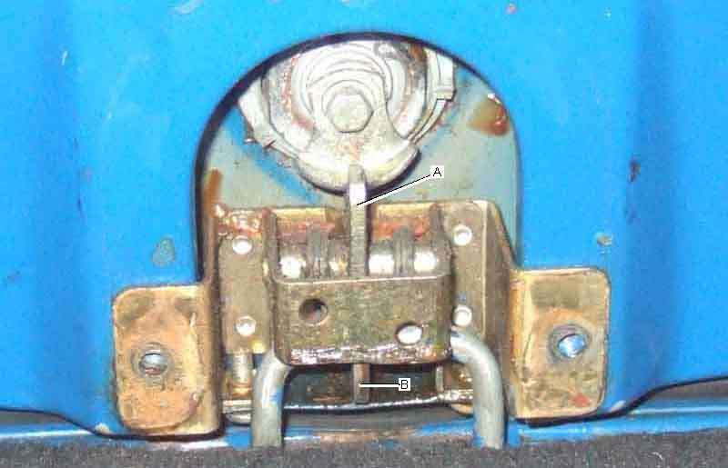
Hatch closed with the latch hooked under the bar. To release the lock from the inside either point A must be pulled forwards (towards the front of the car) or point B pushed backwards. On a GT a piece of wood of cross-section up to 3/4" high and 1 1/2" wide (to fit through the loop in the bar) can be used to push point B and surprisingly little pressure is required to release it.
My longer cam on the right, with the shorter cam on the left built up by 1/4" to match the longer cam plus the additional gap between the lock and the latch on Chris's car.
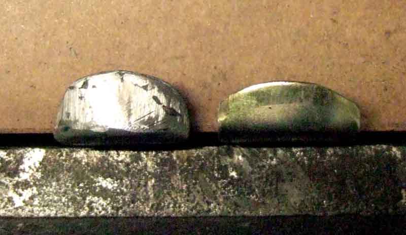
Roger Parker's cam, significantly narrower than either of mine, and if loose more likely to fail to properly engage with the latch lever.
Latch Striker:
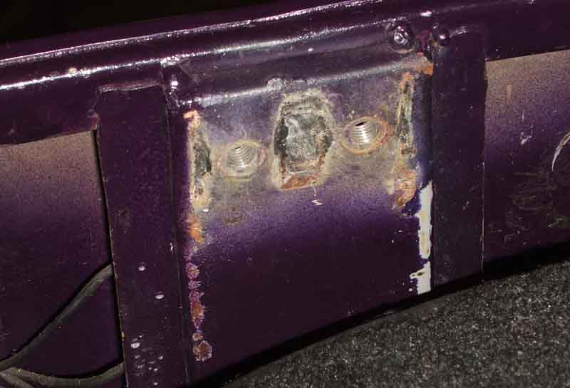
The strut on the rear panel that the striker attaches to, with welded nuts on the back.
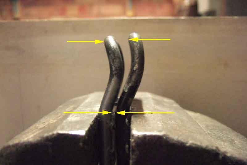
Comparing two strikers or latch bars. Consider the spacing between the bars by the mounting plate (lower arrows) with that at the point the latch engages (upper arrows). The rear panel that the striker is mounted on would be on the left, meaning that the top of the striker on the left (the faulty one) would be about 1/4" further back than the one on the right (the good one).
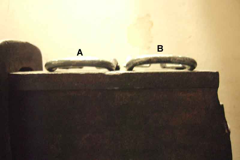
Also note how flat the top of the bar at A (the good one) is compared to the bow in B. This bow puts the bar even further out of alignment with the latch.
Original slots (left) cut through with an angle grinder (right) to allow the striker to sit higher with the seals that are currently available ...
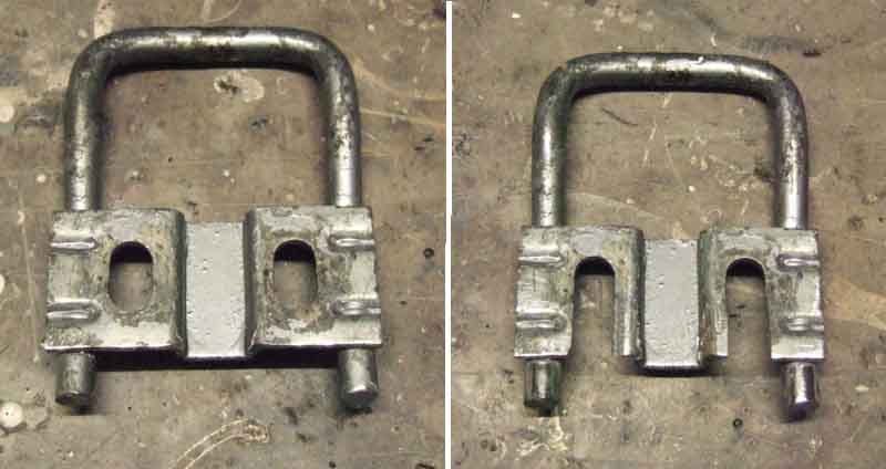
... and strip welded across the bottom (left) compared with an original (right).
