
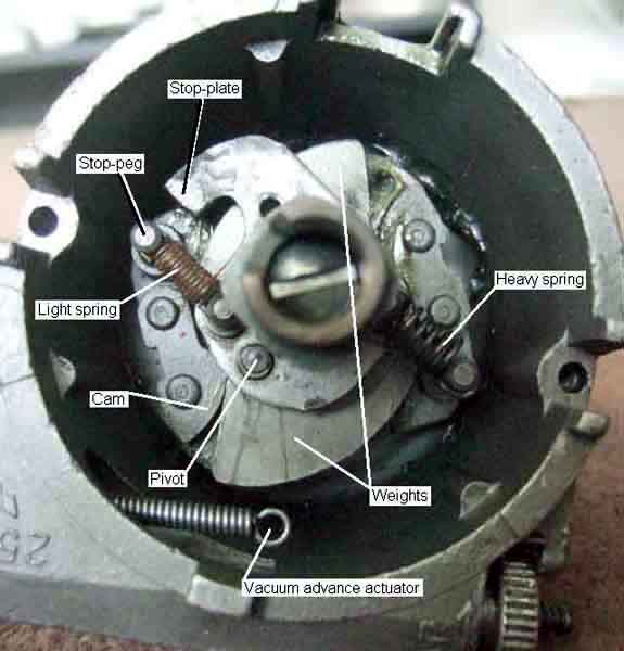
A general view of a 25D distributor and what lies beneath the points plate.
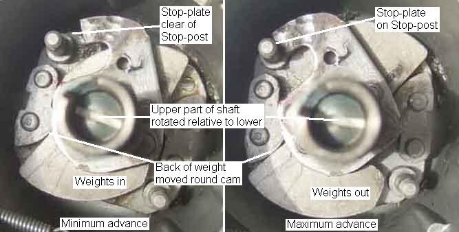
As the weights move out the back of the weights roll round the cam faces and this has the effect of pushing the weight pivot forwards, so twisting the upper part of the distributor shaft (carrying the points cam and rotor) anti-clockwise relative to the lower half of the shaft, so advancing the timing. Sometimes different weights are used for different curves, but often the weights will be common to many distributors and the curve controlled solely by the springs. The upper part of the distributor shaft contains the stop-plate and each one is machined to a specific length to give a specific maximum advance setting, stamped in distributor degrees (ground off by the rebuilder in this case in an attempt to hide the fact it is the wrong stop-plate for this reference number!).
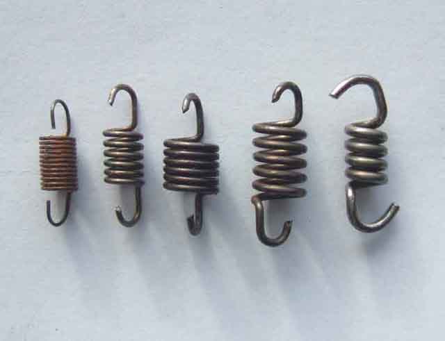
A selection of springs. Note the difference in overall length as well as wire thickness, coil diameter and number of turns. Shorter and thinner springs are generally used to give the initial rapid increase in advance in the first part of the curve, longer and thicker springs being used to give the second, flatter part of the curve.
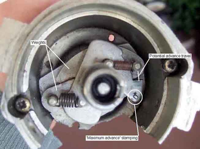
A general view of what lies under a typical 45D points plate, this distributor has had part of the body cut away for test purposes. This shows a 10 (distributor) degree maximum advance stop-plate, the stamping being a bit close to the edge. The 45D centrifugal advance mechanism takes up less space than the 25D, so the body of the distributor can be smaller. This makes it slightly easier to remove the distributor complete with clamping plate, which means on re-insertion the timing is usually close enough to get the engine started and perform dynamic timing rather than static time first before it can be started. It also avoids re-tightening the clamp-plate bolt, which most people over-tighten, which can damage the shoulder of the distributor and cause it to jump out of engagement.
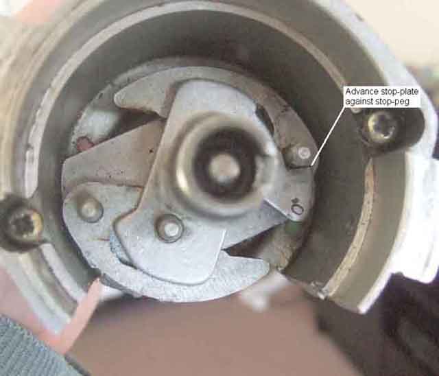
Maximum centrifugal advance, stop-plate against stop-peg.
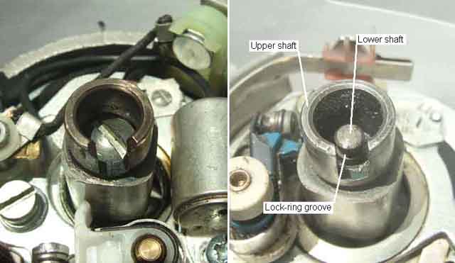
The next bit shows the upper part of the shaft having been removed from the distributor. To just get at the springs this isn't required, but if you do decide to remove it, a warning: Unlike the 25D which has a screw holding the upper half of the shaft to the lower (on the left in this picture), the 45D has just a plastic lock-ring sitting in a groove in the top of the lower shaft (on the right). On the 45D the two have to be forced apart, which can damage the lock-ring. Don't be tempted to re-install the distributor to an engine without some means of securing the upper and lower shafts back together or you could destroy the distributor if the upper half of the shaft jumps up. A stack of washers (to take up some of the space the lock-ring occupied) and a circlip of a suitable size should be OK.
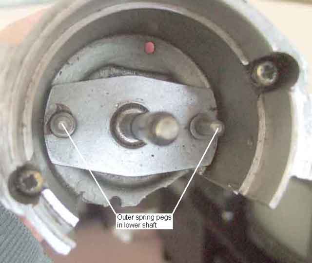
The bare bones of the lower half of the shaft.
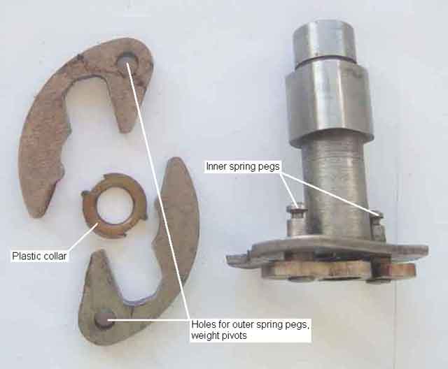
The upper half of the shaft, plastic collar and weights.
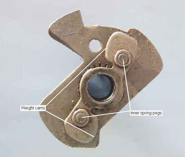
The bottom of the upper half of the shaft, showing the cams the weights act against.
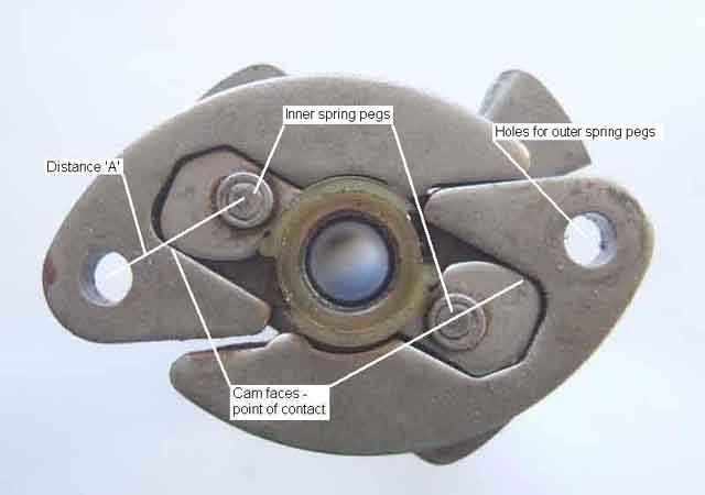
Minimum advance, showing the point of contact between weights and cams, and the distance between the pegs the springs are mounted on. The pegs of the lower half of the shaft go through the holes in the weights and are what the weights pivot on. Note the collar has two pairs of slots but only one of them will comfortably fit over the cam plate.
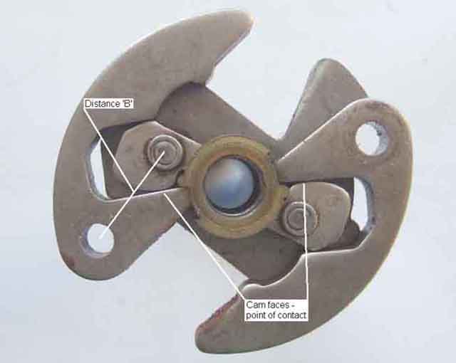
Maximum advance, showing the weights having rolled round the faces of the cams as they fly out. Distance B has increased from distance A. The hole in the weights is in a fixed position relative to the crankshaft. Looking from the bottom, the pegs on the upper part of the shaft have turned clockwise relative to the pegs ion the lower half of the shaft, and hence the crankshaft. Turned over i.e. looking from the top and the conventional orientation the upper half of the shaft, hence the points cam and the firing position, have turned anti-clockwise relative to the crankshaft i.e. advanced the timing.
Tip: If you disassemble a 45D distributor as I have done, it is very tricky getting the upper half of the shaft and the plastic collar correctly located by putting them down into the distributor body. Hold the upper half of the shaft upside down, fit the weights and the collar to that as shown in the two pictures above, then lower the distributor body down onto that. The only thing you have to line up then is the pegs in the lower half of the shaft with the holes in the weights, which is much easier.