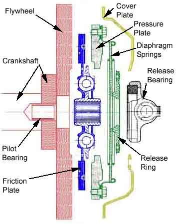
A typical 4-cylinder clutch kit: (Image: Leyland Workshop Manual)
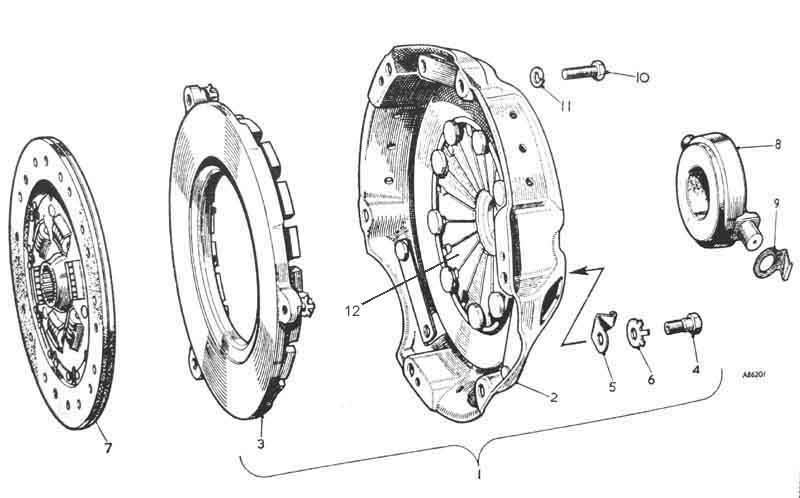
Consisting of:
'3' the pressure plate
'4', '5' and '6' attach the pressure plate to the cover plate
'8' the release bearing
'9' the spring clips that fasten the release bearing pivots to the release arm (not shown)
'10' and '11' fasten the cover plate to the flywheel (not shown).
'12' are the diaphragm spring fingers that press the pressure plate against the friction plate a flywheel to transmit rotation from the crankshaft to the gearbox first-motion shaft.
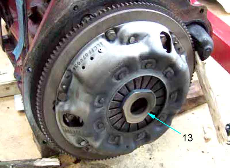
By contrast the V8 (and Midget 1500) clutch does not have this release ring as they use a roller-bearing release bearing, and the face of that rotates with the cover plate so does not need the smoother surface the release ring provides.
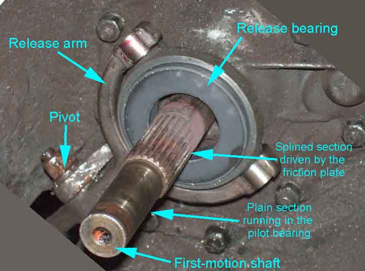
The 4-cylinder graphite release bearing with the gearbox first motion shaft protruding, showing the splined section that engages with the splines in the friction plate and the plain section that runs in the pilot bearing in the crankshaft. The release bearing is attached to the release arm and can move towards and away from the flywheel, but does not rotate. Note that with the clutch pedal released the first-motion shaft is rotating with the pilot bearing and crankshaft, but with the pedal depressed the first-motion shaft rotates independently of the crankshaft, and the plain section of the shaft is running in the pilot bearing.
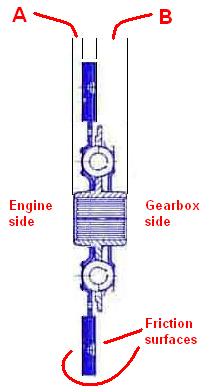
Which way round does the friction plate go? It's often not marked, but there are two ways to tell. The first is that the splined boss sticks out much further on one side (B) than the other (A), and this side faces the gearbox:
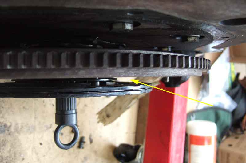
The second way is to offer it up on the alignment tool, and if it is the wrong way round there will be a large gap between the friction surface and the flywheel:
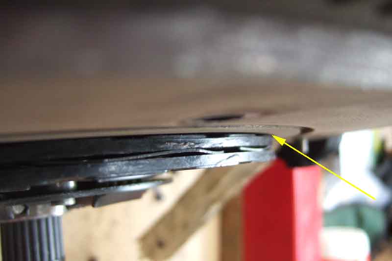
Fitted the correct way round there is no gap:
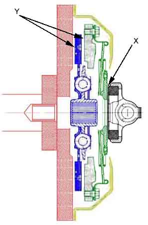
A simplified and exploded view of the component parts. The gearbox first-motion shaft passes freely through the release bearing, cover plate and pressure plate. The splined section is engaged with the splines in the friction plate, and the plain section is inserted in the pilot bearing in the crankshaft.
Clutch engaged: With the cover plate bolted up to the flywheel diaphragm springs push the pressure plate against friction plate which slides on the splines of the gearbox first-motion shaft and is pushed against the flywheel (pressure at points 'Y'). All three rotate as a unit, and drive is transmitted from the engine to the gearbox. The plain section of the shaft is rotating together with the pilot bearing. A clearance is shown at point 'X' simply to show the release bearing is not pushing against the release ring at this time. However in practice this will not be the case as a spring inside the clutch slave cylinder will be gently pushing all the release components together to take up any free play.
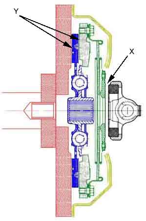
Clutch disengaged: Now the release bearing is pushing the release ring towards the flywheel (pressure at point 'X') which moves the inner ends of the diaphragm spring fingers towards the flywheel, hence the outer ends of the fingers away from the flywheel, which pulls the pressure plate away from the friction plate. This allows the friction plate to move away from the flywheel (clearance at points 'Y'), so the flywheel, pressure plate and cover plate can now rotate independently of the friction plate and hence the gearbox first-motion shaft. The plain end of the shaft is now rotating independently of the pilot bearing.