
About a year ago a friend bought a 'barn find' (actually garaged for four years) 78 GT for a song which only took pump points cleaning and clutch bleeding to get going, even passed its MOT. However the clutch seemed to be slipping a bit although only in 4th and had a high biting-point, so that was obviously on the way out. 12 months on it is much worse, slipping in all gears now, and I was game for the challenge. Bought a B&B clutch kit, checking that the release bearing was of the bonded type and not the pinned type.
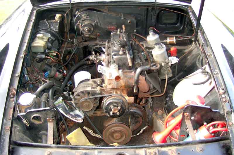
Dismantling was straight-forward enough - until it came to the nuts holding the rubber mounts to the chassis rails! I left the carbs and alternator on the engine but removed the air-cleaners and put paper bungs in the cab throats. I removed the distributor which enabled me to remove the starter from above (although possibly only the top bolt into the bell-housing needs to be removed, the bottom bolt could be left in and the motor left attached to the engine). Note these two bolts have different threads, one coarse as it screws into alloy and the other fine as it screws into steel. Whilst removing the solenoid operate connector the spade broke off the solenoid - repair number one. And when removing the servo hose (which needed replacing) I had to cut through its servo hose clamp as it had seized solid. The oil-cooler pipes were a pain - why is it that it is the adapter that always comes loose from the block first and not the pipe union? It means you have to get another big spanner or something (I wedged a screwdriver between the flats and the back-plate for the rear pipe) to undo the pipe union. Taped up the block fitting to stop debris falling in. Wrap some paper round the oil filter and head to stop oil dripping out, and prop the ends of the hoses up high for the same reason. I left the oil-cooler in-situ (and hence that end of the pipes) as it was underslung like a V8, also the diaphragm, but removed the radiator. This isn't strictly necessary with a late model with the forward-mounted radiator as there is more than enough room to get the engine forward to clear the first-motion shaft, and if you are worried about hitting it you can put a board in front of it. But it had been fitted on the wrong side of the diaphragm and I wanted to correct that, and in the event I would have had to remove it anyway as will become clear. Only one of the studs on the exhaust manifold sheared, but I had bought a full set as a precaution. Decided to pull the rack as it was going to be hard enough to get at the engine mounting bolt that side anyway. Easy-peasy with the track-rod end taper cracking scissors, although the clamp bolt in the UJ and the rack shaft needed a bit of persuasion.
But those mounting nuts! They fought us every inch of the way, despite releasing fluid, WD40, undoing them a bit then working them back and fore and so on. Space is very restricted, you can only turn them half a flat at a time. Fortunately I had a slim ring-spanner that I could get on, an open-ended would never have done it. They were so tight I was having to bash the other end of the spanner with a lump hammer to get them to move at all, which lying on my back under the car and working above me was extremely hard work. Keith (the owner) could only be there occasionally due to work commitments, but fortunately one of his free periods coincided with this so he was able to help by pulling on a rope running under the car (forwards for the one side, rearwards for the other) tied to the free end of the spanner while I lay underneath moving the spanner half a flat at a time. We got the first one off but the 2nd was even harder! It was so stiff after a while the rubber part of the mount was twisting, which meant the nut didn't undo so much, sprung back when he released the rope, and I couldn't get the spanner on the next half-flat. Eventually I drilled a small hole through the edge of the bottom metal plate of the mount and the chassis bracket with the intention of putting a pin in the hole to stop the mount twisting, but in the event the drill snapped as it broke through and did the job anyway. After that it was relatively straight-forward (but still a lot of pulling on the rope) to get the nut the rest of the way off. I did loosen the two front nuts and bolts that hold the mount bracket to the engine front plate, but there is another bolt underneath that and there is no way of getting to that until you remove the mount from the bracket, which I didn't think I could do with the engine in the car (unlike the V8). The only other way I could see of releasing the engine was to lift the engine to 'stretch' the mounts, then cut through the rubber or chisel it of the plates to release the engine, then grind the bottom plate of the mount off the chassis brackets. Fortunately we didn't have to go that far, as it would have meant another trip to Leacy for new mounts (but see below). Just to get that far took half a day, and as it was getting on for tea-time we decided to leave it there, with the engine ready to do a 'Playtex' i.e. lift and separate next day.
Next morning I was on my own again. Assembled the hoist, wheeled it up to the front of the car, only to find that even with the arm at it's fullest extent it didn't even reach the front of the engine! I didn't think removing the front bumper would have given me enough movement even though the rubber bumpers are pretty thick, so I had to push the hoist in from the side, and even then it only just reached over the rocker cover with about an inch to spare (thick cloths over the wing to prevent damage from the pump which was also in the way!). Slung a tow-rope through the eye in the hoist, down between the alternator and the block behind the front mount brackets and in front of the sump, up and through the eye again, then down the back of the engine and under the back behind the sump, and tie off. Started jacking up and tested the 'twang' of the front and rear parts of the rope - it's important to lift the engine so that it will be as square as possible to the bell-housing as they are parted to avoid damage to the first-motion shaft, and it seemed fine. Before jacking up any more I removed the top two bell-housing bolts while I still had the space, there was another one a bit lower down on the left, but a space below that where it seemed like there should have been another, and another space on the right below the starter. These were undone using a combination ring/open-ended spanner, the ring is at a slight angle, and I fitted it to the bolts the 'wrong' way round so the arm of the spanner was angled forwards instead of backwards. That left just the two bottom bolts which I had checked were free but retightened, so that as I jacked the engine up to clear the mounts from the chassis rails it lifted the gearbox with it and they remained together, the bottom bolts holding the bottom of the joint together, and the forces pressing the top of the joint together even though the bolts were out. You need to jack it until the bell-housing reaches the tunnel, or nearly so, which is why the top bolts are best undone first. Once up far enough a trolley jack under the forward part of the bell-housing jacked up a little bit more just so as it is taking the weight of the gearbox, then you can undo the bottom bolts. A bit of a pull and the joint parted, staying nice and square so confirming the engine was correctly balanced.
Now came another tricky bit - because the hoist was in from the side, and the front wheels at least only go back and fore and don't pivot, I couldn't easily pull the engine clear of the first motion shaft. I had to tie a rope to the engine and pull it back (i.e. towards the front of the car) as far as I could, tie it off on to the bonnet slam-panel (hence removal of the radiator required anyway), then get under the car and drag the wheels of the hoist sideways a bit, then pull on the rope a bit more, drag the wheels a bit more and so-on until the clutch cover-plate was free of the first motion shaft, then I could jack the engine the rest of the way up to clear the top of the wing, and pull it backwards away from the side of the car. Once clear of the car I lowered it onto a saw-bench for some stability but still left the hoist taking most of the weight. Phew! Not bad going, but still took a couple of hours to get that far.
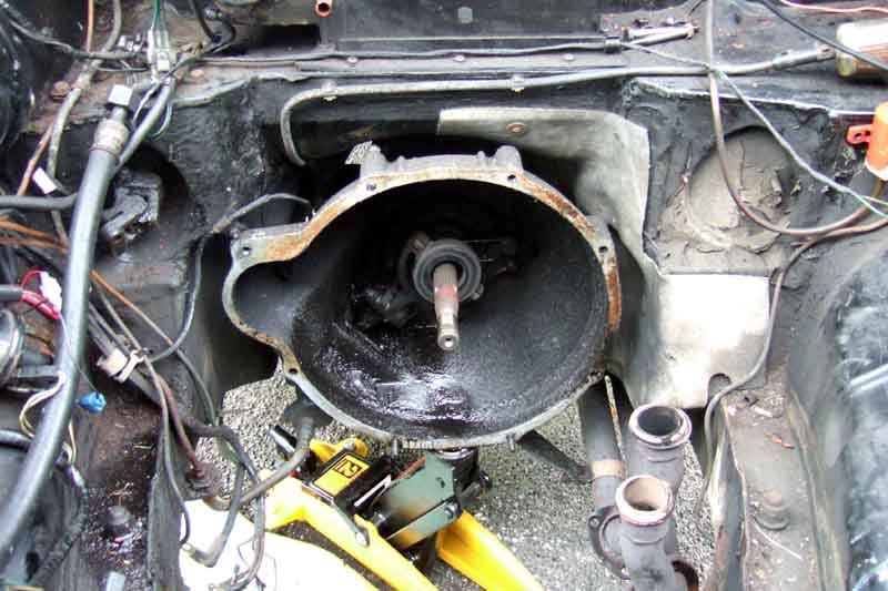
Gunky oil in the bell-housing, around the release arm rather than straight down from the first-motion shaft and cleaner oil if it had been the oil seal. I would very strongly advise freeing-up the connection between the clutch hydraulic pipe and the end of the hose, and the locknut securing the hose to the bracket on the chassis rail while the engine is out even if you don't think you will be removing it later. It's an absolute pig when the engine is in.
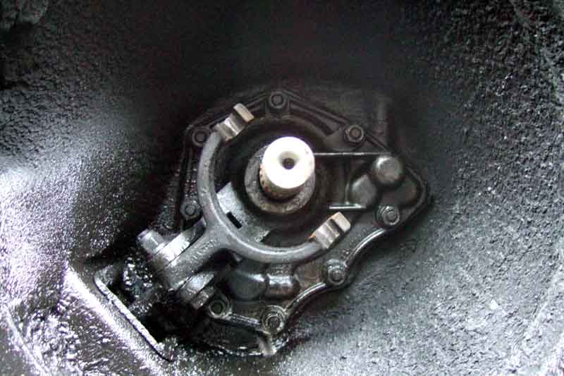
No visible seepage from the seal itself, so just checked the nuts on the seal plate for tightness. Check the release arm does not wobble on its pivot, but still moves freely. If the arm wobbles the release bearing can be off-set to the cover plate which causes premature failure. Also note that the release arm fork is pretty-well concentric with the first motion shaft, which wasn't the case on Bee in July 2016.
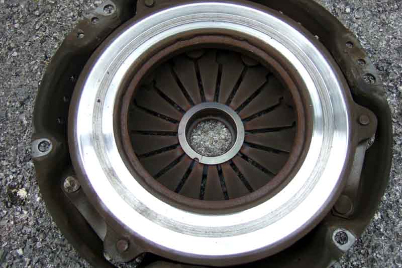
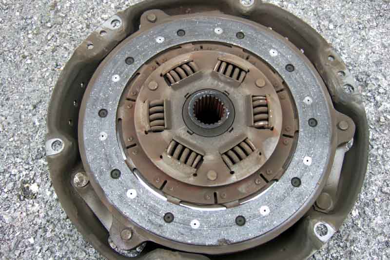
Undid the cover-plate bolts, but it stayed where it was, the diaphragm spring pressure should have pushed it off at least part of the way, but I had to lever it off the dowels. It wasn't jammed, it was just that it was so badly worn there was virtually no spring pressure left on the friction plate! The cover plate was badly scored, the friction plate being down to the rivets that side, but fortunately not quite as worn the other side although the raised pads had vanished from that side as well. No blueing or cracking from excessive heat from slipping, a very slight but even wear mark the full width of the flywheel, and even though at first sight there did seem to be a ring where the rivets had been it was only a polish mark and not a groove. Some good news, at least.
Friction-plate down to the rivets, fortunately only on the cover-plate side (facing upwards here).
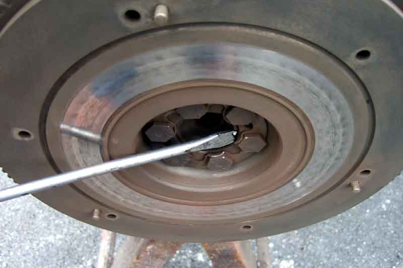
Flywheel fortunately sound. Only a very slight depression across the full width, what looks like a groove from rivets is actually only a polish mark as can be seen by the reflection of the screwdriver. No blueing from the slipping or sign of oil from the crank seal.
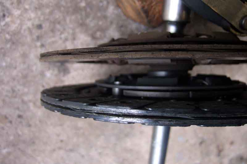
Old and new friction plates - the old has the pads completely worn away both sides plus about half the base material on the cover-plate side. Quite a difference in thickness between old and new, together with the wear on the cover plate it's not surprising it was slipping and the springs wouldn't push the cover-plate off the dowels. Note the centre section containing the damper springs and splined boss projects much further from the face of the friction surface on one side than the other, uppermost on both these. This side faces the cover plate, if incorrectly fitted it prevents the friction surface from reaching the flywheel. So offer up the new one first to double-check, and triple check any 'flywheel side' legend on the new friction plate.
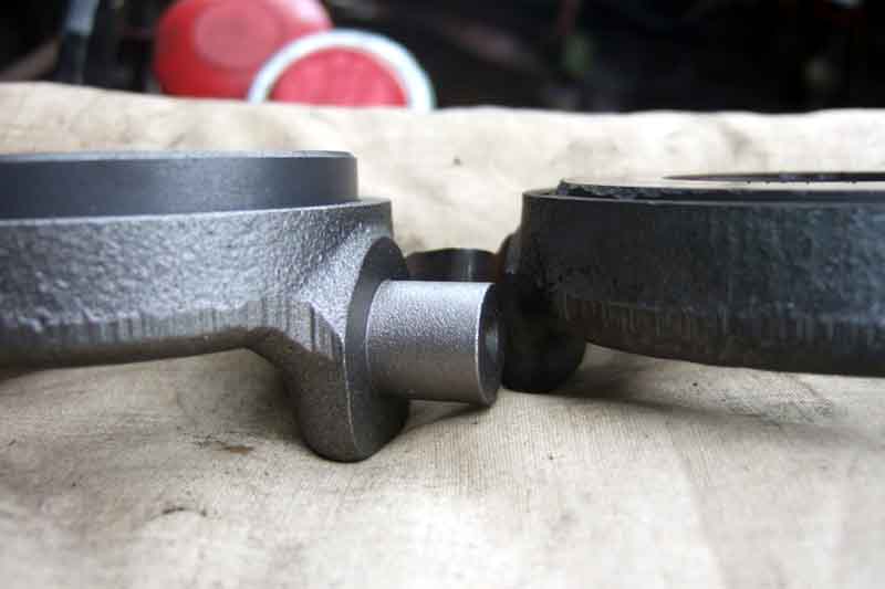
New (left) and old (right) release bearings - plenty of meat left on the old, perhaps only 1/3rd worn, as in theory the boss on the cover plate can go right down inside the release bearing casting. However the release bearing would need to be exactly concentric with the cover-plate boss, and in practice it seems there can be significant misalignment between the two which would mean that as soon as the graphite has worn flush with the bearing casting, you get metal on metal and very rapid wear on both, to be followed by catastrophic failure of the bearing casting. Under those circumstances, this bearing is just about worn out.
A useful set of instructions with the clutch describing things to check (like same size etc. as the old parts), clean (like the greasy film off the rubbing surface of the cover plate), and most importantly that the new friction plate fits over the splines on the first-motion shaft! Cleaned all the old friction material dust off the flywheel, slotted the friction plate onto location tool, and the plate and tool to the flywheel. Offered up the new cover plate and fitted the bolts, this time there was probably about 1/4" gap left to the flywheel when the bolts started taking up spring pressure. Mindful of people having fitted the friction plate the wrong way round (the flywheel side should be marked as such) I took the cover-plate off again and doubled checked. But note that the central section on the friction plate containing the damper springs and splined boss projects much further from the friction material surface on one side than the other, this side faces the cover plate. Fit the friction plate with your alignment tool to the crankshaft and check it is reaching the flywheel before fitting the cover plate. If you get it the wrong way round the damper springs will be resting on the flywheel instead of the friction surface, and the cover plate will be much further away when you start to tighten the bolts. I wasn't able to fully torque them up (25-30 ft lb) as I needed to stop the flywheel turning and decided it would be easier to wait until Keith came by again than rig up something myself (rope fed through a plug hole to stop the piston reaching TDC is one method I have read of). Unhooked the spring clips holding the release-bearing to the fork, carbon still visible above the edge of casting so still plenty of life left, but certainly not worth leaving. There was quite a bit of really thick black grease/oil at the bottom of the bell-housing, but with the bearing off I could see there wasn't a leak from the oil-seal, so just checked the bolts on the plate the seal sits in for tightness. The clutch kit includes a little tube of grease so smear some on the pins of the release bearing and fit that to the fork and refit the springs.
Time to get the carbs and exhaust manifold off to drill and retap for a new stud. Used a small drill first to check it was in the centre of the old stud at both ends - a little bit of side drilling required to square it up, then through with the correct size, taper tap, plug tap, screw in stud with double nuts and job done. When I came to refit it with a new gasket I found the same thing had happened as to the tubular V8 manifolds in that it had warped, and the outer holes on the manifold were closer together than the holes in the head. I fitted one, then tapped a screwdriver down between the centre branch and its adjacent stud to spring that a little bit, then between the outer branch and its stud to spring that as well, and got the other outer bolt in. Smears of Hermetite red on one face of each joint for the intake (there are no less than eight joints!) and bolt them up. The HIF are convenient in that the link pipe that feeds fuel from the front carb to the rear helps to keep them together and all the linkages in place. Cleaned up the studs on the mounts as best I could and worked a nut up and down each one with copper grease until they turned relatively easily.
Keith arrived again, just in time to hold the flywheel while I finished torquing up the cover-plate bolts. More clutch grease on the nose and splines of the first-motion shaft and the splines of the friction plate, then hoist the engine to clear the wing, push it over the engine compartment following the tracks made in the drive when pulling it out, and lowered it to be in line with the first-motion shaft. Tied off the engine again while we kicked the legs of the hoist sideways, then gradually released the rope and fiddled with the height to line it up. One very useful tip is just before the end of the shaft enters the hole in the cover plate feel with a finger to check the clearance is the same all round, and when you start moving the engine onto the shaft check the teeth on the flywheel are square with the bell-housing when viewed diagonally downwards from each side. Get the same alignment of flywheel to bell-housing all the way round and the engine has to be square to it as well as at the correct height and sideways alignment. I don't know whether we were particularly lucky, but just turning the crank pulley nut while pushing the engine forward, then giving it another push, and it went right on! I did see a recommendation that if you jack one rear wheel, put it in gear, you can use the rear wheel to turn the first-motion shaft into alignment. Personally I think it is easier to turn the crank pulley - put it in gear as before but this time make sure the rear wheels aren't going to turn i.e. lock the first-motion shaft in place, while you turn the crankshaft into alignment. We didn't put it in gear i.e. the shaft was free to turn, maybe we were just lucky, or maybe the grease on the nose and splines of the shaft helped. Bolted up the bottom of the bell-housing, lowered the jack, and lowered the hoist to get the mounting studs into the slots. This was a bit tricky as they were about 1/2" too far back. I probably should have disconnected or slackened the engine restraint tube on these models, but with a bit of pulling and levering we got them in. Fitted the locating plates, washers and nuts under the chassis mounting brackets - another fiddle as you can only get a couple of fingers up from below and one in from the side, and they did up a lot easier than they undid. Then it was a matter of refitting things that needed two pairs of hands while Keith was still around like the exhaust (new sealing rings, metal side down as that was how they came off), I had to disconnect the front restraint strap as it was holding the exhaust in the wrong place. The rack needed a bit of persuasion again to get the splines inserted, check the notch in the shaft is aligned correctly with the split in the UJ i.e. there are the same number of splines each side. We chocked the back of the UJ against the firewall while tapping the rack casing with a hammer and block of wood, and it went in easier than it came out. With the starter I tried soldering another spade to the stub of the broken one but the rest of it broke away as well, what it is made of goodness knows. Fortunately the ends of the solenoid wire were sticking up a bit so I was able to wrap a short piece of wire round that with a male spade soldered to the end. Refitted the starter with me underneath supporting it while Keith got the top bolt in, then the bottom. End of day 2.
Then it was a matter of fitting oil cooler and gauge pipes, wiring and plugs to starter and alternator, carb throttle and choke cables and fuel pipe, heater tap control cable, and hoses. Both the bottom hose clips would only tighten up so far 'before jumping a tooth', as it were, no spares to hand, so they would need replacement. Cut the new servo hose to length and fitted that, with a spare clip that I did happen to have to hand to replace the broken one. Refitted the distributor, removed No.1 plug and turned the engine with my thumb over the hole to find TDC of the compression stroke, and see where the rotor was pointing. It was in the correct place (about 2 o'clock) so on went the cap and leads. Reconnected the battery and tried cranking, OK so the starter repair is good for the time being at least. Tried starting it and it was trying to go, but wouldn't catch. Wandered round to the front of the engine to ponder why and I noticed I had left the paper bungs in the throat carbs! Removed those and it fired up nicely, ran it for just a few seconds as I hadn't put any water in yet because of the hose clips.
Nothing for it now but to bite the bullet and test the clutch! So light it obviously wasn't doing anything, but as I was on my own I couldn't operate it and look at the slave push-rod at the same time. I'd had the slave off at one time while I removed the starter, and even though I put it back once the engine was out the spring inside the master would have pushed the piston out quite a way moving the release arm with it. Couldn't see why it would need bleeding as I hadn't opened the hydraulics, but nothing else to be done. Tried from the top down first of all using a Gunson's EeziBleed on the master - no change. Next I tried reverse bleeding with the Gunsons connected to the slave (having first removed some fluid from the master to prevent overflow) - again no go. Then I tried removing the slave and reverse bleeding it while hanging off the hose i.e. air at the highest point by the hose connection but again no-go. Then I tried manually pushing and releasing the piston. Lots of gurgling from the master so I thought 'Ah-ha' but it did it every time I pushed the piston back, so I guessed it must be sucking in air past the seals as the spring pushed the piston back out rather than drawing it down from the master. Then the slave started dripping fluid, so that was it another trip to Leacy's and more of Keith's money spent, also got a new flex hose. On my return I couldn't shift either the nut holding the pipe on the chassis end of the old flex hose, nor shift the hose or its locking nut on the chassis bracket. Keith said to leave it and we would deal with it when we had to. The problem is that the hose ports were tapped differently old to new (and yes I did move the bleed nipple from its shipping place to the correct place) so when the hose was tightened the only way the slave would sit on the bell-housing was by twisting the flex hose. Fortunately by fiddling about with various copper washers I was able to line it up. Tried reverse bleeding with a pipe connected between it's nipple and the right-hand caliper nipple while Keith pumped but there still didn't seem to be any pressure on the pedal. Next took the slave off the bell-housing and tried again this time with it hanging on the pipe. This time when I pushed the piston back I could feel the pressure from the fluid as I forced it back into the master, but again once attached Keith said he still couldn't feel any back-pressure. However when he pumped it I could see the push-rod moving, but only by about 3/8" and not the 1/2" or so I have seen before. So I tried, and it was indeed very light, but I thought I could feel some back pressure. Nothing for it to start the engine and tentatively try selecting reverse - and it went in as quiet as a mouse! Not only that the biting point was where I would expect it, so it seemed to be working properly (thank goodness!), just very light!
After that it was just a matter of finishing off the hoses, fill with water, retime, and take it for a test drive - perfect, very light and as smooth as silk. The top hose seemed to be dripping by the thermostat housing, so we removed it, spotted what looked like a pin-hole just on the hose side of the clip, so cut that bit off and refitted as there is room to do that with that hose. One of the heater hoses was also leaking at the heater even though the clip was tight (I'd put some Waxoyl on the worm 'threads' which usually helps old clips but not in this case), I had a new clip that size so replaced it and solved that. 15 minutes to replace the clutch, 2 1/2 days dismantling and reassembly!