
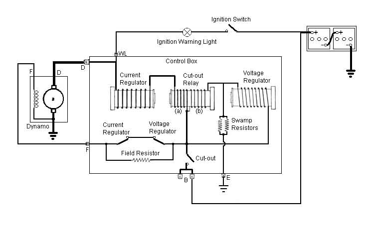
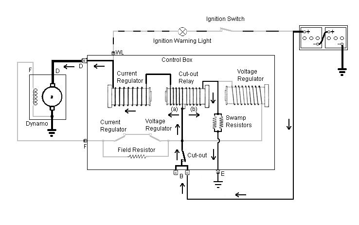
A schematic of the control box and what is connected to it, hopefully a bit clearer than the 'physical' layout in the Workshop Manual.
But to simplify things further I've broken it down step-by-step into what happens at each stage of its operation.
First the ignition is turned on, and current flows from the battery, through the ignition switch, the ignition warning light, a link inside the control-box, and through the low-resistance armature winding of the dynamo so lighting the warning light.
Next, the engine is started, the dynamo starts to turn, generating a small voltage from its residual magnetism. This is fed back into the control box, through the low-resistance current regulator and cut-out relay (a) windings, the voltage and current regulator contacts which are both still closed at this stage, and to the dynamo field winding. This boosts the dynamo output and the additive effect causes a rapid rise in dynamo output. Whilst the dynamo voltage is rising towards battery voltage some current still flows through the warning light, but it will be dimming. At the same time dynamo output is passing through the high-resistance (b) winding of the cut-out relay and the swamp-resistors to earth.
Eventually (although the engine revs will probably have to increase above the normal idling speed) the voltage rises sufficiently to operate the cut-out relay (12.7 to 13.3v). Its contact closes, and starts to feed dynamo output to the battery and the rest of the cars electrics. The voltage on the 'D' terminal is now almost the same as the battery voltage, the only difference being the very small voltage dropped across the two low resistance windings of the current regulator and the cut-out relay. As the voltage on the 'WL' terminal is always the same as on the 'D' terminal, the warning light now has virtually the same voltage (i.e. above the 12.7v to 13.3v of the cut-out relay) on both sides, so the light is extinguished. If anything causes the dynamo output voltage to differ (higher or lower) from the battery voltage by more than a few volts, the light will start to glow again - the bigger the voltage difference the brighter the light.
The dynamo is now charging the battery, and raising its voltage, and the voltage regulator is sensing that voltage. Eventually the voltage reaches the required level, the voltage regulator relay operates, it's contact opens, which connects a resistance in series with the field winding, which reduces its current, and hence dynamo output. Not having a resistance i.e. if the contacts just broke the circuit would have a very similar effect, but would generate significant arcing which would rapidly burn the contacts. The resistor greatly reduces the arcing, without adversely affecting the voltage and current control.

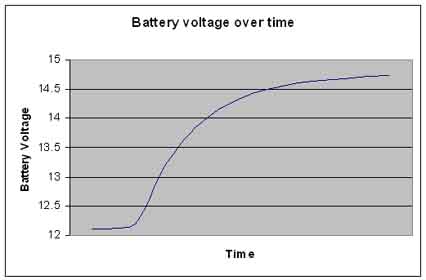
In practice, and under most circumstances, the voltage regulator relay doesn't just operate and remain operated, but is operating and releasing all the time - when it operates it reduces dynamo output which causes the regulator relay to release which generates full output again, which operates the regulator relay again, and so on. When the battery needs charging the voltage regulator contacts are closed for a relatively long time and open for a relatively short time, which gives a relatively high average charging current. As the battery approaches fully charged the situation gradually reverses to one where the contacts are closed for a relatively short time and open for a relatively long time, giving a relatively lower average charging current.
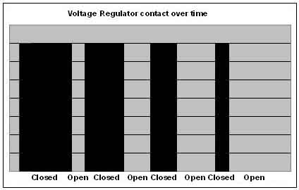
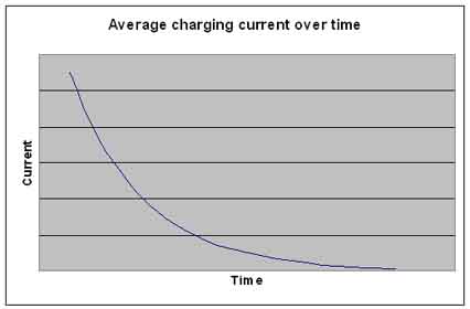
This opening and closing is a very rapid process, and can be felt as a vibration if you lightly touch the voltage regulator armature, and there is a small arcing visible at the contact. The effect of this is to give a rapid initial rise in battery voltage, tailing off as the battery reaches fully charged (ranging from 14.9 to 15.5v at 10C to 14.3 to 14.9v at 40C).
A similar situation occurs with the current regulator. As the current from the dynamo reaches its maximum safe value the current regulator relay operates, its contact opens, which also inserts the field resistor in series with the dynamo field to reduce the output current to a safe value (19 to 22 amps). This also reduces dynamo voltage, and if this drops below battery voltage then the battery will supplying part of the cars electrics, and hence discharging to some extent. Whilst both current and voltage regulator circuits could be operating at the same time it's more likely that the voltage regulator relay will be released until demand on the dynamo reduces and the current regulator relay releases.

Now lets consider what happens when the engine slows and reduces dynamo output. Before that happens the dynamo output is flowing through the current regulator windings, and both low-resistance (a) and high-resistance (b) windings of the cut-out relay in the direction indicated, and charging the battery. The two windings of the cut-out relay are such that when current flows through them both in this direction the magnetism to operate the relay is additive.
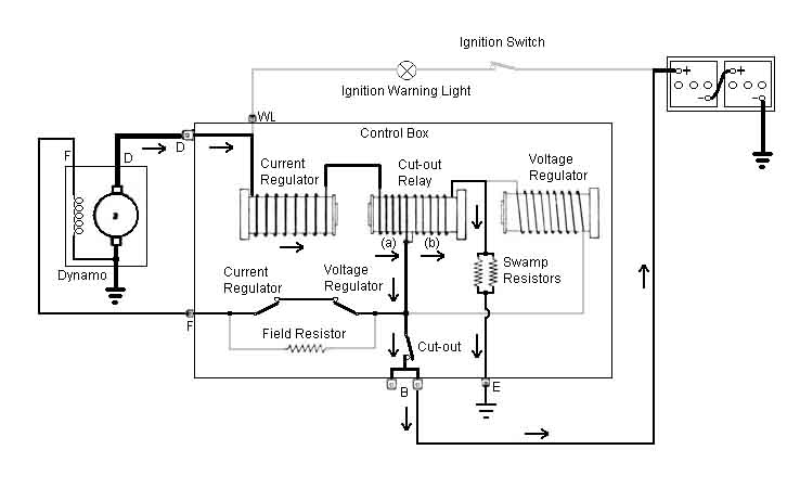
As dynamo output reduces to below battery voltage, current will start to flow the other way through part of the circuit i.e. from the battery, in the reverse direction through the cut-out relay low-resistance (a) winding and the current relay, and through the dynamo trying to 'motor' it i.e. the dynamo will be consuming battery current rather than charging it. Because the dynamo output is now below battery output there is a potential difference between the D and WL terminals and the battery, and the warning lights starts to flicker and glow, a common situation at idle. Battery current is also flowing through the high-resistance (b) winding of the voltage regulator in the same direction as before, but because the current through the low-resistance (a) winding has reversed the magnetism of these two windings is now in opposition. As the magnetism created by (a) increases it eventually becomes equal and opposite to the magnetism created by (b). When this happens the cut-out relay releases, and disconnects the battery from the dynamo. This happens when the reverse current is between 3 and 5 amps and the system voltage has dropped to between 9.5v and 11v. The warning light is now glowing at full brilliance. Without this current reversal i.e. if the cut-out relay were simply sensing dynamo voltage, it would never release, even when the engine stopped as it is also sensing battery voltage, and the high current from the battery through the control box and the dynamo would destroy them very quickly. This is why you should never manually operate the cut-out relay with a stopped engine, as the relay will 'latch in', and unless you force it to release pretty quickly damage will occur.
Finally let's consider what happens when you switch off the ignition of a running engine, say one running fast enough to keep the ignition warning light off i.e. the dynamo is charging the battery. You should notice that immediately you turn off the ignition the warning light comes on fully, and the engine starts to die. When you first turn the ignition off, you have disconnected battery voltage from the switch side of the warning light, but it still has full charging voltage from the dynamo side. However also on the ignition switch side of the warning light are the feeds from the ignition switch to the ignition coil, fuel pump, instruments etc. This allows current to flow from the dynamo, through the warning light and those components to their earths. This current is more than enough to light the bulb, but not enough to keep the ignition system producing sparks, which is why the engine dies.
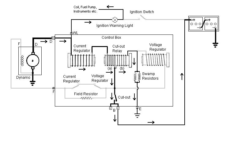
As the engine dies the dynamo output voltage drops, but initially the warning light remains bright as current can flow from the battery via the low resistance windings of the relays to the WL terminal. As before the reducing dynamo voltage causes the cut-out relay to release, the warning light is now solely dependant on dynamo voltage, and flickers and dims to nothing as that slows to a stop.
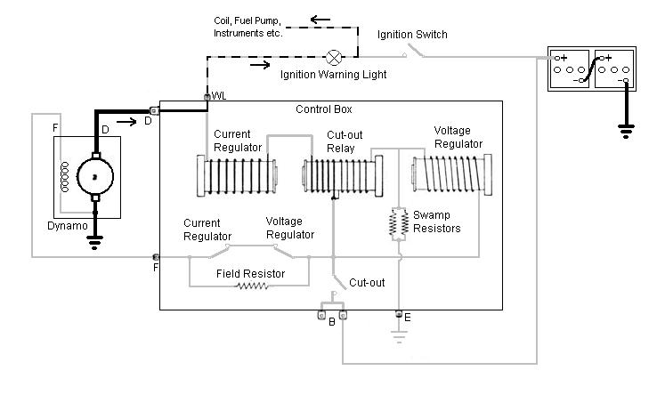
So, what are 'swamp resistors'? It took me quite a while to find out and I only did so as a result of a question from Jouko Kuisma in Finland in September 2020, which set me off on another Google search, and I found this Lucas Generator Output Control document. On pages 28 and 37 it describes how the swamp resistor is a relatively high value special alloy resistor that has a low temperature coefficient i.e. it's value varies little with heat. It is in series with low resistance coil windings that do vary in resistance with heat, but as both are in series the overall current varies relatively little, compared to earlier versions that had higher resistance coil windings and no resistor. So basically the stability of the resistor 'swamps' the instability of the windings. This is in addition to bi-metal strips on the regulator relays which vary their operate and release characteristics to compensate for changes with varying heat. There are two resistors in parallel to share the current load, if there were only one it would need to be half the value to maintain the voltage characteristics, would carry twice the current and have twice the heating effect, and so need to be physically bigger or have a heat-sink to dissipate that heat without damage. Having two smaller ones wired in parallel, but physically separate, is an alternative method of dissipating the heat over a larger area.