
Tank to Pump Pipe - CB and RB, pump to carbs, and body harness, and boot/loadspace:
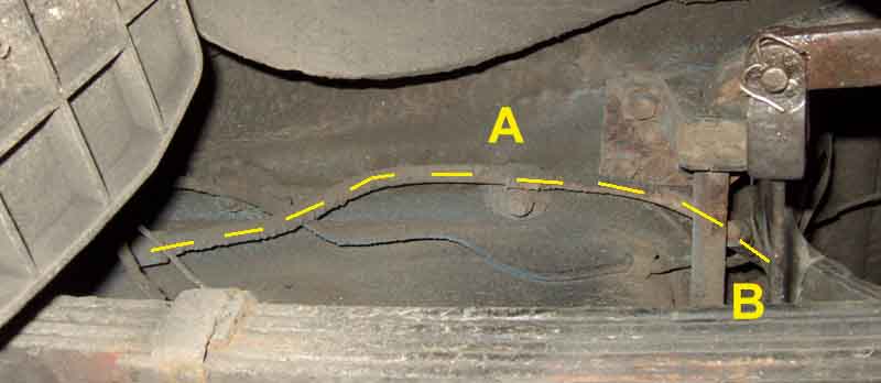
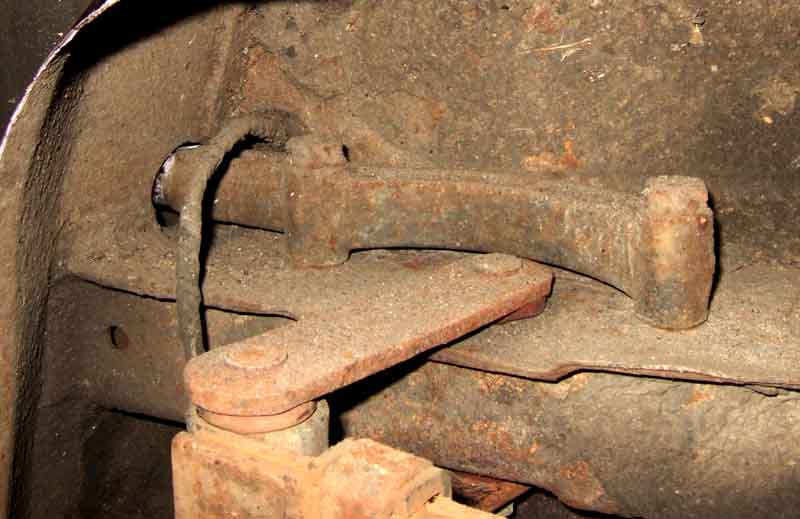
CB: Alongside the tank, round the axle strap towards the middle of the car:
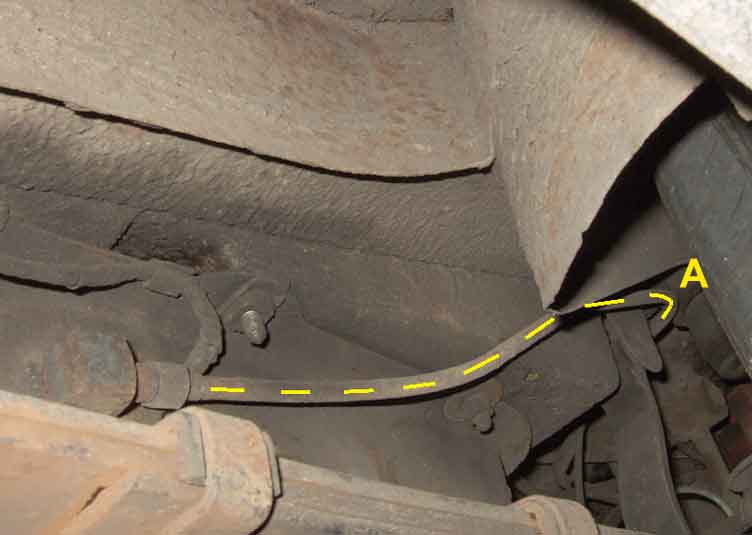
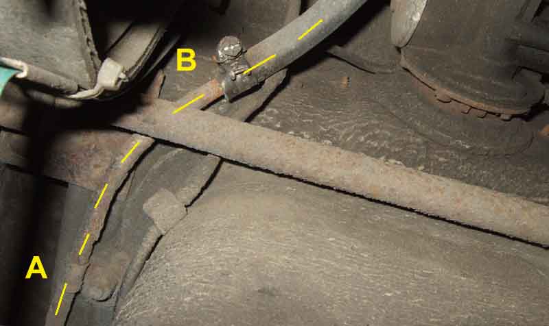
Then turns over the axle:
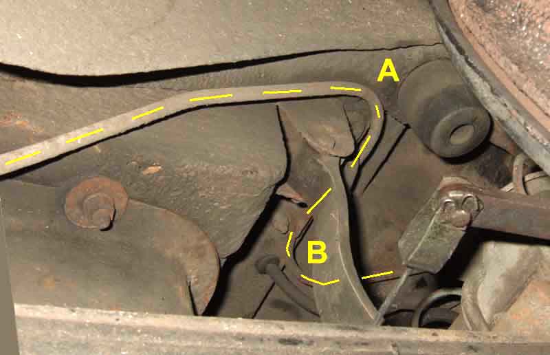
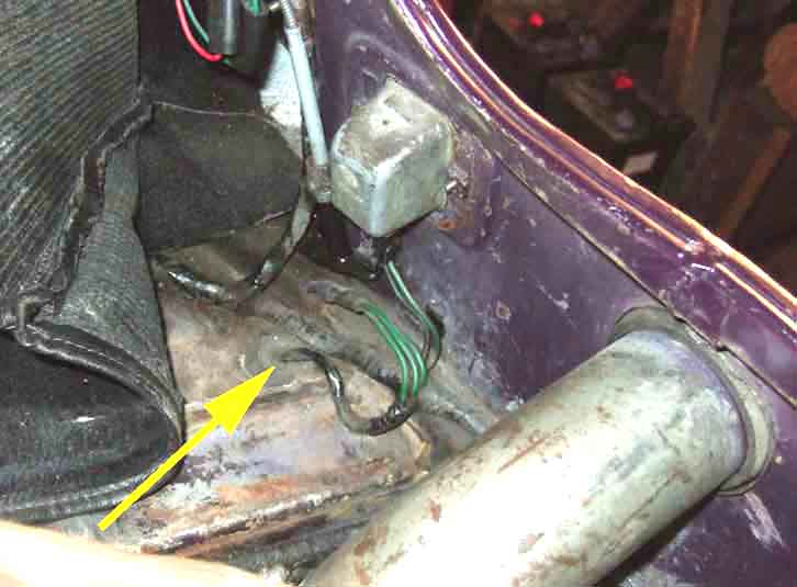
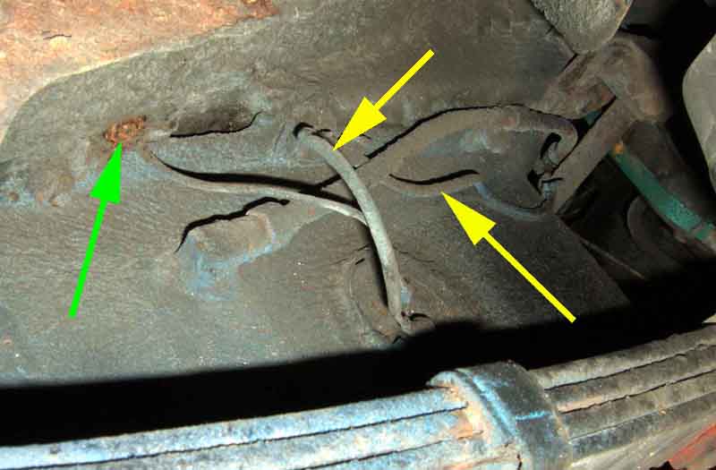
Picking up the harness and a pump breather tubes:
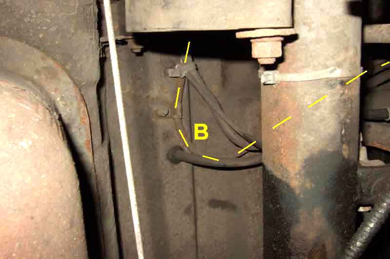
Alongside the battery box:
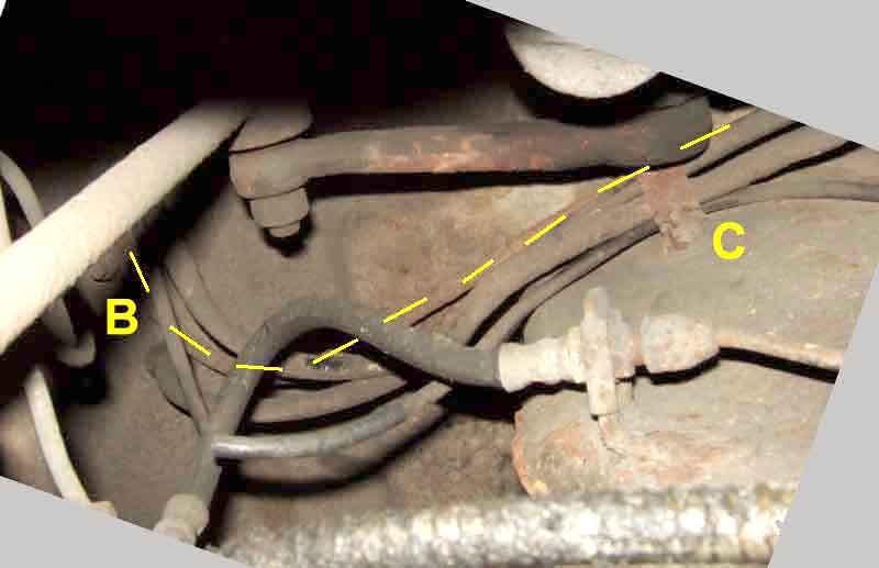
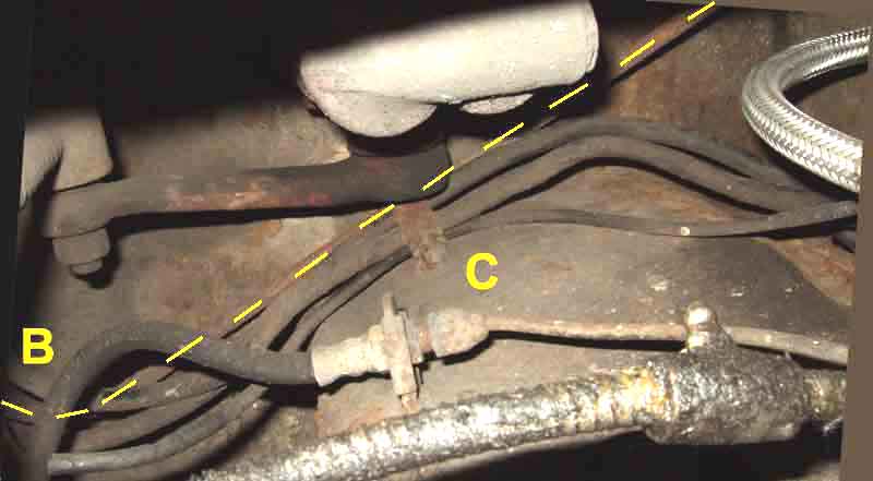
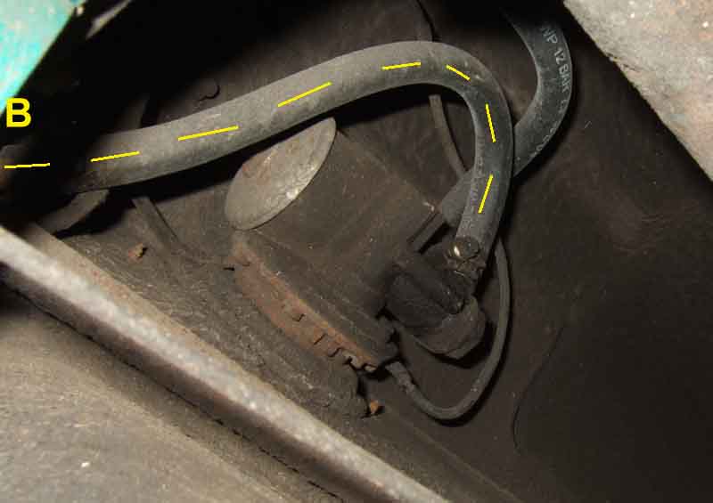
To the pump (note braided hose replaced with plain):
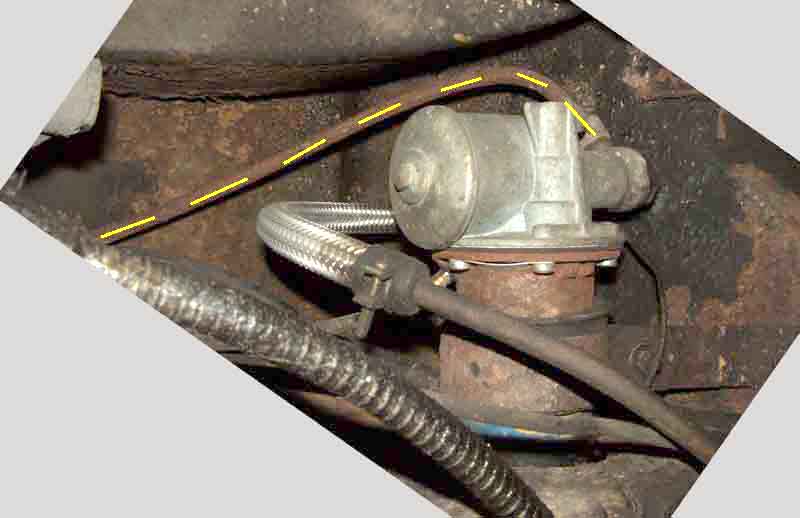
Going back to a hose
To the pump:
Pump to carbs - the rear two small and larger comb:
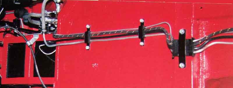
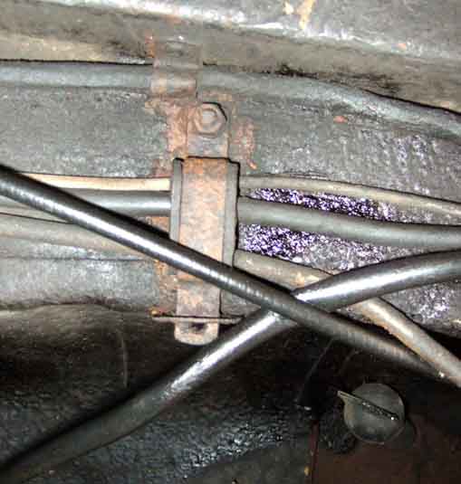
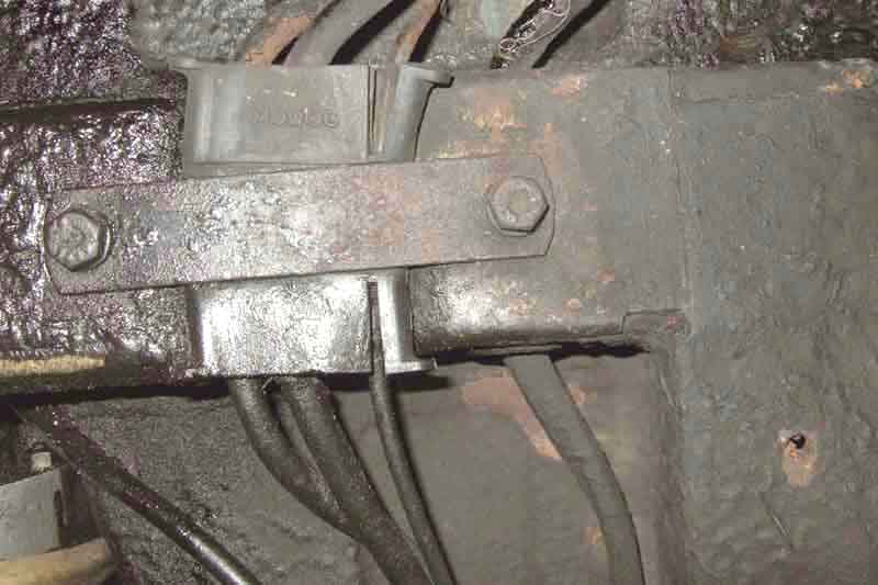
The small comb in front of the gearbox crossmember on Mk1 cars ...
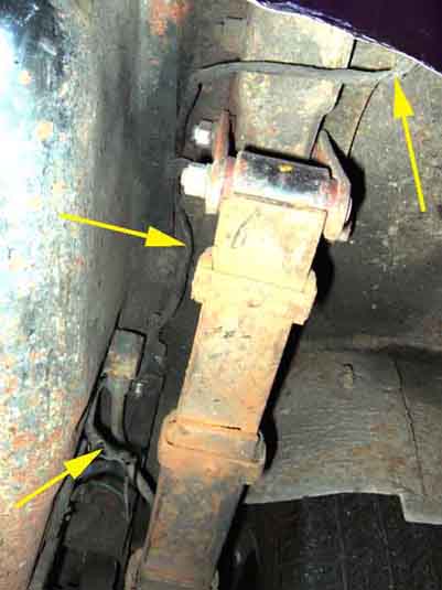
... and on Mk2 cars with the wider tunnel. The end of the strap fits through a slot in a tab welded to the side of the tunnel. This also shows how the rear harness is routed alongside the other three with P-clips instead of going through the same small combs, this one and the next one back being riveted to the side of the chassis rail:
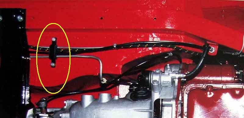
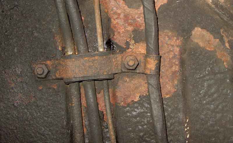
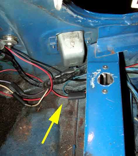
The rear harness now passes through two grommets in the fixed crossmember instead of a channel and comb with the other services:
And through P-clips attached to the outboard comb retainer in the other two positions aft of the fixed cross-member:
Boot/loadspace:
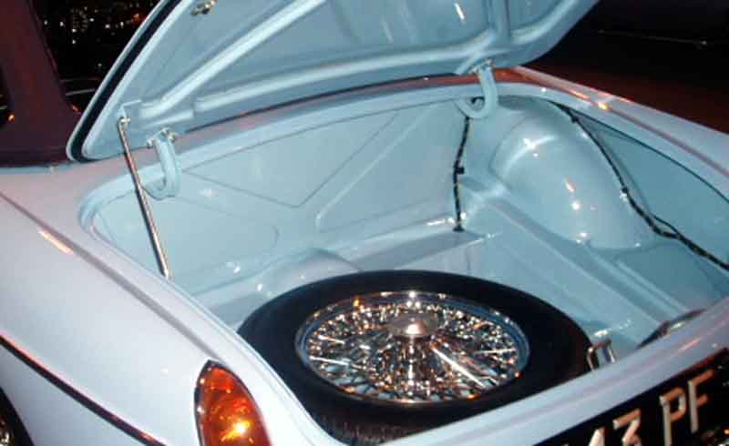
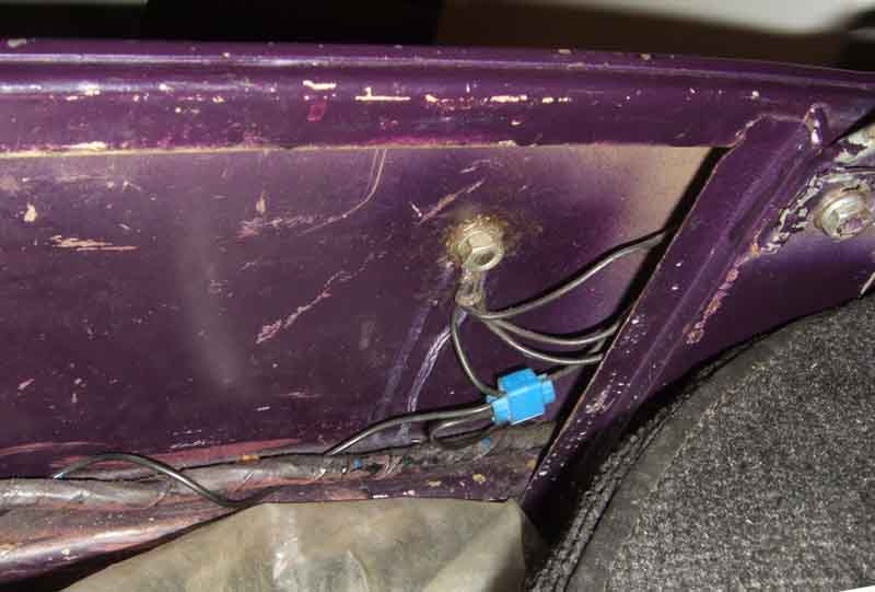
On roadsters the harness enters the boot on the 'shelf' and goes up the rear bulkhead (two spot-welded tabs with plastic sleeves) and over the arch (two more tabs), then along the join between the outer wing and the boot side floor to under the off-side light cluster (one P-clip on the lower inboard stud). Then along the join between the rear panel and the boot floor (two more tabs) to the near-side light (and another P-clip on the lower inboard stud: (MGste)
On GTs the harness travels back along the floor (clipped), to the offside light cluster, then as for the roadster: (Clausager)
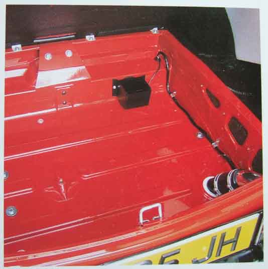
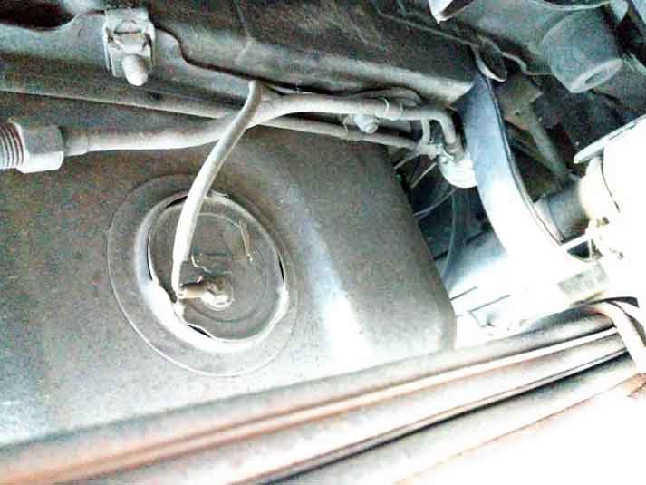
On CB cars the tail to the fuel tank sender stays in the harness until the back of the boot floor, then goes out through a hole by the off-side light cluster:
Under the bumper iron and chassis rail:
And forwards to sender, clipped to the edge of the tank:
RB cars still have the hole at the back of the boot but with a plastic plug:
The 1976 (4-cylinder) of a pal in America - the same single wire coming from the harness but with the earth spade on the sender unused, which means mine is probably a PO bodge, maybe from a replacement tank having been treated 'too well': (Bill Etter)
Earthing points:
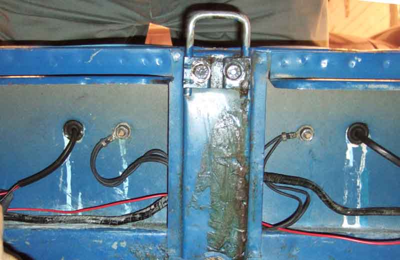
75 V8, five earth wires at two points - two reversing lights, two number-plate lights and the pump. Although a sixth is shown for the fuel tank sender on both CB and pre-77 RB diagrams it does not exist here, and there is a local earth provided near the sender:
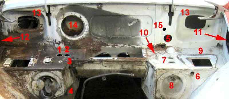
Bulkhead holes and grommets:
1, 2 and 3 are for the temperature gauge capillary (where used), 4-cylinder heater valve cable or V8 choke cable with grommets RFR503, and 4-cylinder oil pressure gauge pipe with grommet AAA643 (was ACH805). I'm not aware of a definitive statement of what goes where, there are several arrangements pictured in Clausager. The oil gauge grommet is an odd pointed one, and I have one like that in the side hole on my roadster, with two flat ones in the shelf. One picture does show the oil gauge pipe coming from the side hole with a tortuous path up, back and round to attach to the hose connector, even though there is a logical path up one of the shelf holes and straight into the connector, which another picture does show. The heater valve cable almost certainly does use one of the shelf holes, and the temp gauge capillary could use the other one of those or the side hole. There are pictures showing the temp gauge capillary coming through 1 with a support clip under the oil hose connector and the heater cable coming up 2, which does leave the oil gauge pipe in 3. Temp gauge capillaries should normally be supplied with a grommet already fitted, or you have to cut one through from the edge and slide it on.
4 is the speedo cable (ACB8474, was RFR405) on all RHD, and earlier LHD, although I have a picture of an LHD with the cable entering at 3, and seen one of the cable entering at 4 only to come out at 3 and go across to 15.
5 is for the screen washer tubing, the choke cable on 'top-down' HIF carbs, and V8 heater cable. Not grommeted originally as it is in a double-skin section of the bulkhead, and there is the large open hole for the bonnet hinge immediately above it. Grommets for anything passing through this hole need to be on the cabin side in the footwell for sealing purposes, probably RFN303. However if they rattle about in this hole then a grommet will prevent that.
6 is for the CB choke cable - both HS and early bottom-up HIFs - and needs a grommet as this section is single-skin, RFN303.
7 is two small elongated grommets (AHH6478) to block up the holes for the LHD steering column bolts on RHD cars, on the other side in LHD cars.
Similarly 8 is the plastic blanking plug for the LHD steering column on RHD cars ...
... and 9 is the blanking plate and gasket for the LHD pedal box on RHD cars.
10 is a small plastic plug on RHD cars, grommeted for the accelerator cable on LHD.
11 is the bonnet release cable in the cavity, but secured in the panel with a nut so no grommet is used.
12 is the main wiring harness which should have its own grommet already fitted. The link below lists this as 3H1547, but my two grommets have a much smaller sleeved hole which is a snug fit to the harness, and a flat membrane between that and the grooved section that fits in the body aperture. The V8 oil pressure capillary also goes through here using its own grommeted hole above the harness grommet. In theory it could go across the engine compartment to the holes on the shelf and down one of those, the length would be the same, but there are only two holes there already occupied by the temp gauge capillary and the choke cable, the V8 does not have the third hole on the side.
13 are the large bulkhead grommets behind the master cylinders (14B630, both sides).
14 is the heater inlet seal 17H3714 which is attached to the heater casing.
15 is the speedo cable entry point for later LHD cars, possibly May 72 on.
Also on the heater itself are matrix port seals 7H1993, and strip seals AHH6290 between the heater casing and the bulkhead shelf, not forgetting the dread rubber block BHH389 between the heater and the bulkhead.
The following pages contain information on the plugs and grommets used on the MGB:
Edge-clip info supplied by MGSte (Images from Brown & Gammons):
BHA4473 secures the harness to the edge of the bonnet slam panel.
Moss Europe
Rimmers
MGOC
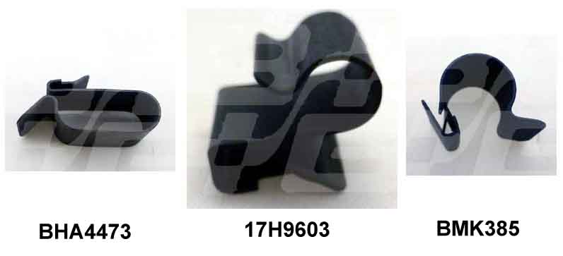
17H9603 (3/16) secures the brake pipes.
BMK385 (1/4) secures the fuel pipe.