


Remove/Refit
Combustion chambers
Valves
Rockers
Rocker Cover
Head Gasket Leak
Valve Leak and Unleaded Conversion
V8 Cylinder Heads
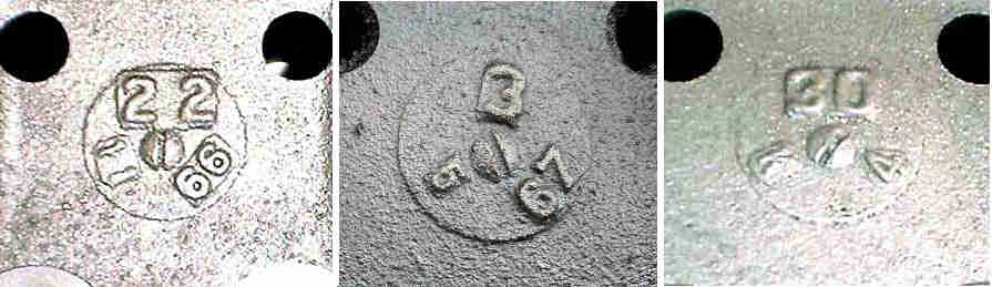 Cylinder heads can be dated from a casting number and (usually) a date code cast into the upper surface, so easily seen by removing the rocker cover. See also this information from Sean Brown's Flowspeed page.
 At least two changes in design, possibly 1970 and 1972, the earlier ones seem more prone to pinking.
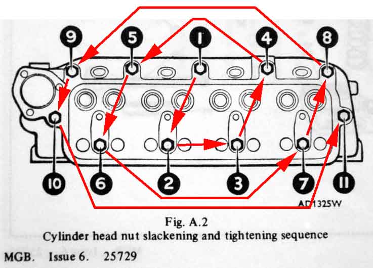 It's very important to get the cylinder head nut sequence right both for slackening and tightening if head warp is to be avoided. Looking at the drawing the order might seem random, but in fact it starts in the middle and spirals out anti-clockwise from there, finishing on the rear-most bolt. I hadn't realised the 'spiral' feature until I came across a drawing on a commercial site showing it, although whether I would rely on working that out as I go along instead of leaving the socket on the most recently slackened/tightened nut before looking at the drawing to see which is next is another matter.
Equally important is how each nut is slackened and tightened. You must not go for everything in one go i.e. slackening the first nut right off before moving onto the second, neither must you apply full torque to the first nut before applying any torque to the second, and so on. They must all be slackened and tightened progressively no more than one turn at a time each between starting to undo and moving free of the head or rocker pedestal in the case of slackening, or starting to apply force to the head or rocker pedestal and reaching the final torque in the case of tightening. It's also very important to be aware that the manifold-side nuts and studs on each rocker pedestal also clamp the head, so you cannot remove the rocker pedestals without going through the full cylinder head slackening and tightening sequence, which means draining the coolant.
When slackening I'd advise doing it until they just start to come clear of the head. You may find that valve spring pressure pushes one end or other of the head up anyway, alternatively with them all fully loosened the head could be stuck fast. If the latter then with the spark plugs still in ... and power to the fuel pump disconnected or the carb feed hose blocked off if using the ignition key - crank the engine and compression pressure will hopefully loosen the head. If not you will have to resort to careful malleting and levering. With the head loosened it's probably best to remove the rocker shaft now - if nothing else it removes quite a bit of weight when you are leaning across to the middle of the car and trying to wiggle the head up off the studs. Lift it up carefully, making sure each push-rod comes free from its rocker. If stiction pulls a push-rod up, that can pull the cam-follower up, and it can drop off and lie tilted across the hole it should be sitting in, which will probably mean you will have to remove the engine side-covers to reseat it. Once the rocker shaft is off lift each push-rod in turn slightly - you will almost certainly feel the weight of the follower, so twiddle the push-rod and waggle it from side to side until the follower drops free and the lower end of the push-rod can flap from side to side. As you lift each out in turn have a piece of card to hand with numbered holes for the push-rods, to ensure they go back in the same place. After that it's a case of grasping the head as best you can and wiggling it off the studs. If you have had head gasket failure then check for surface damage and flatness and examine carefully for any cracks - this Flowspeed page gives several examples.
When refitting a head the threads must be oiled and the nuts running freely or the torque figures will be reached before the correct clamping force is exerted. Also you need to be careful how many times you reuse the head studs. How many of us know if our engine has been apart, let alone how many times? I reused mine the first time I had the head off for a leaking exhaust valve as I tried undoing a couple with double-nuts and got nowhere. It's said that if running the nut down the stud encounters a tight spot then that implies the stud has stretched so should be replaced. But you would have to test that without the head in place as the stretch could have occurred anywhere down to block level - or even below it, so I wouldn't rely on that. And in any case typical MGB studs have a threaded section at either end and a plain section in the middle so you can't run the nut all the way down anyway. The second time I really didn't want to reuse them again, which meant the studs had to come out come what may. After much pondering and investigating shock forces on the end of a stud before trying to undoing it, with and without heat, and limited space for Stilson's, I decided to splash-out £21 on a Laser impact stud remover with my air gun and they all came out relatively easily. The next quandary is what to replace them with! There have been several reports that standard studs from the usual suspects are very poor quality with them snapping before they have got up to torque the first time. So far better to spend the money on a set of ARP, and for road use they are said to be good for the life of the average owner! Clean and dry the block face before reassembly.
Before fitting new studs I've seen it said that you should check the flatness of the block and if there is any raised area round the stud holes then it should be removed or it can prevent the head clamping the gasket correctly. Others say if the block shows that then it is scrap. The holes in the head have a clearance round the studs, and there is the thickness of the gasket to take into account, so if any raised portion IS holding the head up then the block is definitely scrap! When fitting the studs make sure the block holes are clear of any water or pooled oil as that can stop the studs going down as far as they should, which will reduce the number of threads engaged, and can hydraulically fracture (fracking!) the block. I checked the depth of the holes against the length of the threads and all were well over, and the lightly oiled studs went in with only light pressure for the whole length of the thread. If they don't then you should clean the block threads, although a full-blown tap may not be a good idea in case it takes metal away, use a bolt with a couple of hacksaw cuts along the length of the thread. DO NOT torque the studs into the block. Some say it will crack the block, but that will only happen if the stud is going to bottom of the hole, which with the partial threading that these studs should have can't happen, but you could still damage the threads at the top of the block making subsequent removal and replacement difficult.
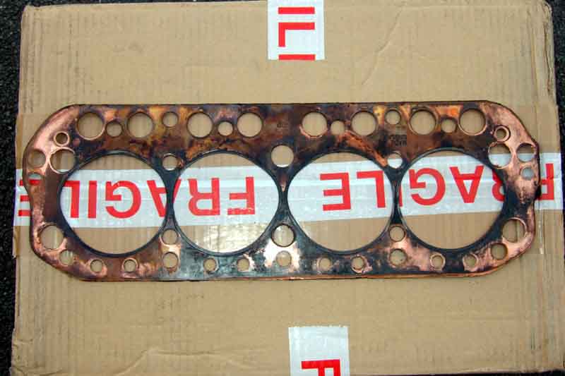
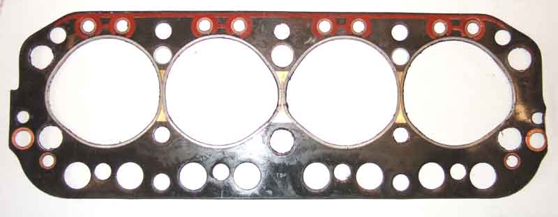 Fit a new gasket - noting the TOP and FRONT marks. You can't get the long edges on the wrong sides as there are five studs in a row on the manifold side and only four on the plug side, but you can get it upside down. The original copper gaskets are quite easy as the copper side faces up and the 'steel' side down, and the TOP and FRONT marks are very clear. But the Payen gaskets are not so clear - not only are the sides very similar in appearance but the TOP and FRONT marks are small and not very distinct. A clearer indication is on the front and rear edges - the front edge has a distinct step but the rear edge is only a curve (same with the copper). However on the block both edges are stepped, and on the head both are curved, so why that particular feature exists I can't imagine!
Clean and dry the head face, and when picking up the head avoid wrapping your fingers round under the head onto the gasket surface. This is not so much to avoid you trapping your fingers between head and gasket as to prevent getting dirt and grease between the head and the gasket! It's easier to fit the head minus rocker shaft - not only for its reduced weight when leaning across to the middle of the car and trying to get all the studs in the holes in the underside of the head without damaging the face, but you can only get the push-rods back in with the head on. Drop the rocker shaft and pedestals onto their studs, and now you have to get all the push-rods into the recesses in their rockers. If you tighten the smaller pedestal nuts first that will lift the head off the gasket where valves are open, and the push-rods for closed valves will flop about. Fit the eleven larger head nuts first, and as you tighten them make sure the push-rods are seating as you go. Closed valves will have their push-rods down and won't seat into the rockers until the head nuts have pulled the head down almost all the way against open valve spring pressure. Alternatively you can slacken the adjusters right off - after-all they are going to need readjustment anyway. With all the head nuts tightened down you can fit the smaller pedestal-only stud nuts. After fully tightening, and refitting all the ancillaries, and maybe leaving overnight for things to settle and re-torque next day, set the valve clearances. At this point I started the engine with no coolant - for just long enough to make sure everything was working OK. If you don't get it too hot - or when cool enough, refill the cooling system with plain water and run to check for leaks. Then drain as much water as needed to get the required volume of neat anti-freeze (assuming you don't bother with any of the fancy dilute alternatives) back in. The carbs having been off you should probably check the air-flow and mixture balance.
To re-torque or not to re-torque, that is the question ... Next day after first fitting the head then set the valve clearances before any running, and again after about 500 miles with copper/sandwich gaskets (some recommend periodic re-torquing with these). Re-torquing after running should not be done with Payen gaskets (see this SC Parts page) because of the sealant coating these gaskets have that is activated by heat. It isn't necessary with the steel shim gasket on the V8 (use Wellseal as a sealant), and only initial torquing should be done on modern engines where after reaching the final torque figure the nuts are tightened a further number of degrees. Each nut has to be slackened slightly to break thread stiction before being tightened again with a torque wrench. If you start to slacken the nut with a ring-spanner you will almost certainly see the free end of the stud turning with the nut to begin with before it moves independently. This is normal and is just the elasticity of the stud plus the effect of thread stiction. Once the nut moves relative to the stud it is ready to re-torque back to the correct figure. If you use a socket to slacken you won't be able to see the stud, a quarter-turn of slackening should be enough. Work round them in the standard tightening sequence, DO NOT do what I've seen suggested and undo each nut completely, and slacken and re-torque each nut in turn i.e. do not slacken them all then re-torque them all.
After many years a pal said his was hissing as well, so he was going to get a new rad cap, and I started thinking about it again. A pressure test showed the 10lb cap was only holding a few psi, and soon lost that after switch-off. So that explains why it was sucking air back in as it cools, but why was it constantly pushing air out? Nevertheless I bought a new rad cap, which now held 10psi, but was still pressurising up to that and hissing - sometimes. Again I put it to one side.
Then in May 2014 just before a run I noticed the temp gauge oscillating wildly just as the stat opened, and it lost a bit of coolant. "Stat sticking", I thought, so changed it. Despite testing the new stat was OK before fitting it there was no change. As this was very similar to the problem I'd had with the V8 some years ago which could well have been the pump, and I'd been carrying a spare pump round with me for 17 years, I decided to change the pump - but no different.
 By this time I had put a pressure gauge on the cooling system utilising a Tee in the hose between the heater valve and the heater. What that showed was brisk acceleration causing a rise in pressure, that did not drop back! More gentle driving showed a similar rise in pressure, but slower.
Finally I did a combustion leak test of the air in the rad, which I probably should have done sooner if not years ago, and there is CO there so the head gasket is leaking. First decision is what type to fit? Originally copper, but first Americans started talking about Payen, now discussed here as well. Suppliers seem to have one or the other, so no point in asking which one they recommend. One acquaintance with connections talked about the usual problems of quality, small scale production, and competition on price rather than quality which didn't fill me with confidence for either. But Chris Betson of Octarine Services sells and fits Payen, and presumably if there were any problems with them he'd be getting cars coming back, so I think on balance that gives me more confidence.
I've also done a compression test for the first time in very many years - never had reason to before now. 1, 3 and 4 were 160 to 173psi dry, 173 to 185psi wet. No 2 was 127psi dry and 138psi wet so significantly low. The dry to wet increase is pretty-much the same for all cylinders, so bores look OK, but I need to check the valves to see if that's the cause of 2 being low, or whether it is something else. I also did a sort-of leak-down test. I don't have the pukka kit so I just connected my compressor tyre inflater to an old spark plug with the centre drilled out, and a tyre valve soldered in. When in cylinder 2, with all the plugs out, I could hear hissing in cylinder 3. Consulting the valve sequence, No.3 exhaust valve is open with No.2 on TDC on the compression stroke, so the diagnosis was No.2 exhaust valve leaking.
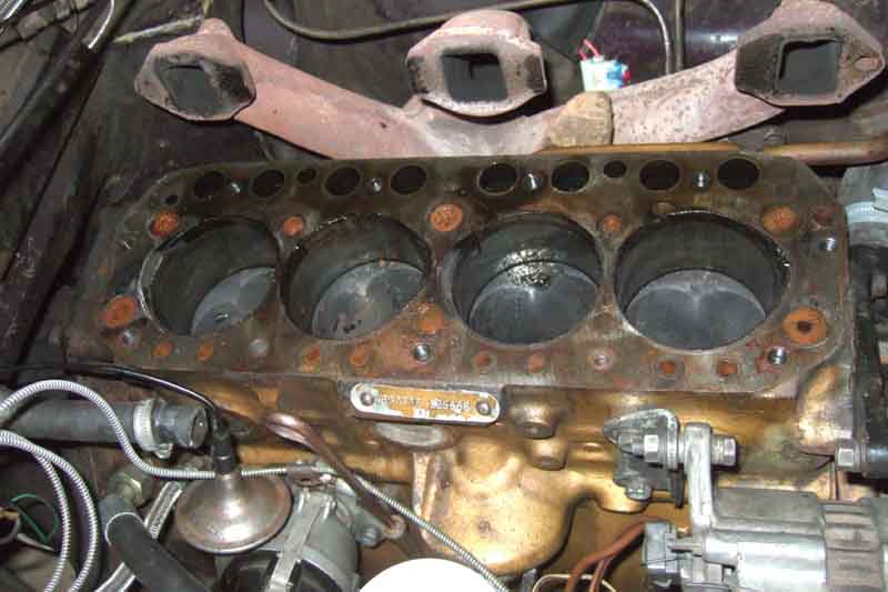
 Dismantling completely uneventful (however see the 'Gotcha!' that stopped Herb Adler lifting the head, also his further head gasket and cam follower problems). Draining the coolant first, as before I removed the bottom hose from the rad, but this time with a large padded envelope acting as a shoot and positioned such that virtually every drop went into the bucket. I disconnected the strap between the exhaust down-pipe and the bell-housing, and that was enough to pull the manifold off the studs and tie it to the bonnet prop. No horrors anywhere, although it looks like combustion gases have been seeping past the gasket towards the water passages for sometime, maybe a torque-down would have cured that, but the leaking exhaust valve on No.2 still needed attention. One interesting thing is that the block is stamped '+.040' i.e. 40 thou overbore, almost certainly part of the Gold Seal rebuilding. I removed the head complete with rocker shaft as the cam and push-rods are helpful in breaking the gasket seal, but it lifted right up. Carefully broke the stiction on the push-rods so they wouldn't lift the cam followers out of their sockets, which if they fell to one side would need removal of the tappet chest covers to rectify. I was taken aback by how heavy the head was - reaching across to the middle of the engine while trying to lift it off all the studs. Previous experience of heads has been on the V8 which are alloy hence lighter and angled towards the sides of the car hence a shorter reach. I wasn't sure if I would be able to lift the head back on, holding it up while trying to locate the studs in the holes.
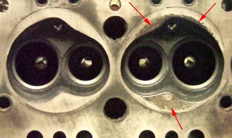 I said 'no horrors' but what was intriguing is that the flat parts of the head that are part of the combustion chamber were quite pitted on cylinders 1 and 2, and 2 even showed some erosion of the edges. By contrast 3 and 4 were perfectly clean and flat. I do run Bee on the verge of light pinking, although when faced with steeper hills on some runs she does tend to pink more. Maybe it's the effects of that and for whatever reason 1 and 2 are more prone than 3 and 4.
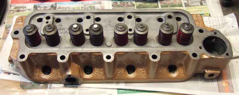
 Waiting for the replacement head gasket kit (Payen) gave me time to clean everything up and investigate the valves. Nos.1 and 2 exhaust valves are white, but not 3 and 4, indicting the front carb was weaker than the rear carb, which could also contribute to pinking on those two cylinders. A little petrol poured into each combustion chamber shows 2 is leaking very slightly, as suspected. I remove all the valves to check the seats and lap them in, no obvious damage on No.2 exhaust, and quite easy to get a nice grey seat all the way round the valves. When removing them on No.1 the spring compressor pushed the spring retainer down easily to allow me to remove the collets, but most of the others were well stuck. When under tension from the spring compressor the spring retainer needed a sharp rap with a hammer to free them from the collets. An hour or so with coarse and fine grinding paste left them all with a nice, even, matt grey surface. Another test with petrol showed No.2 exhaust was fine, but a couple of the others had the tiniest weep. So removed the valves again, wiped the valve and seat sealing surfaces, replaced the valves, and gave them a twiddle with the lapping tool to fully seat them before refitting the spring retainers and collets. This time all were sealing perfectly.
 I removed the thermostat housing and the new thermostat, to drill a 2mm hole in the outer part of the thermostat, to overcome the problem of this type of stat with no bleed hole trapping a vast amount of air under it until it gets hot enough to open - not good as it also means most of the engine has no coolant in it.
 Bee has always been oily round the rocker cover, even though I have tried gluing the cork gasket into the cover, and using gasket seal onto the head. So some time was spent in cleaning the effects of that up from the rocker cover, head, carbs and such-like. I became aware some time ago that the cover had obviously been overtightened in the past, as the nuts were bottoming, and the sides had bulged out slightly. However the base where the gasket goes was flat and level, and even adding more packing under the fixing nut cups didn't keep it oil free. But when examining the cover closely I realised the holes in the top where the rubber seals fit, were bowed instead of flat. So the rubber seal rocked in them, and it was only sealing in the fore and aft position, and not at the sides - so that was where the oil had probably been coming from all these years, but wasn't visible until it had run down as far as the head. Pondered a while how to deal with that, and came up with squeezing the cover in a vice, with appropriately-sized sockets on both sides of the holes. First attempt at just clamping them up still left them slightly bowed, so I clamped them up again and rocked the cover top and bottom and side to side, which wiggled the holes nice and flat.
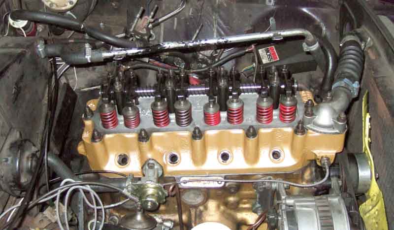
When the gasket kit arrived it included valve stem oil seals, which weren't on originally, so I left them out. Very carefully cleaned and smoothed the head and block surfaces. I tried to remove the studs but they seem stuck fast. Given the effort in lifting the head off, I pondered some kind of support along the engine bay I could rest my arms on while locating the head over the studs. I tried a couple of lengths of timber but nothing really suited, in the end I decided to lean my elbows on the heater casing and the rad diaphragm, and without the additional weight of the rocker shaft this time it wasn't too difficult. Torqued up the head bolts carefully (45-50 ft lb), refitted the push-rods and rocker shaft, torquing that up as well (25 ft lb). November 2016: I wrote the preceding sentences, but they puzzle me. One of each of the rocker shaft pedestal bolts is also a head bolt, and there is no way you can torque up the head properly without the rocker pedestals - at least - fitted. I certainly didn't strip the rocker shaft, so must have torqued up the head with it fitted, even if I lifted the head on before fitting the shaft assembly. Checked the torque several times over the next couple of hours, and twice I could add a little bit more, presumably as the gasket crushes into place.
The exhaust manifold lifted straight back on, but the carbs were a bit of a fiddle keeping both interconnecting shafts correctly located while lifting the carbs back onto the manifold studs, which needed a couple of goes, plus reattaching the cables. The carbs probably took half the time of the reassembly so far. Manifold nuts are torqued to 15-16 ft lb. I left the down-pipe to bell-housing strap disconnected for the time being.
I then had to leave it for a few days as I was away walking in the Lake District, and on my return adjusted the valve clearances. These have always been a bit of a pain, as some valves have their greatest clearance one side or the other of the strict 'rule of nine' point. The easiest way to adjust the valves is with the car on a flat and level surface. Put it in 4th, and with the plugs out you should be able to nudge the car forwards (and back) by pushing on the top of a front wheel. When you run out of space knock it out of gear, roll the car back to the starting point, put in back in 4th gear, and carry on.
Because I wanted to recheck the head bolt torque after a few hundred miles I didn't want to stick the rocker cover gasket down. The pressed steel cover is more convenient than the alloy, as it has retainers at each end and each side that hold the gasket in position while you fit it. From what I hear the alloy just has a flat base hence has to be glued to keep it in position, as between two flat surfaces (the head is flat) it would squirm out when tightened. Having corrected the bow of the holes in the top I was careful to torque these down as well - just 4 ft lb. Refitted the heater return pipe from heater to bottom hose.
Refitted the modified thermostat and cover with yet another new gasket, a smear of sealant on both sides, torquing down to 8 ft lb.
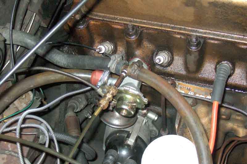
I'd removed the heater tap from the head before removing the head, so this went back on, with a smear of gasket sealant on both sides of the new gasket, remembering to put the support bracket for the temp gauge capillary on the lower stud.
Refitted the top hose - despite this being 'bellows' shaped it has to be slid onto the rad port as far as it can go before it can be fitted to the thermostat outlet, then slid back so that there is about an equal amount of each port covered.
Refilled with the coolant saved from draining, and with the hole in the thermostat it took the whole amount. I spun the engine on the starter with the plugs out until I had oil pressure, then peered through the oil filler cap looking for oil around the rocker shaft. It takes a surprisingly long time for oil to get here, but appeared first in the cups of the push-rods, then from under the rockers on the shaft. Replaced the plugs and the plug leads.
Nothing for it now but to fire it up! Started straight off, and immediately peered over, under and round looking for problems like oil or water leaks. None found, so drove it out of the garage, turned it round and drove partially back in so that the exhaust was pointing out of the garage but any oil would land on the garage floor and not the drive! Warmed it up, and with the hole in the thermostat it was noticeable that the header tank on the rad started getting slightly warm - not surprising as now there is a small passage for coolant to flow all the time. Temp gauge rose steadily until about mid-way between C and N where it stopped - lower than before. Pressure gauge reading about 5 psi. I spent the next few minutes balancing the carbs for air-flow. Lifting them just off idle the rear carb was pulling very slightly less air, so I slackened the clamps - and spent the next half hour trying to get it back to as close as it was before! Checked the mixtures, but for some reason the change in idle when using the lifting pin is less than I remember - and these are HSs which previously I've found easier to use than HIFs. Settle for fastest idle, and refit the air-cleaners. Time for a tentative drive around the block. Accelerating up through first my heart sinks a bit when I notice the pressure rise, just as it did before ... but then when lifting off to change gear it dropped back again. Then I remembered someone saying many years ago that some engines can suck the bottom hose flat when they are revved. I was doubtful, but if it was true then the negative pressure on the suction side must be balanced by positive pressure on the outlet side. As the pressure gauge is on a Tee after the heater valve, I turned the valve off (it was open as per SOP for refilling with coolant), and Lo and Behold the pressure changes stopped. Back in the garage, very slight hissing and bubbling. The rad cap has always been difficult to remove, but is now really stiff, almost needing a smaller version of the eared wire-wheel spinner removal tool. So I clean round the rad neck - which feels sticky but the cap should be able to turn when the rubber seal and backing plate remain still, and smear it, the rubber seal, and the ears and locating slots on cap and rad neck with Vaseline. It certainly goes on much easier than before. That's enough for today.
Next day I remove the rad cap to check the coolant - easier than hithertofore - and add maybe half an inch. I've still got the catch bottle on the overflow so I can tell if I'm losing any that way. Time for a longer drive, from cold this time, which is when I got the oscillations and coolant loss. This time rises normally to mid-way between C and N, appears to stop, then gradually creeps up to the previous 'normal position' of this gauge of about an 'N's width below N. No oscillations - i.e. the same as on the V8 when I fixed that cooling problem. 20 miles of mixed driving - all seems well, 5psi on the pressure gauge unless stopped in traffic when it rises to about 8 or 9 with the temp gauge rising a bit, then drops again when back underway. No coolant in the catch bottle on my return, and no hissing or bubbling.
Subsequently a brisk 50-miler at speeds of 'Police 70', during which the pressure rises from it's otherwise rock-steady 5psi to about 8psi, together with a slight increase in temperature, again dropping back for more 'normal' speeds. Still no coolant in the catch bottle, or loss from the rad, or hissing or bubbling. More importantly perhaps no oil at all around the rocker cover! The big question now is, whether to risk Bee on a 4-day trip to North Devon in a week's time, and the thick end of 400 miles! I think I'll let the weather be the deciding factor.
In the event the forecast was good, so Bee it was. Some pretty challenging hills between Porlock and Lynton/Lynmouth - the steepest A-roads in the UK - but all was well. With the engine anyway, the release bearing started whining while we were away, so no doubt that will need attention at some time! On our return no coolant loss into the catch bottle, and just a tiniest amount of oil at the back of the head from the rocker gasket. Opinions are divided as to whether to recheck head nut torque or not, and when you do whether to back off a bit before retightening, or just to see if they can be tightened, i.e. three options at least! In the end I decided to recheck, but just to see if they could be tightened, not slacked off first. I was quite surprised to find that about four did move a fraction of a flat. Also rechecked the valve clearances, again a couple needed a tweak.
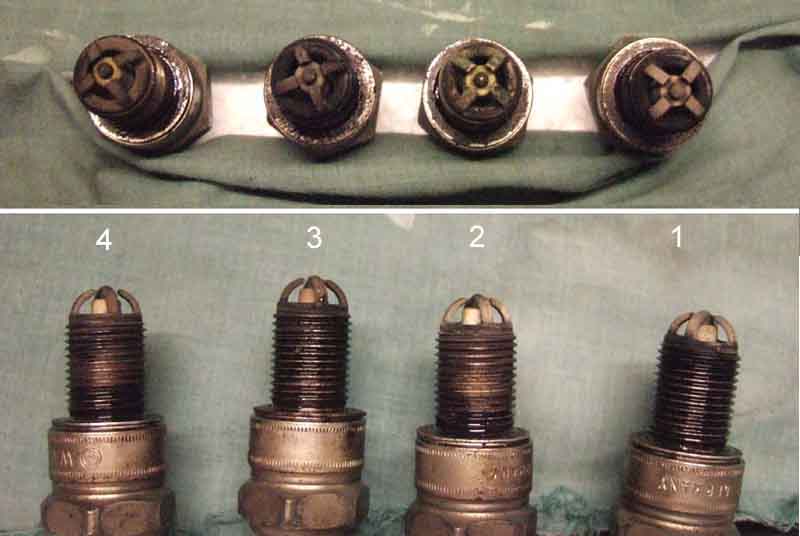 Part of that involves removing all the plugs, so I examined them for colour. They all look pretty good to me, perhaps the back pair are just a smidgen richer. I decided to weaken that carb a tad, and given that it's awkward to turn the HS nuts with the air cleaners on I made a box-spanner, which worked a treat.
December 2016:
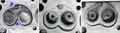
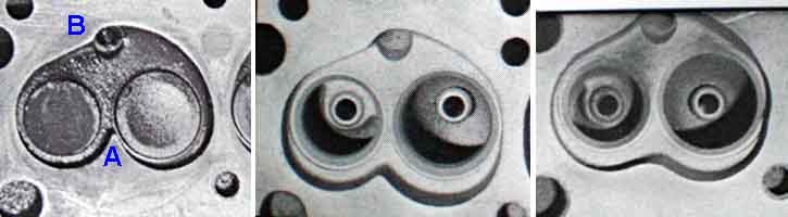 A pal had similar pressurisation of the cooling system to Bee, but like Bee it had been evident for many years without causing any problems. Then he started to get a bit of coolant loss, and several tests culminating in a combustion leak detector in the radiator filler neck confirmed a leak, so head gasket replacement was called for. However he has a supercharger fitted, and after (not too much) pondering decided to have his head modified for the s/c by Peter Burgess as part of the job. Sent the head off, and almost immediately got a call back saying the head was scrap as it was cracked! I put him on to someone who could supply a bare head for just a tenner, which was delivered to Peter Burgess where it was tested, found to be OK, modified, and shipped back to my pal. However on refitting the rocker gear he suddenly realised this was the later head with the offset oil feed hole! See here for info on head types. Another call to Peter Burgess, and another wait for a compatible rocker pedestal to be sent back. After that refitting went OK, and the run-up in the garage to purge the coolant and check for any nasties, before the first test run. He doesn't know whether he had forgotten how fast it used to be over the several weeks the car was off the road, or whether the new head was that much better, but pronounced himself well impressed with the performance. He is planning on putting it on a rolling-road in the Spring, it's a pity he hadn't done it before to get a comparison and see how much he was getting for his several hundred pounds of modified head. As well as flowing the ports, the combustion chamber is also modified (as shown in the attached images). This does reduce the compression ratio slightly but hopefully is more than outweighed by the improved combustion.
- Heads 1: Peter Burgess is the obvious choice for testing, and conversion if sound, £282 plus ARP studs and sundries.
- Heads 2: If Bee's head no good one fairly well-known supplier has brand-new Ivor Searle heads of the correct casting available at £414 inc VAT, plus ARP studs and sundries, but see Engine 2.
- Engine 1: If replacing the studs goes wrong the same supplier has Ivor Searle engines on an exchange basis at £1550 inc VAT plus £420 surcharge, presumably if the old engine can't be reused. And logistically a bigger job to swap engines, meaning Vee will have to be outside in winter for a while.
- Engine 2: Studs ditto, a pal has a rebuilt engine available, only done 500 miles. £400, but will need some work, and the same logistical issues, plus those of getting the engine from Milton Keynes to Solihull.
- Stud removal: Several recommendations, including whacking the end of the stud first, Stilsons (not much room for wielding those in a forest of studs), and a Laser impact stud removal tool that cropped up more than once. Halfords have them for £21, and I have an air-gun, so that gets my vote. Also usable with a breaker bar, but when pulling hard it's going to be difficult not to apply a bending moment that may snap the stud.
- Replacement studs: Also several recommendations NOT to get standard studs from the usual suspects, as they are pretty useless, and to go for ARP instead. Probably talking about £160 instead of £30, but I can't afford the risk of problems refitting.
So one afternoon I start by slackening the bottom hose to rad clip, pushing a screwdriver up the gap, and letting it trickle down a large padded envelope to guide it into a bucket (rad cap removed) while I get on with things. I even spent time undoing the block drain plug (accessed with everything else round it still in-situ), which had wet gunge behind it but only let out a dribble for a couple of seconds. In the event not needed, as normal draining via the bottom hose had lowers the level to several inches below the block anyway. While down by the bottom of the rad I noticed the bottom of the front cover and that part of the sump are oily, so 'while I'm at it' a new front cover gasket and pulley seal. With the system drained it'll be easy to get the rad out and give me more space to work. With the cover off I'll also have to check the timing chain, gears and tensioner as I think the latter is getting slack and rattling a bit. But I'll only delve into that when I know I'm going to be keeping this engine. I also pondered fitting a drain tap to the bottom of the rad as I have a spare block tap. But as my method is easy and clean, and it's not something I plan on doing on a regular basis, I decided against it.
As it's been less than four years since everything came off last time it all came undone without any problems - air-cleaners, carbs, inlet manifold (left attached to the servo hose and servo), exhaust manifold on its pipes wedged away from the head studs with a block of wood without undoing any of the clamps, heater hoses and return pipe, heater tap left on its cable, temp gauge sender, plug leads but plugs left in case I need to crank it to break head-gasket stiction, rocker cover, and start slackening head nuts in sequence. A couple of the rear valves were open, and that end of the head started lifting straight away. With all the nuts off I removed the rocker shaft to lessen the weight - break the stiction to the push-rods as you go, removed the push-rods being careful to leave the cam followers behind and store them in order, and with a bit of wiggling lifted the head straight off. I was surprised the head and block surfaces were clean and the gasket not stuck at all. I was expecting it to be the same as the composite gaskets I last used on the Scimitar, and which are sometime used on the V8s, which bind to the surfaces and need a coolant-less running period to bond them. I did that last time, obviously needn't have bothered!
 So, head off, studs sticking up. Fit the removal tool to the first long stud, hand-tighten, attach air-gun tighten-chatter-chatter-chatter ... and out it screws! Clamped tight onto the stud, so I took it over to the vice to get a Stilsons on the outer part to undo it, hardly a mark on the stud. I could have used the Stilsons to hold the outer part while I reversed the air-gun, but didn't think of that at the time. On to the next stud, and the next, and the next, and so on. Some needed quite a bit more chattering than others, but they all came out - phew! What's more it's taken less than 2 1/2 hours to get them all out from first starting to drain the coolant!!
So next step is to discuss with Peter Burgess options for testing and modifying. He does standard unleaded at £282 inc VAT or Econotune (a bit more poke) at £432, but after pondering I decide on standard as I've never been into performance upgrades - having driven an F1 on track nothing else will ever come close. Booked a day to take it up, Peter checked it over and declared it sound, ditto the rocker gear, so will proceed with a standard unleaded conversion. In the meantime, I removed the front cover to replace the gasket and pulley oil seal, and investigate the timing gear and tensioner.
A warning: Ted Prouten writes on the MGOC forum:
"I have just sent my 12H4736LF COUNTY cylinder head to Peter Burgess for inspection
"For those of you who like me were unaware.
"This is a relatively new cylinder head casting which, because of the tiny ports and the combustion chamber roof which features the seats sunk 1 to 1.5 mm. means it is not suitable for anything but standard leadfree use."
 Late Feb I collect the modified head ... painted a nice shiny black which I'll have to repaint for the Gold Seal engine. He's replaced the rocker shaft for me as it the old one is showing a bit of wear, and supplied a set of good head studs (When I replaced the head gasket I felt some of them were stretching, so wasn't going to use the same ones again). Then we get the snow on top of the below zero temps, so I don't even get it out of the car for a few days until it starts to warm up a bit.
Investigating gold paint at Halfords most seemed to be too coppery compared to the rocker cover I took with me, and settled for a Frord colour as that seemed closest. But when spraying the rocker cover, which was already gold, it was nothing like the colour band on the tin! Realising I could go through two or three tins trying to get a match, it occurred to me (belatedly!) to check the usual suspects. Only Moss has it ... at £17 per can ... gulp, and £10 delivery ... double-gulp! But along the way I decided to replace the manky heat shield as well, which lessened the pain somewhat. Waiting for that I cleaned up the block face, and checked the replacement studs would go into the block as far as the end of the threads. I also masked off the valve area and thermostat housing, plug holes, heater tap location, and manifold face, so was ready to paint by the time it turned up. Impatient as ever, annoyingly the second coat started to go like a crackle finish. I thought it was reacting with the black and it was going back to bare metal, but it was only the second coat. So I left that to dry right off before giving it some more light coats, which has covered it up fairly well. It'll have to do. In the meantime I did the rocker cover again, but I'm not sure it's a terribly good match, its more like a browny-buff colour than gold.
 I wake up on the morning I'm planning to refit the head ... and suddenly realised there are no manifold studs! As they didn't come out easily with double nuts I left them in, but Peter obviously had to remove them to do his stuff. I can't believe I didn't notice it especially when prepping the head for paint when I masked off the ports in one straight strip as there were no studs in the way! More P&P. But despite that the head can go back on - Payen gasket again, and the alternator-side ancillaries, thermostat, housing, cooling and heater hoses. When the studs arrived I was annoyed to discover that after checking manuals and web sites carefully for how many of each length were required I seem to have got them the wrong way round on the order! Should be four long (FHS2515) and two short (FHS2313). Still, the four short ones are just long enough for the long brass nuts. The longer ones are a bit too long for the outer pair in that the plain shank extends just past the face of the flange, but with some thick water pump bolt spacers left over from Vee's engine rebuild plus lock-washers they are fine. Why I didn't think to use the two long in the middle so releasing two of the shorts for the outers I don't know.
With the head on and torqued up I did a quick check/adjust of the rocker clearances to make sure the valves were closing fully - just enough to have a bit of free play. I then did a compression test to check everything was OK before going further - and was taken aback to discover how low and variable they were: 104 136 110 132. But thinking about it if any of the gaps were small especially the inlet it would impact on compression by closing even later in the compression stroke. So I did the gaps again this time setting them correctly at the Rule-Of-Nine point. Compression now noticeably better and even at 125 135 122 150, but as I know I have a 'funny' cam I did them again looking for the point of maximum gap and adjusting there. Another improvement - 138, 150, 124 145, although the one that was highest before was now slightly lower, probably a factor of the gap now being slightly lower at the start/finish of the lobe. All these were done cold of course.
 So then it was a case of plodding through the fittings i.e. temp sender, heater valve, heater hoses, manifolds, heat-shield and spacers, carbs and their plumbing and cables. Then a dry run (no coolant) just to check oil was getting to the rockers. Then fit the rocker cover, fill with coolant, and run up to temperature. Looking all round, over and under and all looks good. But peeing down so a road test will have to wait for another day. A couple of days later dry enough for a short run, then next day a longer one of over an hour and all looks well so far. Did a hot compression test - dry was 157 157 152 162 and wet 170 170 156 165. 1 & 2 good showing a good rise, less so 3 and 4 when the dry figures are pretty close. However Willy Revit points out that even on the HC pistons there is a small dish so you have to be sure to squirt the oil at the bore with a can rather than just dribbling it in to lie in the middle.
Valve Clearances
Originally valves were used with double-springs, a shroud to locate the inner spring, and a spring-clip round the top of the collets but in 1969 part-way through 18GD production (Clausager) or the start of the 18V (Parts Catalogue) single springs were used with no shroud or spring-clip. The cap, collets and 'packing-ring' (oil seal) are shown as being the same throughout production.
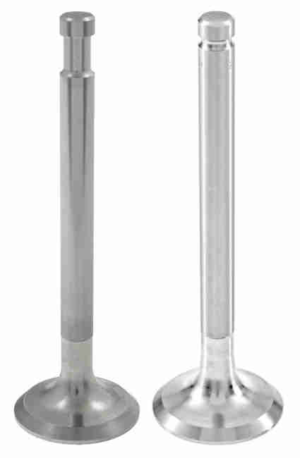 Double-spring valves have a recess the length of the collet and from drawings the packing-ring sits at the bottom of that. Single-spring valves only have a narrow groove for a projection at the top of the collets, so the packing ring is on a larger diameter part of the stem than previously. Other than that the valves remained the same except for 1972 to the start of rubber bumpers when a larger diameter inlet was used. Double-spring valves are 12H435 inlet and 12H436 exhaust, single spring valves are 12H4211 small inlet, 12H2520 large inlet and CAM1717 exhaust.
Valve Stem Oil Seals June 2023
I've had an email from someone who wrote:
"In the case of the inlet valve stem do they also require an oil film for normal operation? I see people fitting additional top hat seals on the guides to reduce oil being sucked down by the inlet vacuum pressure over time. Would this reduction in oil flow not cause additional guide wear? Also the seals sold by the usual vendors look really poor quality as compared to Viton Seals used in the USA. I believe there is an Elring seal which will fit.
"I am also confused as to how the lead in original leaded fuel acted as a guide lubricant.
"I am just about to put the head back together. Should I lubricate all of the valve stems or just the exhaust or assemble it dry? The Leyland workshop manual does not mention lubrication during assembly."
I'm no expert on the subject but I will say that I don't see how leaded fuel had any effect on valve stems, it was the seats that the lead protected by cushioning the impact as the valves closed. The rest is based on my thoughts from a common-sense point of view.
When people say the MGB needs something that the factory never provided the first thing I say is "What problem is it solving?". Valve stem/guide wear and high oil consumption/smoking from it can't really be an issue or our cars would be trailing clouds of smoke, never mind the millions of other BL models that used A and B-series from way back before the MGB. They rarely do based on my experience of more than 30 years of running with groups of other MGB owners never mind my own rear-view mirror. Having said that all engines wear over time, valve stems and guides are no different to anything else that moves in the engine, and when they are worn you will get puffs of smoke after running downhill with the throttle closed then opening it, or idling for a period then blipping the throttle, or simply changing gear and reopening the throttle in more severe cases.
The WSM calls the O-rings 'packing rings' not 'oil seals' as suppliers do. The WSM does say that when reassembling a head "new packing rings should be used or oil sealing may suffer" and head gasket kits do seem to include them. Looking at the drawings the packing ring would need to be sandwiched between the bottom of the collets and the top of the cap to do any good, such that in general oil from the rockers runs off the cap and down the coils of the spring instead of running down the stem to the guide. Given the contact surface area between stem and guide and the small clearance I don't think the oil does much to aid cooling, but of course it will reduce wear from sliding friction so some must be needed, and sucked down from above. There has to be some clearance - I understand some early unleaded conversions had problems because they didn't allow enough for the materials being used and how they reacted to heat and you could get sticking valves. As said above it's the depression in the cylinder as the piston goes down drawing in mixture that will suck oil down, and the top of the head should be swimming in it. There will always be people that swear by alternatives, and in my opinion whilst the top-hat type may well reduce oil consumption with worn stems and guides, by keeping oil away from the top of unworn guides they may well be accelerating wear.
It's always been said that some upper cylinder lubrication is a good thing, which is why in days of yore people used a shot of Redex with each gallon of fuel purchased. It's also been said that lower piston rings should not be too effective at scraping the oil off the cylinder walls as the top ring won't get any and will wear more quickly, and the bore.
I wouldn't use anything other than the standard packing ring (WSM advises soaking it in oil before use). I would put some oil on all the valve stems prior to fitting to act as initial lubrication, it makes sense as with any other part moving against something else, and it can take some time for oil to get all the way through the rocker gear. As said the WSM makes no mention of oiling them, but then it doesn't say anything about lubricating the big-ends and mains on assembly either.
'Rocking', or 'On the rock' method
These are best adjusted cold for consistency (even though you might be tempted to adjust hot in the winter for comfort's sake!) to .015" for both intake and exhaust on all 4-cylinder engines. If you do decide to adjust hot it is .013", but bear in mind the engine will be cooling all the time you are doing it. Adjusting them with the engine running is very slap-dash and can damage the feelers. One potential problem using feeler gauges is that the valve stem that contacts the rocker is much narrower than the rocker pad, which are narrower than the steel shim feeler gauges. On older engines the valve stem can wear a shallow groove in the rocker pad, the steel shim feeler gauges bridge this, so you end up with a gap that is .015" plus the amount of wear in the rocker pad which will lead to reduced valve opening and noisy tappets. One way to eliminate this is to use wire feeler gauges if you can get them, another is to use the Gunson's ClikAdjust (prices vary!), but see these opinions which seem to fall on the side of "it isn't worth it" (I've never used one, did try a Colortune many years ago but found it much more difficult to judge mixture than with the lifting pins, have got an EeziBleed which is useful for a full fluid change but not good enough for bleeding a system after work - either brake or clutch, and have got a GasTester which seemed OK to begin with but has now gone way out of calibration range and the reading varies wildly with slight changes in orientation, and did have a digital MultiTester (?) which was fine but packed up after a few years use (but then so did a Draper and much sooner)).
For many years getting consistent results on my 4-cylinder roadster had seemed impossible - I would adjust them all using the 'Rule of Nine' then go through them again to recheck and some of them would be incorrect. So I would adjust them again, rotate again, and they would be out again! It took me some years to realise that at the strict 'Rule-of-Nine' (RON) point some of the gaps were still changing. And unless I stopped the crank at the exact same point for each valve each time they could vary significantly between tests. So instead of using the strict RON point I just used it as a starting point, and looked for the point of greatest gap on each valve either side of that. On valves 6 and 8 this proved to be significantly after RON and on valve 7 significantly before. What this says about my cam and cam bearings I am not sure, but the tappets are noticeably quieter, and 5000 miles on the gaps are still the same indicating that I am not getting recession or burning.
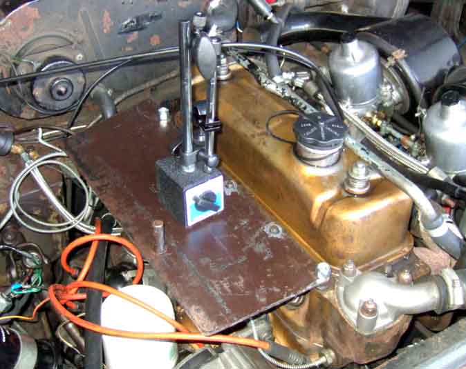 When a pal got a dial gauge and a magnetic base, I decided to see what that showed as far as the clearances varying as the engine was turned over. I had a chunk of 1/10" steel plate that was as long as the head and several inches wide, and drilled five holes in one long edge to fit over the exposed head studs and nuts on the alternator side of the engine. Note that the middle three studs are spaced back a little compared to the other two. Even with the thickness of this plate there were enough head stud threads showing to get additional nuts on, and hold the plate firmly.
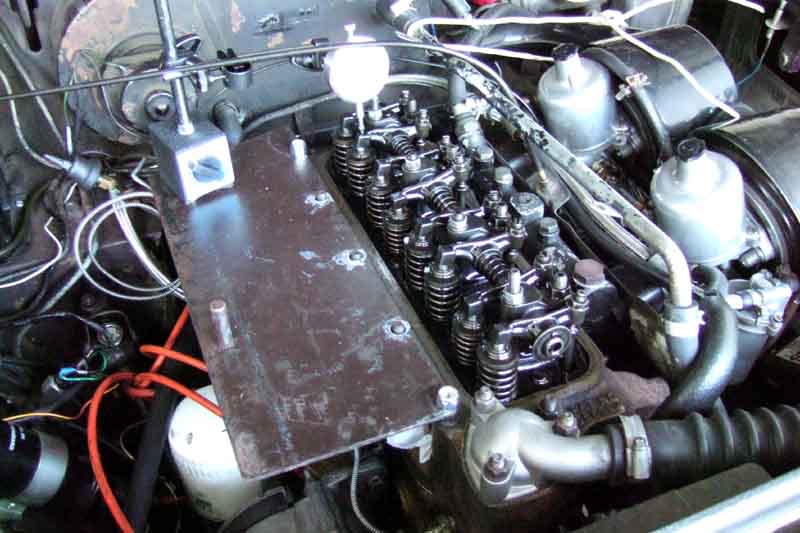 With the rocker cover removed and the magnetic base arms articulated to press the dial gauge plunger down onto the valve-end of a rocker, I was ready to go. I know the rear three valves are the odd ones, the front ones less so, so concentrated on those. The crank pulley nut is only really accessible from under the car, but I don't fancy continually getting up and down for each small movement of the engine. Normally I put the gearbox into 4th, then by pushing the top of the off-side tyre backwards or forwards I can nudge the engine round. But with the V8 dismantled and many parts in the garage, behind Bee, and the full-length ramps positioned half-way down the garage, Bee's rear wheels are only just on the ramps. To use the tyre nudge method Bee would have to be outside, but with the changeable weather at the moment I didn't want to be caught having to drive her back into the garage and get the rear wheels up on the ramps with the rocker cover off. Plugs out, I can easily turn the engine backwards by pressing down on the fan belt between water pump and alternator, but can't turn it forwards. However a spanner on the alternator pulley nut will turn the engine forwards ... but not backwards! So have to keep switching between the two methods when comparing clearances with only small movements of the engine.
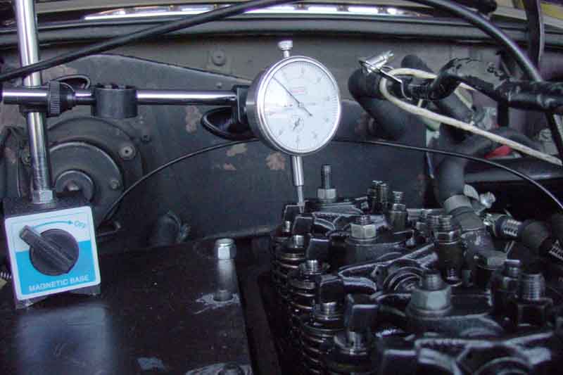 It's quite fiddly, turning the engine bit by bit, pressing the rocker down onto the push-rod each time, taking pictures, and making notes - easy to get confused as to what goes with what. It would be much easier with two, but there we are. It would also be easier if I could rig something up like a strong spring or heavy weight that would continually press down on the push-rod end of the rocker as it went up and down, that's a future 'enhancement'. The upshot is that the dial gauge confirms that the clearance is greater several engine degrees away from the strict rule-of-nine point, but even more interesting is that it suddenly gets a couple of thou greater still immediately before it starts going down. So maybe I need to check in a lot more places between just fully up and just starting to go down, and not simply a little way either side of the rule-of-nine point. However I would need to be sure that didn't mean the gap closed up during the expansion and exhaust phases, which could burn the valves and seats.
Update January 2011:
'Rule of Nine' method
 The Rule of Nine simply provides a clear visual pointer from another valve to adjust its partner valve without knowing what angle the crankshaft or camshaft are at. For example adjusting 1 when 8 is fully down (which is the usual way this method is described), 6 when 3 is fully down, and so on. Each of these partners is the same type of valve i.e. both 1 and 9 are exhausts, and both 3 and 6 are inlets. They are always on the partner cylinder, so all the Rule of Nine is doing is picking an adjustment point for each valve in turn when its partner valve is fully down or 'rocked', it's just a different arbitrary point on the back of the cam to the other method. In fact anywhere the partner valve has opened the valve would be a suitable point, so perhaps the definition of Rule Of Nine should be 'anywhere the partner valve is down', instead of 'when the partner valve is fully down'. Also as you turn the engine if you look for any valve going down and adjust its partner, rather than trying to work through the engine from front to back sequentially, it will still only take two full turns of the crank.
But in theory a valve can be adjusted anywhere on the back of the lobe, and for a portion more either side of that, as each lobe on the standard cam has a duration of 252 crankshaft degrees. This is 126 camshaft degrees which leaves nearly 234 degrees of camshaft rotation, or 117 degrees of crankshaft rotation, where a particular valve could be adjusted. Both valves are fully closed for 253 crankshaft degrees, so you can adjust both of them at the same time with the crank anywhere from 51 degrees before bottom dead centre to 56 degrees after bottom dead centre, with an allowance each side for the valve to be fully off the slope of the lobe and hence the clearance at its maximum. And this leads on to the 'rocking' method.
'Rocking', or 'On the rock' method: March 2020
I've seen references to this method for a long time - usually from Americans, never explaining what it was, and I'd never bothered to find out. Then someone wrote to me suggesting this method would address the 'largest gap' problem, but it doesn't.
 'Rocking' refers to the rockers, but it doesn't mean when they are able to 'rock' back and fore through the valve clearance, quite the opposite. It means when they are depressing a valve so NOT rocking! You turn the engine until both valves on a particular cylinder are partially open, which puts that piston close to TDC on its exhaust stroke, where its inlet valve has just opened while at the same time its exhaust valve hasn't yet closed. On a 4-cylinder 4-stroke engine there will be another piston - the partner piston - at the top of its compression stroke, which will have both valves fully closed and so can be adjusted. On the MGB cylinders 1 and 4 are partners, and cylinders 2 and 3. So with both valves partly open on, say, cylinder 1, you can adjust both valves on cylinder 4, and so on i.e Rule of Five!
So on the face of it this is easier as you can adjust two valves at a time, with only four movements of the engine through two full turns of the crank, instead of one valve at a time and hence a lot more movements. That is true, but both valves are only partially open for 37 degrees of crank movement, so when turning the engine to find this point one has to look for when two valves on one cylinder are partially open - one having just started to open and the other just short of closing - and stop within that band. If you have the plugs out to make turning the engine easier then just look in the plug holes for two pistons at the top then adjust the other two.
December 2021 And because of the way the valves work at bottom dead-centre you can adjust two more valves at that point making four altogether in one go, only needing one full turn between adjustment points.
If you have a straightforward cam where the clearances are constant throughout the back of each lobe then all three methods will give exactly the same results. But if you have a 'funny' cam where the clearances are changing when in theory they shouldn't be, then neither will find the point of maximum gap except by coincidence. For example only one of mine is at the strict i.e. fully down Rule of Nine point, so I spent some time going through each of mine with a dial gauge looking for the point of greatest gap, noted where other valves were at that point as a reference, and now I can go straight to that point for routine checking using this chart. Since doing that they are consistent, needing no adjustment from one years end to the next, and in 2023 checking them for the first time in probably four years and they only needed closing up by a tiny amount.
Rockers December 2017
Rocker-valve Alignment
Valve Clearances
Running out of adjustment?
Rocker Cover
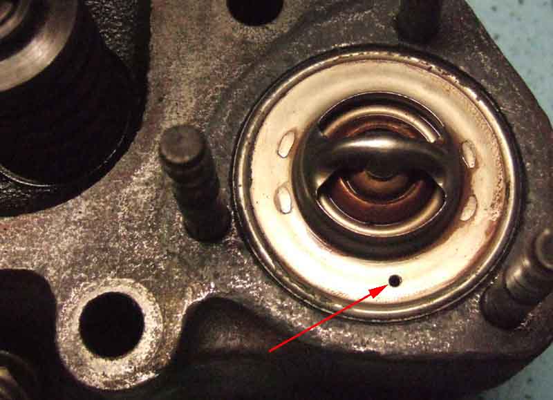
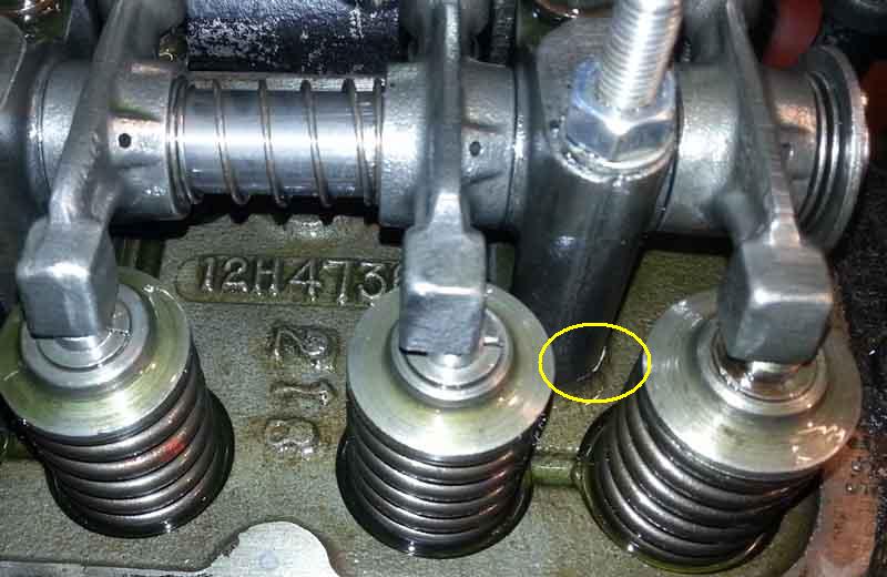
Rocker oil-feed: December 2021: The oil feed for the rockers comes up through the rear-most pedestal, and an important thing to note is that the oil feed hole changed position in both the head and the pedestal on rubber bumper cars.
Rocker-valve alignment: Andrew Robinson emailed to ask my opinion on his rocker to valve alignment, as No.2 seemed particularly out and the rocker pad didn't fully cover the end of the valve stem. He was concerned that this was resulting in unbalanced forces which would cause rapid wear at various places in the valve train. The engine has only done 2k since a professional rebuild and wanted to avoid such wear if at all possible.
Googling this seems to be a not uncommon problem, especially with replacement pedestals. Several said theirs was the same and hadn't caused a problem, and one suggestion was to remove the rocker assembly and machine the pedestals one side and shim the other to get the rockers exactly in line with the valves. But this is quite a big job, and would need all the head nuts to be slackened in the usual order as if one were removing the head, and probably to remove the head and replace the gasket.
 Looking at his picture there was a sliver of machined head visible in front of the pedestal, but not behind, and the nuts and washers also seemed to be more to the forward face that the rear, as if the holes in the pedestal were larger than they needed to be giving some scope for fore and aft positioning of the pedestal on the head. I suggested that he could slacken the rocker cover stud nut first, then the head nut at the rear of the pedestal, then he might be able to quickly move the pedestal forwards a bit and retighten the head nut without compromising the head or gasket. He did, and got just enough movement for the rocker pad to completely cover the valve stem. Still offset to some extent, but the rocker web does now seem to be in line with the stem, so the forces should be balanced even if the positioning isn't exact.
Subsequently it occurred to me that if one were to slacken all the adjusters right off, and remove the split-pin at one end of the shaft, one might be able to push the shaft back (or forwards depending on which rockers needed adjustment), catching all the bits and keeping them in order for reassembly, to remove No.2 rocker and machine the appropriate amount off the front face to bring it fully into line. His No.1 rockers also seems a bit off, but not as much as No.2, and that could be shimmed on its rear face.
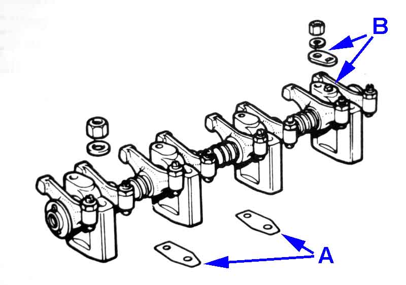 Later engines have a shim under each of the middle two pedestals to move their shaft holes fractionally out of line with the outer two. This means that when all are bolted down the shaft is gripped firmly and prevents the shaft from fidgeting in the pedestals and causing wear there, and noise. That deliberate misalignment may be enough to prevent you sliding the shaft out of the rockers while the pedestals are bolted down - or back in once out, as suggested above. There is no date for the provision of the pedestal shims (12H 3960, 2 off), the Parts Catalogue lists them for five-main engines but not for three-main, and the WSM has section A.32 'Rocker Assembly (Later engines)' that states they should be fitted to early engines on reassembly. However some with later engines say theirs doesn't have them, so they may well have been lost on reassembly. There is also some debate about what they are for and even whether they are needed at all. So as well as people wanting to provide things the factory didn't e.g. valve stem seals they also say things the factory did provide are not needed.
 Note that of the two studs in each rocker pedestal the ones nearest the valves - two of which are used to secure the rocker cover - can have the nuts removed (perhaps for stud replacement) without affecting the head gasket. But the four between the pushrods, together with the other round the head outside the rocker cover, should only be slackened and retightened using the correct sequence.
Running out of adjustment? June 2022
 Jonathan Bawden posted on the MGOC forum that he seemed to be running out of adjustment on one of his rockers, which could indicate all sorts of problems. However John Pinna spotted that they were two different rockers!
Rocker Cover Added September 2007:
Alloy Rocker Cover
Decals
Lots of discussion on rocker cover oil leaks in the various fora. One frequent observation is that if the covers are overtightened, then they will distort and leak, and further tightening makes them leak even more. Fair enough, but the later 18GD etc. and 18V engines have a different rocker cover nut which is much deeper than it needs to be which seems as if it was originally intended to prevent over-tightening, by tightening down onto the top of the rocker pedestal nut. However unless everything else is present and of the correct thickness, including the rubber washer (between cup washer and top of the rocker cover, 12A1358) and the cork gasket, it limits how much pressure can be applied to the cover gasket, and insufficient pressure together with porosity of cork gaskets will cause leaks.
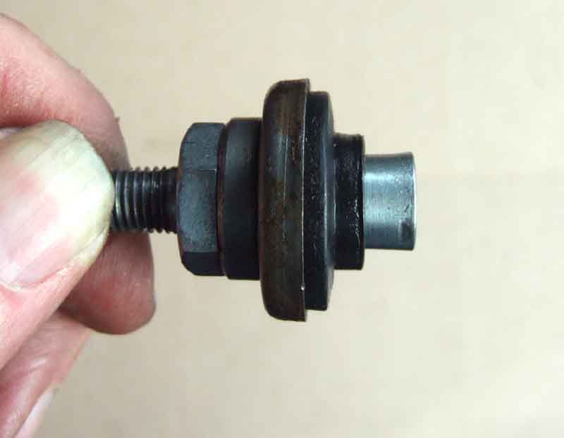 The later rocker cover nuts, as well as having the stud on top of the nut for the heater return pipe, has a deeper cylindrical portion below the hexagonal section. This passes through a 1/8" spacer, cup washer, rubber bush and rocker cover onto the long cylinder head studs used to secure the rocker gear. The rubber bush performs two functions - it seals the fixing holes in the cover to prevent leaks, and also applies pressure to the cover and from there to the cover gasket and head. Old rubber washers compress and harden with age and so reduce the pressure applied to the cover gasket. Old cork gaskets similarly compress, and can rarely be reused successfully once disturbed, even if it was oil-tight before.
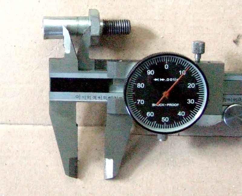 On my engine once the cover nut has taken up all the free play between it and the top of the spacer, it can only be tightened one more turn before the bottom of the cover nut contacts the top of the rocker gear nut. This is with new rubber washers and new cork gaskets. Even gluing the cork gasket into the cover, and using Hermetite Red as the seal to the head, I still get weeping from the rear of the cover. Although this results in only an occasional drop of oil on the floor I still don't like it, and I have had to put 2 or 3 thicknesses of gasket card between the cup washers and rubber washers to get a seal.
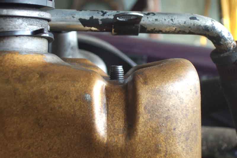 In discussions some have avowed that this is because it has been overtightened in the past and buckled the cover, the cover nuts should never contact the rocker gear nuts. But my cover is perfectly square and symmetrical. One poster stated that, with the exception of the oil filler, you should be able to lay a straight-edge across the top of the cover and have no gaps. Now straight away this is incorrect as the cup and rubber washers sit in recesses, that extend as grooves down the side of the cover. I can't for the life of me see why the cylindrical portion of the cover nut should be made so much deeper than the cup and rubber washers, unless it was designed to bolt down to the rocker gear nut and so prevent overtightening. I've no experience of the 3-bearing and 18GD engines but they have a different rocker cover nut which doesn't seem so deep and with those I can imagine they could be tightened so much they distort the cover. I also don't see how on the one hand overtightening the nuts overcomes the natural springiness of the pressed steel cover enough to cause distortion, but in my case at least adding more packing to apply more pressure stops the leaks. The only way the cover could have been distorted so much that there is now only one turn of the nut available before it 'bottoms' is if a lot of extra packing i.e. several thick washers had been fitted in the past. But there weren't any when I got the car, it didn't start leaking until I replaced the rubber washers and cork gasket, and the old ones weren't bonded. But then I only have a sample of one.
The upshot is that for the moment I'm leaving things as they are. I'm not going to try and 'uncrush' the cover as that almost certainly will distort the cover beyond sealing, and at the moment nipping the nuts down as far as they will go gives me a decent seal without any further risk of overtightening and distortion. I'd still be interested to see how much the stud does or doesn't protrude on other engines, though, and get the measurement from the face of the flange the cork gasket sits against to the recess the rubber washer sits in.
July 2014:
I've just had to replace the head gasket, and whilst cleaning the rocker cover I suddenly realised the holes in the top where the rubber seals fit were bowed instead of flat. So the rubber seal rocked in them, and it was only sealing in the fore and aft position, and not at the sides. So that was where the oil had probably been coming from all these years, but wasn't visible until it had run down as far as the head. Pondered a while how to deal with that, and came up with squeezing the cover in a vice, with appropriately-sized sockets on both sides of the holes. First attempt at just clamping them up still left them slightly bowed, so I clamped them up again and rocked the cover top and bottom and side to side, which wiggled the holes nice and flat.
Oil Filler Cap: January 2022 18G engines had a metal oil filler cap that was not ventilated. From 18GA engines on positive crankcase ventilation was used with a plastic oil filler cap that was ventilated and filtered on RHD cars and LHD cars up to 1970. From 1970 North American cars, and from 1977 all LHD, had an evaporative loss control system that used a plastic non-vented oil filler cap. V8s always had a sealed oil filler cap. For more information see Crankcase Breathing.
Alloy Rocker Cover: January 2022 Alloy rocker covers are quite popular - for 'bling' mainly, they are claimed to reduce tappet noise but others claim they don't - and probably will have a shiny oil filler cap. These may or may not be ventilated - with a visible hole on the top, but they may also be unventilated, or ventilated with a concealed hole. Some of these with a visible hole are advertised as for 62 to 64 cars i.e. the 18G engine but would not be 'correct' although probably won't do any harm. Shiny caps probably don't have a filter as they are much closer to the cover than ventilated and filtered, which may not be ideal with the later positive crankcase ventilation systems that are pulling air through the cap all the time. Alloy rocker covers do not seem to have the gasket retainers that the pressed metal do which means the gasket has to be glued to the cover to ensure it stays in place as the cover is fitted, needing to be scraped off when the gasket is replaced.