
Overdrive - D-Type (to 67)
A description of the vacuum switch, its component parts and its calibration can be found here.
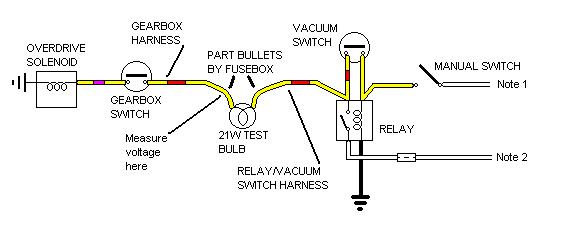
 Schematic")
Note 1: On 62-64 cars the manual switch is wired back to the ignition switch. On 65 to 67 cars it is wired to terminal 3 of the fusebox.
Note 2: On 62-64 cars the relay contact is wired back to terminal 3 of the fusebox. On 65-67 cars it is wired to a 6-way bullet connector in the mass where the main, rear, gearbox and OD harness all join together near the bulkhead.
When the manual switch is closed the relay is operated, and the relay contact energises the solenoid via the gearbox switch if closed, and overdrive is engaged. At this point the condition of the vacuum switch - open or closed - is immaterial.
Assume now that with overdrive engaged the engine is doing high rpms but the throttle is closed i.e. it is on the overrun. This will create a high vacuum in the inlet manifold which will close the vacuum switch. If the driver now opens the manual switch, the vacuum switch being closed will continue to maintain a 12v supply to the relay winding from the relay contact, independently of the manual switch, so the relay remains operated, the overdrive remains engaged, regardless of the fact that the manual switch has been turned off.
Imagine now that either the speed of the car has slowed so that the engine revs are closer to idle, or the clutch is dipped so allowing the revs to fall to idle, or the throttle is opened again. In all cases the vacuum in the inlet manifold will reduce, allowing the vacuum switch to open. This causes the relay to release (the manual switch is already open) and its contact disconnects 12v from the overdrive solenoid so disengaging overdrive.
Fusing: A single fuse could be inserted at point A where the relay and vacuum switch harness joins the gearbox harness with two yellow/reds. But to protect the gearbox and vacuum switch harness as well one would need to be inserted at point B (either at the bullet connector where the main harness joins the relay and vacuum-switch sub-harness with two yellows, or at the manual switch) AND at point C leading to the white in the relay and vacuum-switch sub-harness.
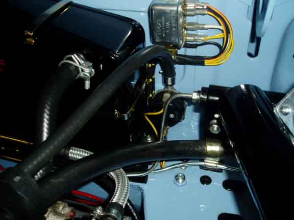
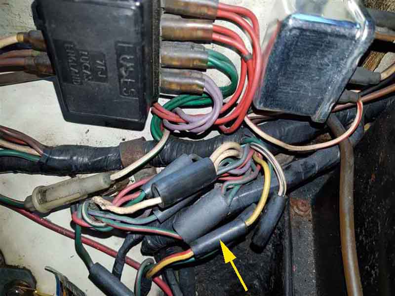
This picture shows a yellow wire from the manual switch coming out of the main harness joined to a yellow/red going into the gearbox harness as it would be on a 4-synch car. For the 3-synch with relay and vacuum-switch the yellow from the main harness will go to another yellow in the relay and vacuum-switch sub-harness. Insert fuse B here. Above it are three whites, on the 3-synch there will be a fourth white going to the relay and vacuum-switch sub-harness, insert fuse C here.(Image by David Farrar on the MGOC Forum)
Update January 2008 I was under the impression that the vacuum switch was to prevent OD being disengaged under conditions of "high manifold vacuum" (Leyland Workshop Manual) i.e. to prevent high reverse torque from damaging the OD. But info from Bruce Cunha indicates that the vacuum switch only opens at manifold depressions lower than 7 in. Hg., and so OD could only be switched out if accelerating significantly, i.e. a bit like a kick-down on an auto box. But the Workshop Manual talks in terms of it delaying the change "until the engine takes up the drive", which implies light acceleration with the inlet manifold depression significantly above 7 in. Hg. Subsequent discussion with the designer of the transmission system for the MGB confirmed that the vacuum switch was indeed intended to prevent disengagement unless the car was accelerating, but to give a smoother disengagement rather than to prevent damage. However they found the vacuum switches were unreliable and so deleted them opting for 'driver education' instead. However my 73 Drivers handbook says it (the LH-type) can be engaged and disengaged accelerating or decelerating, just not to depress the clutch while doing either.
Of course, if the gearbox should be taken out of an overdrive gear the gearbox switch will ensure that overdrive is disengaged instantly, regardless of the position of the manual or vacuum switches. 'Normal' gear changes, say from 3rd to 2nd, will usually allow the overdrive to disengage safely and not encounter the mechanical stresses that the vacuum switch and relay are designed to avoid.
The vacuum switch on its own cannot operate the relay and so cause overdrive to be engaged, the manual switch must be closed first.
The other thing to be aware of is that the manual switch will operate the relay, and the vacuum switch will keep the relay operated under conditions of high manifold vacuum even if the manual switch is turned off, when the gearbox is not in an overdrive gear. All this means is that when an overdrive gear is selected the solenoid will be energised and overdrive engaged as normal.
The later LH-type overdrive does not have this vacuum switch and relay, presumably the designers feel it is strong enough to take disengagement under conditions of high manifold vacuum without damage. Also the current taken by the LH solenoid is much less, so the relay is not required for that reason either.
February 2014: It should also be noted that on some makes and models with this overdrive unit the relay was provided even when the vacuum switch wasn't. This is because the initial current from the solenoid - the 'pull-in' current - is several amps, which is more than the rating of the manual switch. Once the solenoid has operated the pull-in coil is disconnected leaving just the 'hold-in' winding, which only takes from 1 to 2 amps. Whilst the standard overdrive manual switch will operate the solenoid without either relay or vacuum switch, the high initial current can result in premature switch failure, and some have reported this if they haven't bothered to fit the relay because they couldn't obtain a vacuum switch. However if you engage the manual switch with a closed throttle, i.e. vacuum switch contact closed, in an OD gear, it is initially the manual switch that powers both the relay and the solenoid, which initially takes a high 17 amps of current. It is only when the relay has operated that its contact takes over the load of the solenoid. It's said that the manual switch isn't up to the job of powering the solenoid, and I'm aware of at least one person who has had a couple of manual switch failures when using the circuit without the relay and solenoid. Some applications of this OD still had the relay when they didn't have the vacuum switch, which tends to support that. Ideally the vacuum switch would have a series diode, so current could only flow back from the contact, through the vacuum switch, to the relay winding to keep it operated, and not allow current to flow the other way i.e. from the manual switch, through the closed vacuum switch, to the solenoid, but I doubt suitable semiconductor diodes were commonly available at that time. Another option would be a dual-make or 'split-charge' relay, with the solenoid on one output contact and the vacuum switch on the other, as with the relay released the two output contacts are isolated from each other so current couldn't flow from the vacuum switch to the solenoid. But again these weren't available at the time, only subsequently with 'cube' relays i.e. Lucas SRB630 or the Bosch with 87 and 87b contacts. The LH solenoid doesn't have this two-stage operation, only takes 1 amp, and so the manual switch doesn't need a relay.
Electrically testing the circuit:
Note 1: On 62-64 cars the manual switch is wired back to the ignition switch. On 65 to 67 cars it is wired to terminal 3 of the fusebox.
Note 2: On 62-64 cars the relay contact is wired back to terminal 3 of the fusebox. On 65-67 cars it is wired to a 6-way bullet connector in the mass where the main, rear, gearbox and OD harness all join together near the bulkhead.
Locate the 2-way bullet connector where the yellow/red from the relay/vacuum switch sub-harness joins the gearbox harness. Part the connector, and insert a 21w indicator bulb in series with the two wires. With the ignition on, an overdrive gear selected, and the manual switch turned on the bulb should glow at near full brilliance, showing the low-resistance pull-in winding is in circuit. If it only glows at half brilliance the implication is that the pull-in winding or its normally closed switch are open-circuit, and only the higher resistance hold-in winding is in circuit. If the bulb doesn't glow at all the circuit is completely open, i.e. it could be a problem in the wiring or the gearbox switch as well as the solenoid. Even if the electrical tests are good, the solenoid plunger could still be jammed. Note that the plunger will not operate with the test bulb in series, this is just an electrical continuity test, not a functional test of the overdrive unit as a whole.
It should be noted that if you intend to fuse the overdrive circuit to protect the wiring, both the white feeds from the fusebox to the manual switch and the relay should be fused.
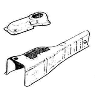
The location of the overdrive and reverse light switches:
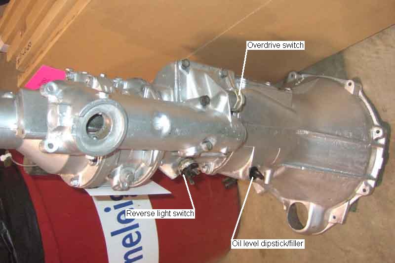
Showing the large access panel on top of the 3-sync tunnel (left), as opposed to the small one on the 4-sync. This should be enough to get at both the OD and reverse light switches on the 3-synch, whereas on the 4-synch the rear crossmember and back of the gearbox has to be dropped as well. Image from Moss Europe Incidentally the 4-synch removable panel is shown the wrong way round by Moss with the hole for the gear lever at the front, it is towards the rear as shown here.
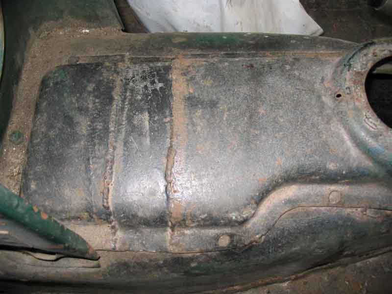
3-synch: The main reason for this picture was to show how the cover is moved backwards when a 4-synch gearbox is fitted to the earlier car. You can see the screws in the forward section, and the holes in the rear section which were for the remainder of the screws originally, but has been tack-welded in place.
For information on the 4-synch switch see here.