The 'Crack of Doom'
Drain Holes
Hinges
Hanging and Adjustment
Key lock
External Handle
Latch August 2010
Door Pulls May 2011
Door Cards November 2014
Door Seals February 2019
Drop-glass and Regulator
Quarter-lights
Tread Plates July 2019
Mirrors
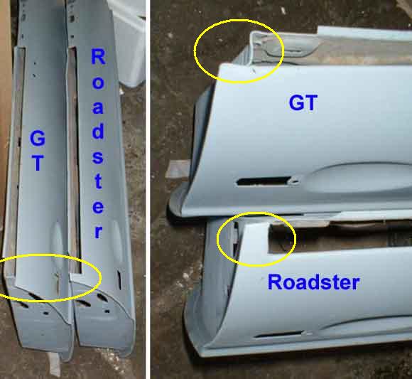 The most obvious difference between the doors is at the top of the skin above the latch. The roadster skin comes all the way up past the drop-glass slot to the inner skin, whereas the GT stops at the beginning of the slot. This is to do with the GT roof-line being higher, hence the glass and quarter-light are taller, but there is the same depth inside the door for the lowered glass. That would leave the GT glass sticking out of the top of the door by about 1/2" (the roadster glass is about 1/2" lower than the top of the door), so to cover that the outer seal is fitted on top of a bright trim strip that sits on top of the door, and the glass drops out of sight on both doors. However I'm not sure why this required the change in the door skin, as it is it leaves a gap on the GT door below the trim strip and seal which has to be covered with a stainless finisher.
It's said that this is the only difference, other than that the doors are interchangeable, with the modification from one to the other relatively easy to make. Remember that there are very significant differences between Mk1 and Mk2 doors, windows and locking furniture, and converting between Mk1 and Mk2 is a very different proposition.
 When I bought 'Bee' the drivers door had the 'crack of doom' which is split at the top of the door skin near the front door glass channel. After much study I decided there was a design weakness in the door skin, in that the flange that supports the outer rubber seal ends just before the front door glass channel. The MGB doesn't have much scuttle-shake - where the screen wobbles from side to side over rough surfaces - but there is some. If this is allowed to waggle the quarter-light frames from side to side, that's when you get splitting of the door skins. It's been claimed that this splitting is caused by using the top of the door to close it instead of using the internal handle, however that just doesn't hold water. If that were the case I'd expect GTs to show it more than roadsters given that there were significantly more of them sold in the UK than roadsters - 65,000 to 50,000, and they rarely do. Also if you do close a roadster door using the top of the door you are likely to be pulling on the waist rail, and that is attached to the inner skin not the outer. Whereas if you do it on a GT you would probably be using the finisher that carries the outer seal, which is attached to the outer skin. There are cases where it has happened to a GT, but that is more likely to be caused by pulling on the door by the raised drop-glass or top of the quarter-light as much as anything, or where the long leg on the quarter-light is incorrectly adjusted and it is being pushed outwards by the door seal every time you close the door.
To strengthen the skin I welded a small piece in such that it extended the flange alongside the channel and round the front, meeting up with another flange. The picture from Lyndsay Porters Guide shows the area quite well. The first shows the area that splits (arrowed), and the second where I have extended the flange in yellow and blue (false colour). Subsequently I saw a Heritage door that seemed to be constructed in just this manner (December 2018: However in this Heritage video with an unknown filming date (ignore the posted date) the outer skin seems unchanged, at 4:33). I MIG-welded the crack, and used a large oval plate behind the door skin to support the door mirror. It has a slightly larger radius than the door skin, so bracing the mirror over a large area.
Update January 2005: During a thread on this subject in a mailing list Rich Chrysler posted the text of a BMC (Canada) Technical Service Bulletin from 1963 showing this problem and saying a production change was being made. My first thought was "well, they never did" but by the date of the bulletin the MGB had only been in production little more than a year and less than 20,000 had been made, so the problem must have been serious. 30 years and 500,000 cars later we know it still occurs, but most cars don't have it, so I'm thinking that they did make a change which considerably improved things, but did not completely eliminate it. The drawing in the bulletin shows three edges joining at a single point, whereas the Porter picture shows a slightly different arrangement, and the former would be more prone to cracking in my view, however the drawing may just be 'artistic licence'. For interest a scan of the complete document can be seen by clicking here.
Following repair it is vital that the way the screen and quarter-light interface with each other is correct to minimise any reoccurrence. 1. The front of the quarter-light frame must only just touch the bulbous part of the pillar seal and not depress it, and 2. There must be a small clearance between the side of the quarter-light frame and the thin part of the pillar seal. These two adjustments allow the quarter-light frames to be kept static even if when the screen wobbles.
1. The adjustment of the front of the quarter-light frame to the bulbous part of the pillar seal is done by adjusting the fore and aft position of the screen, and its rake. Other than moving the doors on the hinges (which should be done first to get the correct shut-lines) there is no other provision for fore and aft adjustment of the quarter-lights i.e. within the doors. Note that old seals can be hard and shiny, allowing some 'slip' between frame and rubber. However new rubber is 'sticky' hence the need that the two only just touch,
2. The adjustment of the side of the quarter-light frames to the thin part of the pillar seal to get a small clearance is done partly with screen leg shims to centralise the screen relative to the quarter-lights, and by an adjustment on the long leg of the quarter-light frame (except on early cars). This goes down to a slotted bracket at the lower front corner of the door, and the stud in the leg moves in a slot in the bracket to move the leg between the inner and outer door skins, which moves the top of the quarter-light closer to and further away from the thin lip of the pillar seal. Adjust the long leg stud to get an equal clearance all the way up, as far as possible.
Drain Holes November 2016:
 There should be three drain holes along the bottom of each door - one at each end just before the carcass starts turning up, and one in the middle, all where the carcass meets the skin. The hole should be right through the carcass flange, so half of it is in the horizontal part and half in the vertical, so water in the crevice where the door skin meets the carcass flange has a chance of draining out. Unless your car never gets wet water will always get into the doors, so it's really important to use Waxoyl, Dinitrol or similar to creep into the crevice and keep water out, indeed across the whole skin including behind the brackets. Make sure the treatment doesn't block the holes!
 77 and later cars got modified hinges with a check-stop which I think allows you to half-open the door without it drifting further out into anyone alongside you. They have been described as preventing a gust of wind from taking the door out of your hand, but I doubt it's protection against much more than a light breeze. Interchangeable with the previous 'drift open' type, but whereas upper and lower hinges each side were originally the same part number - HZA366 RH and HZA367 LH - the click-stop hinges were only fitted in the lower position making four part numbers - HZA5208 RH upper, HZA5290 LH upper, HZA5206 RH lower and HZA5207 LH lower. Rimmer Bros indicates that the upper non-check-stop hinges are for earlier cars even though they are a different part number, and Brown & Gammons give different numbers for all four - BHMnnnn - again with plain upper hinges and check-stop lowers.
 With extra pieces on the 'cheeks' the implication is that they will need a wider hole in the the A-post to fit them, and Clausager does state it was changed for the 1977 model year. However a few hundred chassis numbers later in the same month (June 76) he says the doors changed as well, speculating it was for speaker wiring (my 75 V8 has grommeted holes in the doors, but they could be non-original) so it's possible there was a change in the A-pillar for the grommeted hole where the speaker cable exited the cabin, but suppliers pictures of A-posts don't show an extra cut-out there. According to the Parts Catalogue the RH roadster (for example) A-post was HZA442 changing to HZA5212 for 1977, but suppliers indicate the later part is for all rubber bumper cars, and Moss for example says the CB item has been superseded by the RB item. Current A-posts do seem to have a cut-out in the in-board vertical for the upper hinge which is strange if that didn't change, and it's not the full height of the vertical which it would need to be for the modified hinge. The lower hinge aperture appears to be wider, with the same cut-out. Attempts to obtain pictures and measurements of a 78 'in the wild' have not been successful, and whilst Bee's (CB) are basically square holes but a bit chewed on the inner edge and Vee's (75 RB) have a square lower hinge hole the upper has a small semi-circular cut-out on that inner vertical edge which is yet another variation!
March 2024: Incidentally I have been asked whether the sill and A-post form a right-angle or not. I'd have said 'yes', but using a combination square it seems to be slightly less as the ruler touches the top hinge about 5mm short of the bottom hinge, on the driver's side of both my cars. They both have stainless tread plates, so some scope for doubt.
1. To get the crease where the chrome strip goes running in a straight line from the rear wing, through the door and into the front wing when the door is fully shut.
2. For the door to achieve that from open without the rear of the door being raised or depressed by the action of the lock on the striker-plate or binding on the pin and catch.
3. For the wing sill and door panels to be flush with each other all the way round.
4. For the gaps to be even all the way round.
There are no less than twelve separate steps to correct alignment of the doors and 1/4-lights to aperture front wing and windscreen.
On my drivers door the front and rear wings were not in line, so lining up the rear of the door with the rear wing and the front of the door with the front wing resulted in a zig-zag. I had to slacken the bolts holding the front wing, put a piece of timber from the top of the wing to the bottom of the garage roof, and jack the car up to press the wing down into the correct position! Sounds drastic but it worked.
Adjusting the overall height of the door is set by sliding the hinges up and down wrt the A-post. As well as the four visible Philips screws there is a nut behind the front wing which is accessed by removing the splash-plate aft of each front wheel. May 2016: The four screws go into two sliding tapped plates, which are in slots behind the trim panel in the footwell.
Getting the leading edge of the door flush with the front wing is set by sliding the hinges in and out (relative to the car as a whole) on the A-post, and getting the top of the leading edge adjusted relative to the bottom is achieved varying how much each hinge is moved relative to the other.
September 2009:
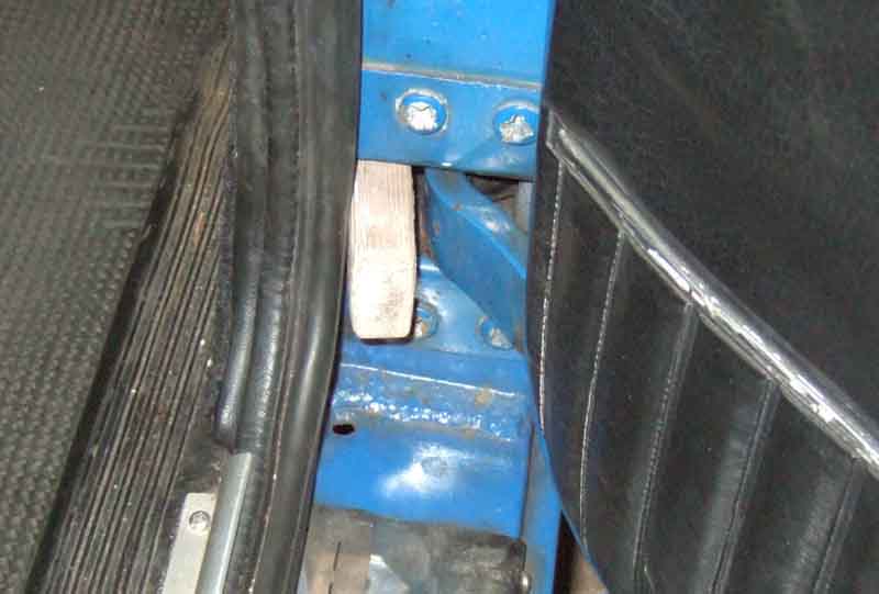 There has been some discussion of this area recently on a mailing list. John Davies nearing the end of a restoration has found that the bottom of his drivers door needs to be moved out by about 1/16" or so to clear the wing. Opinion was that the hinges can't be adjusted on the A-post, even though they have sliding threaded plates like in the door and for the striker plate. Even if the screw holes for the hinge in the A-post don't give enough adjustment I can't see any reason why they can't be filed out a bit to give more movement, but of course that would leave a mark, if not a gap in the paint, around the hinge and is why this adjustment really needs to be sorted before painting. There was talk of putting a shim in the door, but the threaded plate the hinge screws go in to is boxed in so may not be accessible. Then John described a method of bending the hinges his local garage showed him, which would achieve much the same thing without actually moving the hinge relative to the A-post. Basically you put a wedge into the hinge and close the door onto it. Pushing against the door carefully should tend to bend the part of the main hinge body that the pivot is attached to (which is much thinner than the tongue itself) and will have the effect of moving the pivot and hence the door out from the body slightly. Of course you can go too far, and it is not possible to bend it back again without removing the hinge from the body and door, or revert to Plan A and move the hinge on the A-post with all that entails. Care required!
Adjusting the height of the rear of the door relative to the front is the second-easiest of the adjustments to perform. Each hinge-to-door fixing has three Philips screws that go through the door panel, through the hinge and into a sliding threaded plate inside the door. This plate doesn't seem to be a listed part and seems to have been installed during door manufacture, and is not easily replaceable if you should strip the threads, unlike the plates in the A and B posts. If you slacken all of these you should be able to imagine being able to slide the whole door forwards and backwards on the hinges, and this sets the basic fore-and-aft position of the door in the aperture and hence the front and rear gaps. With the same screws loose if you let the door go the rear edge will drop right down, the top hinge will slide out of the door and the bottom hinge will tend to slide into the door. Likewise if you lift the rear edge of the door the top hinge will tend to slide into the door and the bottom hinge will slide out and that is how you set the height of the rear of the door relative to the front. But before you slacken the screws you need to decide whether you want the top of the vertical gap between door and front wing to get smaller or the bottom of that gap to get larger. If you want a smaller top gap you slacken the top screws fully but just slightly loosen the bottom screws. Then when you lift the rear edge of the door it will pivot about the bottom hinge and the top hinge will slide further into the door. If you want the bottom of the gap to get larger you just slightly loosen the top screws and fully slacken the bottom screws, then lifting the door will pivot it about the top hinge and the bottom hinge will slide further out of the door. However if the hinges themselves are worn or bent you there may not be enough adjustment left to raise the rear of the door to the correct position. In that case you may be able to get by with swapping top and bottom hinges over (there seems to be no difference in top and bottom hinges, only RHS and LHS) or another possibility is to shim the lower hinge to get more 'lift'. However both these will disturb the 'up and down' and 'in and out' settings of the front of the door.
With the height of front and rear and the panel gaps set there are now four more adjustments left to do - yes four. You may have to twist the whole carcass of the door in order to get the rear edge flush with the rear wing for the whole of its length. The factory used a large bar that clamped onto the top and bottom edges of the door to achieve this, Herb Adler describes the principle here.
Finally you adjust the striker plate in and out so that the rear edge of the door is flush with the rear wing and up and down so the door does not lift or drop as the lock engages, and add/remove shims between the striker plate and the B-post so that the lock opens and closes cleanly and doesn't bind. May 2016 Again the striker-plate screws go into two sliding plates that are in slots that can be accessed by removing the trim panel.
July 2019:
 A comment on a forum that amongst other problems the rear vertical edge of an owner's door was quite a bit proud. As above this is set by positioning the striker plate appropriately and a couple of us responded that this does mean that the seal is compressed by the striker plate, which perhaps might seem wrong. There is also the question of the seals themselves - whether replacements are too hard/and or too bulbous as others have reported problems here. All four of my doors (original seals) close very easily, and if only half-clicked they can be pushed fully shut without having to open and slam them. Unlike the ZS 180 which needs a good hard pull/push to close.
However if the sills and rear wing have been badly fitted, or the door skin, it will be very difficult to adjust the door to compensate - or even fit properly. For that reason you should remove the minimum of front and rear wings and door whilst fitting new sills, even though the door will be in the way. They are vital to get correct alignment.
Happy hanging.
Update September 2003: I was never happy with the fit of the drivers door which had always used the striker plate to lift the door into position slightly, which is something it shouldn't have to do. This makes a bit of a clatter when closing, and unless the lock and striker plate are kept lubricated with a smear of grease it can need a push to open and the grease can get on one's clothes. I knew this from the outset but I'm sure I originally spent ages trying to get the door-to-hinge adjustment correct so this wasn't required but was unable to do so. Finally I decided I had to try again and blow me if slackening the top hinge to door screws alone allowed me to raise the rear edge of the door into the correct position, it only taking a few minutes including removing and replacing the trim. However that moved the lock slightly forward in relation to the striker plate and the two were now binding a little. There were already three shims under the striker plate, so I used one as a pattern to make another out of even thicker plastic, and one thick and two thin have now put the striker plate in the correct position, and the door now shuts with a nice click and springs open instead of needing a push.
Keys
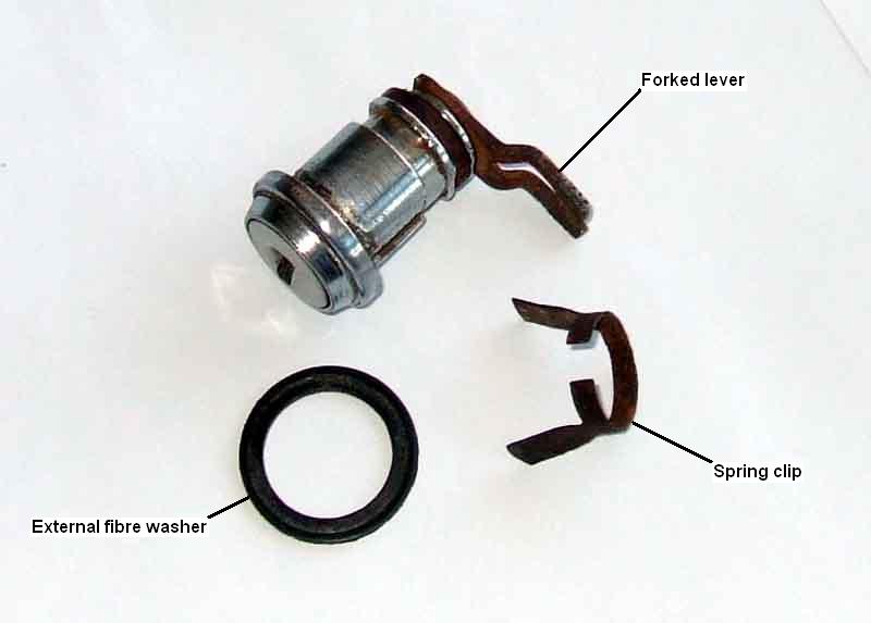 One of the first things you should consider doing, and certainly if repainting the doors or working on the locks, is to replace the very poor arrangement for holding the external lock in the door skin. This is nothing more than a flimsy spring clip which at best allows the lock to rotate in the door skin slightly, wearing away the paint around the hole and allowing rust to set in. At worst the locating 'pegs' in the door skin that stop the lock rotating too far can wear and allow the whole lock to be rotated far enough to unlock the car just with a screwdriver in the key slot.
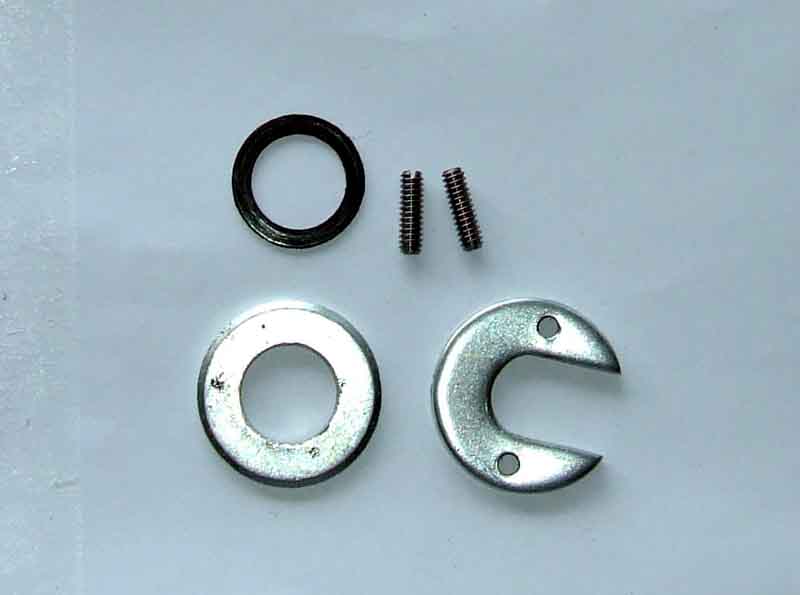 There is a much better 3rd party lock fitting kit available from many of the usual suspects which secures the lock positively in the door and giving it no chance to move and chafe the paint - MRD1067. It is quite easy to fit once you have the door trim off, you just have to remove the existing spring-clip, ease the lock out of the door slightly to be able to fit the circular washer over the end (chamfered side facing the door skin) of the forked lever that operates the locking rod sticking out of the latch assembly, relocate the forked lever over the rod, then the C-shaped washer just slides into the groove vacated by the spring-clip. Tighten the grub-screws equally, and Bob is your Mother's Brother. Note that to remove the door trim you will need to remove the door-pull/armrest, the window winder, and whatever arrangement you have for opening and locking handles, then unscrewing or carefully levering up the concealed snaps. On Mk2 cars with the rectangular safety handles simply slide the top half of the plastic finisher upwards and the bottom half downwards, being careful not to tear the vinyl. The screws in the window winders seem prone to seizing, but if you remove the waist rail as well then once you have released all the trim panel snaps you can rotate the panel downwards about the winder handle and that will give you sufficient access. Remember to refit any polythene sheets over the holes in the inner skin to protect the hardboard trim from rain-water, and if you don't have any then fit some!
August 2023: Of a number of jobs on Geoff's GT one of them is the door locks. The drivers-side had been disabled in some way with no effective wafers so anything would unlock the door. That side was bad enough trying to lever the factory retaining clip off but the passenger side was impossible. Instead of the 'legs' of the clip springing away from the sides of the lock to sit behind the panel both were stuck fast to the sides of the lock, so nowhere to get the finest point under to lever them off. In the end I had to resort to using a drift and hammer to punch the lock out from the inside. The legs were than away from the sides so must have been stuck inside the hole somehow, and here wasn't even a fibre washer against the outside face of the door. Needless to say when I knew the locks were going to be changed I said to get the after-market fitting kit as well as a pair of locks. Not knowing what came with what I also said to get a couple of fibre washers - in the event there was a pair with the locks as well as a pair with the fitting kit so he now has six!
November 2009: Cars used in all weathers and particularly those kept outside can suffer from the locks getting stiff, as can garage locks and padlocks. You can ignore it until the key snaps off in the lock, or do something quick and easy sooner rather than complicated and expensive later. Vee was kept under a car-port for a long time with the prevailing weather against the drivers side, and that lock periodically used to stiffen-up, rather than the little-used passenger side. I've seen various recommendations for oil, silicone and Teflon sprays, and graphite powder each usually stating that only they should be used! This advice from a locksmith and safe engineer says silicone and Teflon can be used, but graphite is better, and oils like WD40 should definitely not be used. I see silicone and Teflon advertised but not specifically mentioning locks, so I'd steer clear of those. Graphite powder specifically for locks is available in small quantities, but for small quantities like a lock you can make your own (as recommended on the above site). Take a graphite pencil, and cut back the wood to expose 1/2" or so of the graphite core. Fold a sheet of paper in half and cut a diagonal, so that when opened out again the crease forms a point, like an arrow or a paper dart. With the pencil held over the crease scrape down the exposed graphite with a sharp blade held at right-angles to the graphite until you have a little pile of powder. Fold the paper and tap the pile into the crease. There should be little shutter in the lock across the key entrance, wedge this open with a matchstick, put the tip of the crease in the folded paper into the slot, angle the paper and tap it gently so the graphite powder trickles into the lock. Don't do this in windy conditions or it will simply blow away! Remove the matchstick and use the key in and out and turning it to distribute the graphite and it should soon ease up. Normal use of the lock will distribute it further. In exposed conditions like Vee's you may need to do this once or twice per year.
Keys November 2010:
Replacement keys can be tricky. Using blanks and worn keys as a template is very iffy, I had a spare ignition key cut from the only key that came with the car which was itself a copy, which tended to jam in the lock. Subsequently the 'original' key started jamming as well, so I replaced the lock. Both lock and ignition key numbers should be on the Heritage Certificate so potentially available for purchase 'new' rather than recut, but needs the original locks to be on the car of course. Easy to check with door etc. locks as the number was stamped on original keys (unless you already have a recut), but not the ignition key. A spare door key seems to have been attached to the car - the firewall in the engine compartment, inner wing, and inside the glovebox have all been mentioned. Blanks are available from the likes of Triple-C (USA and Canada) but in all cases it is the pattern of length-wise grooves that is most important. Triple-C don't give these - you have to know the blank pattern number - but Moss US (but seemingly not Moss Europe) and LBCarCo show these patterns for ignition keys at least. The latter indicates which years have which pattern, but compare to your existing key before purchase and cutting. March 2019: Moss Europe have FS door keys.
 Pull-handle prior to April 65 then push-button (and hence all GTs), my experience is only with the later type. The earlier are only attached to the door at the pivoting end with two screws inside the door, with a rubber buffer in the door skin at the pointy end of the handle. The later types are secured at each end with nuts and spring-washers on studs, with fibre gaskets (617403 and 617402) between the handle and the door to protect the paint. Equivalent washers aren't listed for the earlier handles.
 The later handle push-button operates a rod with an adjustment screw in the end bearing on the latch lever, to open the door. A drop of oil or smear of grease on the rod at each end where it passes through the handle casting will keep it free.
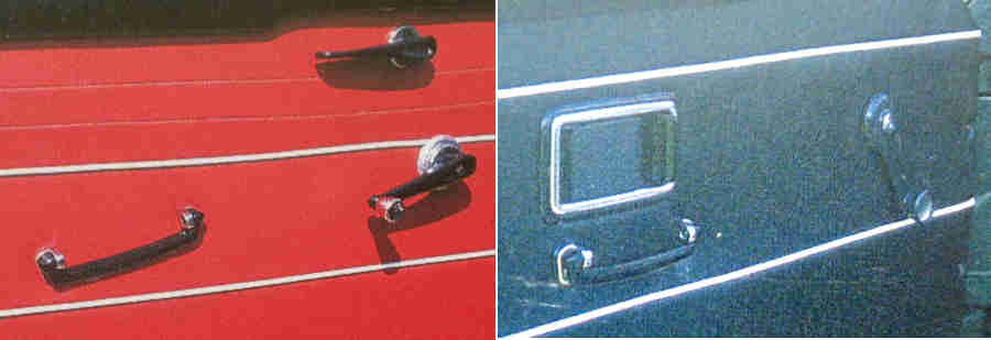 From April 1965 'anti-burst' locks were fitted, and although the part numbers for the latches differ between the later Mk1 and Mk2 the parts involved with opening and locking/unlocking seem to be much the same. The internal handle on the Mk1 uses a bar for both functions - the internal handle being moved down to open and up to lock, whereas the Mk2 uses two rods from two handles inside the car, one for opening and the other for locking/unlocking. Mk1 cars had surface-mounted handles and Mk2 had safety recessed handles. What follows relates to the Mk2.
 The 'opener' rod pivots a lever on the latch to release it, and the 'locking' rod slides another lever to prevent or allow the external button to open the door. Another rod on the latch engages with the key lock to lock and unlock the door from the outside.
I noticed Bee's driver's door button was suddenly stiffer than usual, and as it seemed to be getting stiffer thought I had better have a look as I didn't want it to suddenly fail altogether (remember Nory's wisdom: "Listen to your car, it is talking to you."). I hadn't lubricated it in 20 years, although with the door open, even with the latch pushed into the closed position with a screwdriver, it was very light to operate. So I removed the latch (remove the trim panel, but just the shoulder rail and pulling the trailing edge of the door card back should be enough to disconnect the two internal handle rods from the latch levers). The old oil was pretty sticky, but everything seemed to be moving well enough. Nevertheless I cleaned all the old gunk off and put new oil on, and the levers did seem to be a little easier. However back on the door (grease the plate the button bears on, and peer down through the window slot to engage the latch bar in the forked lever of the key lock) the button was just as stiff. Just as an experiment I eased the striker plate forward about 1/8", which did seem to help a bit. It subsequently struck me that the button in the handle may need lubrication as well. That can be accessed from above just by removing the shoulder rail with the window wound down, and pressing the button in then putting a bit of copper grease on the exposed pin has also made it a bit easier. Time will tell if that is enough. September 2010: A couple of weeks later I suddenly realised I wasn't noticing stiffness any more, and when deliberately trying it found it really easy, so perhaps the grease has worked its way into where it was needed.
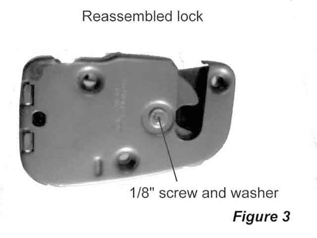 In the meantime, literally a couple of days after my initial investigation, Herb Adler writes to me from Oz having had exactly the same problem, although more severe as his was so stiff that he had broken the internal handle. However he cured his problems by dismantling, cleaning and lubricating the latch, which he describes here. He also describes installing central locking part 1, and part 2.
October 2021:
 Vee's driver's door latch breaks. Return from shopping, get out and unload, get back in and put the car in the garage ... and I can't get out! Have to open the window and operate the external button.
Door Pulls May 2011
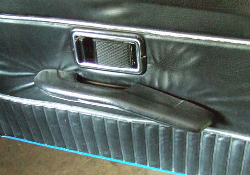 Early cars had a simple handle - Mk1 at an angle and Mk2 horizontal under the new internal door lock control, and from 1973 a combined pull and 'arm rest'. But despite having a thick wodge of hard foam around it the latter is more for safety than comfort and in the roadster does get quite uncomfortable on long runs. However my V8 has a different design extended further backwards and angled slightly downwards, and is much more comfortable. I'd always assumed it was original as there is no sign of extra holes in the handles, door panels or cards, but in response to a question about the lack of comfort I checked a number of catalogues looking for mine and couldn't find them. I then looked in my original 75 model year GT and V8 brochure to see the shorter ones depicted and not the long ones, so it is looking like a PO swapped them for something from another BL model, probably for reasons of comfort. Anyone know where they might be from?
June 2019:
 They attach to the door using screws, until 1973 the plain handles had self-tappers going straight into the door skin through the card, with the combined door pull and arm rest there are nylon 'nuts' pushed into the door skin and fatter self-tappers that screw up at an angle through the pull into the nuts. This must mean that prior to 1973 there was just a small plain hole in the skin as there is not an equivalent nut shown in the catalogues, the plastic nuts needs a larger specially-shaped aperture as shown. However the different handles seem to have had different fixing centres as well. One day while trying to close Vee's door from half to fully shut while in motion just by pulling on the handle rather than opening and closing the door I managed to pull the rear screw out of its nut stripping it. So when ordering something else I ordered four GHF1027 (originally 13H2494), two to fit and two for spares for one or other of the cars as and when.
Door Cards March 2021:
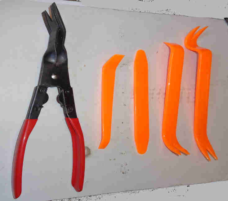 I bought the orange set some time ago but the pliers type are far more effective.
 Someone without his car available, or the doors, or the seats I can't remember which, asked for some info about positioning of the cards using the seats as a reference. He was talking in terms of making new cards and using the size of the door as a guide, but didn't mention the fact they do not go right up to the edge. I'm pretty sure Vee's cards are original, and whilst there is a sliver of painted door visible down the front edge of the passenger door, at the rear the seal just catches the edge of the card. So on that basis the cards are probably meant to be a neat fit between the seals, although as there is no scope (with the later trim clips) for positioning the card on the door, where the card ends up in relation to the seals is probably down to door adjustment, and shut-lines almost certainly trump anything else.
November 2014: Just a fitting tip really. From 1970 on the door cards or liners had plastic clips that fit in cut-outs in the back of the liners, and are simply pushed into holes in the door frame. Before that they are attached with a series of screws and cup washers, which are OK for refitting originals, but it seems that replacement liners from some sources at least have no holes. So they have to be drilled, but have to be to the centres of the holes in the doors. You could make careful measurements, but that's not feasible for my blind pal Terry. I suggested he screw self-tappers in from the back of the door frame so the points were sticking out, then using the window winder to locate the card, and feeling round the edges for equal gap, thump the liner over each screw to leave an indentation, which he could use to drill to. That worked well, and only a thump from the palm of his hand was needed. But there were some positions he couldn't get a screw in from the back. For those he cut the head off, and screwed the stump of the shank in from the outside - brilliant!
January 2024: Another couple of tips - when fitting cards to doors with the later safety internal handles make sure the rectangular aperture in the card is fitted over the handle frame before pushing the plastic clips into the holes in the doors, or you can get an edge of the card stuck on the outside of the frame and have to pop the clips out again. Also check the alignment of the hole to the handle frame using a couple of fasteners where their tips in the door hole as guides - that they are more or less central to the hole. If they are biased to oe side or the other then the U-shaped plastic trim pieces may 'fall' into the gap between the handle surround and the edge of the hole rather sitting on top of the card. The handle surround can be slid back and fore relative to the door, that may need the threaded fittings at the latch end of the rods to be adjusted.
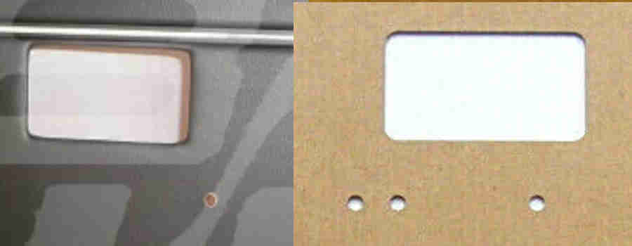 Note that some supplier photos only show one handle hole on the front and others show three holes on the back. This is probably because the different handles have different fixing screw centres, use the handles you are going to fit to determine where the other one should be. This can apply to both screwed and clipped cards, and the change from screwed to clipped was for the 1970 model year. When the cards get old and soft, and especially if damp, the clips can pull straight out of the cards ripping them unless a trim-removal tool is used that fits closely round the shank of the clip.
Door Seals February 2019
Quarter-light seals
A common complaint with replacement seals seems to be that they are too fat and/or stiff and the only way to get the latch fully closed is when the door protrudes a bit i.e. is not flush with the rear wing. Mine are very soft and pliable in comparison with replacement seal, which start making the door harder to close when it is still ajar by several inches. If anything mine are not fat or stiff enough, on both cars if the doors are closed to the first latch click then can then be fully closed with just a push quite easily. On Bee when we have spent some time touring country lanes on organised runs the doors can start to rattle up and down a bit over rough surfaces. I've 'adjusted' the striker plate to pinch the latch between the bottom flange and the pin, just short of binding, but it still happens a bit. Possibly made worse by wear in the latch and striker plate, but I'm not going to risk (very expensive) modern replacements given the quality of stuff these days.
September 2023:
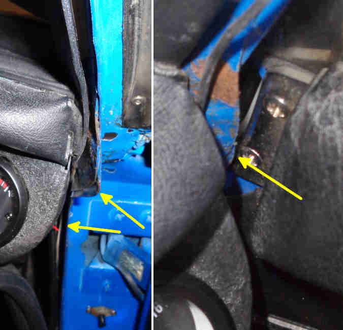 Helping Geoff to get his 78 GT back on the road I had noticed that both doors had to be pushed firmly from about six inches short of latching just to get the latch anywhere near the striker-plate, and had to be slammed to close, and when releasing the latch the door would spring out about a foot! After fitting the door cards it wouldn't close at all. My first thought was that the seals were closing onto the cards, and they may have to be moved or trimmed to fit flush with the seals rather than overlapping. But looking at the seal flange beside the dashboard it bulges towards the door at that point to meet up the the quarter-light, and the seal was being crushed so hard that it had torn where it was closest. The door was aligned with the wing so that wasn't the problem, so the flange will have to be 'adjusted'. Couldn't get grips in to bend it away from the door as the dashboard was in the way, so had to resort to a hammer and drift with the door only half open/closed to give the best access. A multiple-thickness flange at that point it took several firm whacks to dress it in. Another point being contacted too closely was at the top of the quarter-light, and excessive pressure on that can cause the Crack of Doom. First step was to look at the adjustment of the bottom of the long quarter-light leg, and it was pushed out as far as it would go i.e. pushing the top of the Q/L into the seal. I couldn't move that very far as the screw attaching the bracket to the door was too long, so that had to be removed and cut down, then the Q/L leg positioned fully towards the middle of the car pushing the top out. Still more pressure on the seal than I would like, so got some grips on the flange and bent it in a little. Now the door closes more easily with the card on than it did before with it off.
 A number of posts recently from people having problems preventing water ingress on GTs, particularly around the raised drop-glass. Quarter-light adjustment is a factor here, slots at the bottom of the long leg and the rear channel allow the QL and drop-glass to be moved in and out to some extent, however people are saying that they still have a gap. Another possibility is tapping the flange the seal clips onto out a bit, but that's bit crude, and could cause the paint to crack and start rusting. Replacement seals are often mentioned, and it seems these have a smooth rubber surface to the face that should contact the glass, whereas the originals have a raised rib (as in the attached thumbnail) the full length of the seal. With replacement seals there is also the distinct possibility that that are a stock item from one of the seal specialists and not even the rubber tube is to the same dimensions. Things like this, and the general poor quality of replacement parts from the usual suppliers, is why these days I only replace stuff if I have to. I replaced all the trim (bar the door seals) when I repainted the roadster 30 years ago, but for the GT in 2017 I only replaced the heater intake as the original showed some corrosion, and even that has a different curvature so I had to use some of the original spire-clips rather than the plastic sockets that I had intended to use.
 Another question has been whether to use the GT seals with the bonded upper-rear corner as the main suppliers seem to have, or use seal cut from a continuous strip which some of the smaller suppliers have. Vee's came with the car and could well be original, are not bonded, but that join has never rain in.
May 2022:
 Gary Robert's wrote to me about gaps between the door and the seal particularly at the lower front corners, Bee and Vee are like that but to different degrees. The original intention may have been for the door to just close onto the seal, and the door card to exactly fill the space between the upright parts of the seal so no paint is visible internally. But with replacement wings front and rear, door or skins, seals and door cards almost certainly being more common than not these days things probably don't fit as well as they should - if they ever did. In theory one could position the door on the hinges to achieve it but the external shut lines are surely more important. To get the door right wrt the seals one could position the wings for example to suit, but that is a big job and has implications elsewhere on the car, which leaves modifying the flanges the seal sits on.
Drop-glass and Regulators August and October 2017
Adjustments
Lower stop
Seals
Stiff to wind
Jumping out of the channels
Channel brackets
Handles and Screws
Dating the glass
 There were three types of regulator used over the years, but roadster and GTs of the same era always used the same one. Pull-handle roadsters (there were no pull-hand GTs) used a unique regulator, the remainder of Mk1 roadsters and GTs used another, and Mk2 and later roadsters and GTs used the third type - all different for RH and LH of course
A handy video from Graham Moore of a regulator on a board and powered by a motor, which shows how everything moves as the window is raised and lowered:
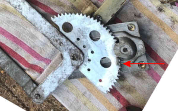 Robin Guojah is having problems getting the windows to go all the way up on a pull-handle rebuild with a mish-mash of parts. He says there seems to be some kind of physical stop in the mechanism (the stop-bolt is not fitted) and he has one (or two) bent teeth which may be causing the problem. These bent teeth seem fairly common, although I can't see them in Graham's video, and in any case where they do exist on Mk2 regulators they are at the other end of the large gear, i.e. the lowered end, as arrowed here.
Removal: A bit of manipulation is needed to get the regulator in and out of the door, and connected to and disconnected from the glass. All the following applies to later regulators, i.e. Mk2 on, but the Mk1 probably isn't much different. Originally written with more description than pictures in August when fitting-out Vee, John Maguire from Australia sent me his version in October which consists of a number of captioned pictures and a video. What's more, with a genius bit of lateral thinking he has come up with a method that pulls the glass and top of the regulator out of the top of the door, so the glass can be slid straight off the rollers of the regulator. This results in drop-glass removal being accomplished in about 15 minutes, and refitting in not much more, so I've replaced my method with his. Drop-glasses were always curved, and handed.
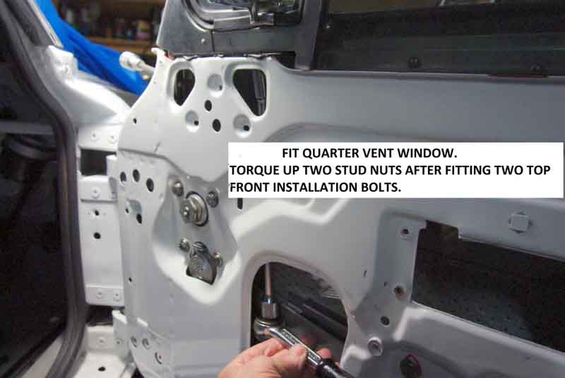 The vent/quarter-light frame can be removed with the glass still in place ...
 ... or the glass can be removed with the quarter-light in place, depending on which component(s) you need to get at.
Reinstallation
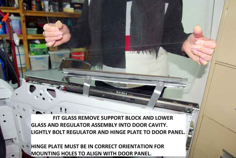 Largely the reverse of removal.
Channel brackets:
Confusing! In more ways than one. The first confusion is just how many different brackets there were originally. The Parts Catalogue lists HZA226 (RH) and HZA227 (LH) originally, with quantity shown as '2/1' for both. Then it lists HZA2066 (RH) and HZA2067 (LH) for GTs, with a quantity of 1 each, so as well as being handed side to side, GTs are handed front to back as well, although for roadsters it looks like front and rear are the same. The Catalogue doesn't indicate whether the GT items go at the front or the rear, but the implication is with the different quarter-light assembly it will be the front, and several online catalogues confirm that. This leads to the second confusion, in that unless you keep each bracket with its channel - especially for GTs - the subtle differences in shape and which way round and up they go as well as in which position will keep you occupied for hours.
Then from chassis number 146104 i.e. July 68 four different brackets are listed with HZA678 (RH) and HZA679 (LH) with two per side for roadsters and one for GTs, with HZA2086 (RH) and HZA2087 (LH) additionally for the GT fronts, so eight different types altogether.
Then Brown & Gammons confuse things still further by saying that both HZA226 and HZA678 for example i.e. the early and late universal brackets have been superseded by HZA2086, which is the later GT RH front bracket. And out of 18 entries covering all eight part numbers all refer to HZA2086 and HZA2087. The implication of that is that the GT front brackets can be used both front and rear, roadster and GT. However the descriptions say 'Single screw fitting GT & V8', which conversely implies that they are only for the GT fronts! Not cheap at £18 for a bare bracket, when Ashley Hinton are showing a pair of HZA678 and HZA679 with fittings for £19.
Ashley Hinton also refer to them as MB70R and MB70L, and Googling those numbers comes up with this Moss page which clarifies everything by just listing those two items and saying "These brackets are now manufactured with multiple fixing holes to suit front quarter light channel and rear channel fixing." so should be correct for both roadster and GT, front and rear. Even more expensive at £20 each for a single bare bracket. Motaclan/Leacy have them at £16, but it would be worth checking with Ashley Hinton as to whether their MB70s can be used both front and rear in GTs.
Adjustments:
 The bottom of the 1/4-light long leg can be adjusted but it's primary purpose is to get the correct alignment of the quarter-light to the windscreen upright. The top of the channel at the lock end of the door and also one of the two possible adjustments at the bottom should lightly hold the glass to stop the glass jumping out as it is wound up and down. Pressing too hard on the edge of the glass will make it stiff to wind up and down, but too much slack on the GT will allow the glass to touch the B-post trim.
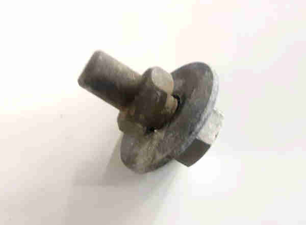 There is a stop-peg near the top of the inner skin by the regulator handle so that wound fully up the top of the glass just tucks neatly into the rubber piece at the top of the 1/4-light frame.
Lower stop:
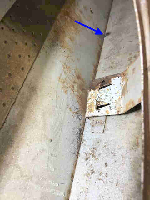 This is a bracket in the bottom of the door AHH7550 (RH) and AHH7551 (LH) on which sits a felt pad AHH6434. Note that in September 2023 Moss Europe show two pads on the item page but only supply one unless you specify a quantity of 2. The Parts Catalogue indicates they are held in place with screws and spire nuts, but neither my 73 roadster nor my 75 V8 have screw heads on the bottom of the door or the inner skin, i.e. they are welded in place. The 77 and later Parts Catalogue does not list those screws and nuts, so I presume at some point they were welded in, maybe before 1973, or at least before the doors that came with both my cars were made! They seem to be stainless now - certainly not for appearance, but maybe to prevent them rotting-out as the originals have done. However if the remainder of the door is still painted mild-steel that's still going to rust. At the time of writing I've seen an eBay source for these at £29 plus £5 P&P - which made me choke. Motaclan/Leacy for example has them at £23 plus P&P, and if buying with other parts the P&P for that item will be marginal.
Seals: August 2020
 Inner 'furry' seals are stapled to the vinyl-covered waist rail. On the roadster outer rubber 'scraper' seals are pop-riveted to the door skin directly, and on the GT they are clipped to the bright finishers (AHH7476/7) which are pop-riveted to the door skin. To access either the drop-glass has to be removed, and on the GT because the outer rubber seal is clipped to the door finisher it may be necessary to remove that from the door which will need the GT quarter-light to be removed as well.
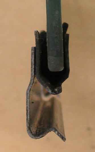 There is also a glazing seal at the bottom of the drop-glass to the channel that is raised and lowered by the regulator - 37H4297 (78447A from Rimmers), which is a flat strip the same as for the quarter-light vent glass. This has to be folded into a U-shape, which some have said is extremely difficult, but it can't be as difficult as when the same strip is used for the 1/4-light vent that has to go round two corners as well! But researching this seal I came across this U-channel seal AHA7486M for the 1/4-light vent glass (but you still have the problem of getting that to go round the corners) shown as an alternative to the flat strip for the drop-glass. In theory both should be easier for the straight drop-glass channel than the vent glass, and the vent glasses weren't that difficult on the two sets I have done.
Stiffness when winding seems to be the biggest problem, so much so that people break the plastic handles and replace them with after-market metal ones. With several BL vehicles over many years I've never had this problem, but as I say many complain of it. The glass slides up and down in 'flocked' rubber inserts fitted into the metal channels of the 1/4-light frame and another plain channel at the lock-end of the door. These rubber strips can rip and cause the glass to jam, and if the flock wears off the rubber may well make the action a lot stickier. The two channels may also not be in line so are trying to flex the glass as it moves up and down, and the regulator mechanism may also be stiff from rusting or lack of lubrication. The first thing to do is to determine whether it is the regulator or the glass that is causing the problem.
There is quite a bit of lost motion in the regulator and this can be used for diagnosis. Wind the window down, then start winding it up. Now grasp the top edge of the glass and lift - it should come up at least an inch or so. Now turn the winder again in the 'up' direction. It should move easily for an eighth of a turn or so before it starts trying to raise the glass some more, then you know the problem is with the glass and the channels, and it was probably very stiff when you tried to pull it up by hand. But if the glass moves relatively easily when pulling it up by hand but the winder remained stiff while taking up the lost motion, then you know the regulator is the problem. In theory if the glass gets easier to move as it is wound up that could well point to the lock-end channel being the problem, as there is progressively less of that in contact with the glass as it rises. But note that the regulator should move very easily back and fore through its lost-motion area, this can be checked in various places between fully up and fully down, but pulling up the glass by hand will always exhibit a certain amount of resistance. Of course you could have both problems! In which case deal with the regulator first, then you will know how much of a problem the glass is. There are quite a few pivots, gears, wheels, and a large spring in the mechanism, any one or more could be seized or stiff, so you will have to work through them all. If the car is a daily driver and is regularly going to get wet use waterproof (white) grease to avoid rain running down through the doors washing it off. For 'dry' cars a general purpose grease should be fine.
I've seen silicone lubricant spray recommended for easing the glass channels, but what long-term effect it has on the rubber, and whether any short-term benefits are then replaced by a worse long-term situation I don't know. Much better is a suggestion from Mark Robinson to use graphite powder, put some on your finger-tips and you can feel how slippy it is, but it never attracts dirt or gets sticky, which is why it is used for lubricating locks. Making your own like for door locks probably isn't feasible in this case due to the quantity that will probably be required, Googling 'graphite powder' came back with several sources at under a fiver a bottle. However the point is that like metal winder handles, it shouldn't really be necessary, and it is better to fix the root cause once and for all rather than bodge it and have the problem arise again later, and adjusting the rear channel may be the answer. Examine the condition of the rubber inserts and if in any doubt as to their condition, replace them. Physical wear and tearing of these can be caused by incorrect adjustment of the lock-end channel or buckling or crimping of either channel so this should be checked before using new inserts. It's possible new non-OE rubber inserts are too fat or too sticky, which leaves you with a bit of a problem. It will be possible to open out the lock-end channel a little which should at least halve the problem, more care will be needed for the 1/4-light frame, especially the upper half.
October 2022: Someone on the MGOC forum is complaining that his drop-glass is stiff because the regulator is imparting a side-ways thrust to the channel clamped to the bottom of the glass, which is forcing the glass into one or other channel as it is wound up and down. There are two buttons or bobbins on the lifting/lowering bar of the regulator that sit in the drop-glass channel and this video from Graham Moore shows that they have to slide several inches back and fore in the channel as the glass is raised and lowered, so they and the channel need to be free-moving and well lubricated, with waterproof grease if your car regularly gets wet. Excessive sideways thrust on this posters car must be coming from a stiffness there, that shouldn't be there. Either there is a lack of lubrication or perhaps the channel is distorted and is binding on the buttons/bobbins or the lifting bar.
June 2019: Since reassembling Vee after her repaint in 2017 I'd been conscious that the drivers side was a bit stiff ... then the handle broke. Really quite stiff pulling up and pushing down, so door card etc. off and I was able to move the rear channel back about 1/8" top and bottom, and now it is really easy. Don't fancy the chrome and especially the alloy replacements, so go for standard. Some sources recommend an original at about £5 and a copy for about half that, others only offer the cheap one but don't say that it is a copy. For that money it's not worth messing about with a copy, and I get a pair in case the design has changed (which it hadn't ...). Subsequently I felt that perhaps it was too loose, and a slight rattle made me wonder if the edge of the glass was chafing the B-post trim-strip while under way, so I moved the channel back in a bit. That gave me the opportunity to replace the two door-pull nylon nuts in that door as the screw pulls out of the rear one if I pull on it too hard.
As well as being buckled and having the wrong brackets it's fitted with metric-head UNF screws which is irritating, and missing the stud from the bottom of the channel so using a nut and bolt instead, which was a fiddle. But at least the old channel came out the top with the glass and regulator in-situ, the new one with the stud at right-angles to the bracket won't go in that way. But winding the glass up it can be fiddled in through one of the door apertures and fed up - at least it can within the inner flexible channel fitted, it remains to be seen whether it can be with that fitted, or whether the glass will have to come out again.
Handles and Screws:
 Mk1 regulators HZA2118 and HZA2119 with the hex spindle for the handle 34G2528 use fibre washer ADA5669 between it and chrome escutcheon AHH6336 against the door panel, and fixing screw ADH834. The escutcheon has two spikes which look like are pressed into the door card when the handle is screwed to the regulator, so the escutcheon does not turn with the handle. Shown by suppliers but not in the Leyland Parts Catalogue is sponge pad AHH6337 which almost certainly fits over the regulator spindle behind the door card to press the card against the spikes on the escutcheon. Screw is 54K205 with 10-32 UNF (3/16") x 1/2" thread. Spring washer WL700101 is also shown but will make the pan-head screw stand proud of the escutcheon. Also shown for the Mk2 but none of mine have one and have never come loose, so I don't think it's necessary.
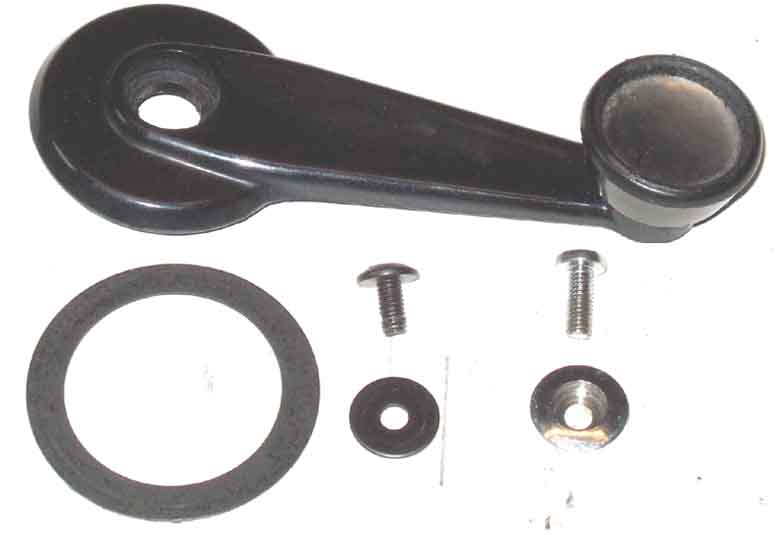 Mk2 is a lot simpler and used black plastic handle CZA7109 with fibre washer CZA2279 against the door card. The fixing screw threads are No.10 or 3/16" UNF x 1/2", originally black flanged screws CZA7194, but are now ZKC3317 which consists of a black screw with shallow domed head and separate washer. The later chrome screw is PMP308 and the escutcheon CZA2367, as shown in the 77 and later Parts Catalogue, and B&G additionally show them with a No.10 spring washer WL700101. Unlikely to have been used with the original flanged screw, and a shiny washer between the black screw and separate washer would look odd.
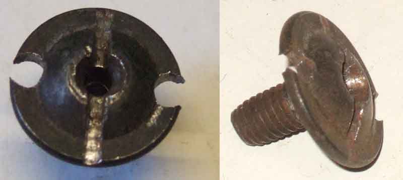 Bee originally had the flanged screws which was useful when I found one of them seized in the regulator and stripped the cross-slots. I was able to drill two holes in the flange and use a pair of stout pointed pliers in those holes to undo the it. Initially I cut a slot across the head to reuse it, but eventually replaced both with the separate black screw and washer. Vee has the later chrome screw and escutcheon, and when removing them in 2016 for the body repaint (even though they had been off several times before) the drivers handle screw had to be drilled out as again the cross-slots stripped. This meant that the regulator needed to be drilled and retapped - preferable to replacement of the whole regulator! Fortunately Vee was at a workshop with a pillar drill at the time, so I was able to drill an accurate hole through the stub of the old screw and tap to 3/16" UNF. More recently still someone was asking about longer screws - perhaps having stripped the existing thread in the regulator so had to drill and tap deeper. A Mini site quoted CMZ312 which are 3/16"UNF x 3/4" so the length is OK, but they are countersunk and yellow zinc. You would need PMP312 for chrome pan-head, or PMZ312 and paint it black.
Quarter-lights March 2013
Adjustment
Glass
Seals
Repair and Restoration
Dating the glass
The quarter-light frames were chromed brass until May 1972, changing to stainless. The vent handles were curved on Mk1 cars and straight on Mk2.
 Early roadster QLs had a relatively flimsy bracket at the front screwed to the top of the inner door skin. Later units and all GTs replaced that with a more robust short leg that goes down inside the door and secured with two bolts through the front of the door casing. Even with the more robustly attached later unit you should still avoid pushing the door open or closing it using the drop-glass or quarter-light.
 Roadster QLs sit on a short rubber gasket on top of the door, and GT QLs sit on a thin horizontal part of a vertical finisher that runs the full width of the door.
August 2021:
 A question has cropped up about the screws securing the triangular finishers at the lower front corners of the quarter-lights. The side one is behind the bright trim strip that runs across the top of the GT door (they are above the rubber strip on the roadster), and Graham Moore rebuilding his doors said they were too big and pushed the trip strip away from the finishers leaving a gap. Vee's trim strip is almost flush with the finisher, I can't get a finger-nail in the gap, although I notice that the strip does move out a bit where it encounters the edge of the finisher, but then lies flat against it (the rubber strip on the roadster is the same). My screws are self-tapper with very low-profile domed head and integral washer, and are also used on the front edge of the quarter-light. Not listed in the Leyland Parts catalogue for the GT ... although 17H2503 is shown for the roadster. Suppliers catalogues show the same screw for both roadster and GT, with Moss showing either 17H9953 or 17H2503 as alternatives although the former is a completely different countersunk screw which would never fit correctly, Brown & Gammons only show 17H9953 also countersunk. Googling 17H2503 does picture the correct screw from several sources, but may not be what you get.
Removal/refitting:
 The quarter-lights can be removed with the drop-glass still in place. When refitting it's important to tighten the three sets of nuts and studs in the correct sequence or the door frame can become distorted and the quarter-light incorrectly positioned. There are two studs that go down through the top of the door that take deep nuts, two bolts that go through the front of the door into the short front upright (except early cars), and the adjustment stud at the bottom of the long leg which is done last. The upper long nuts and the forward-facing bolts must be tightened progressively to pull the quarter-light forwards and downwards into the door frame, while the quarter-light is being pushed downwards and forwards. If the front bolts are fully tightened first the quarter-light may not be fully seated down onto the top of the door, and tilt as the stud nuts are tightened, or if the stud nuts are tightened first the quarter-light may not be fully forwards in the door casing.
Adjustment: This is vital to get right if splitting of the door skins - the Crack of Doom - is to be avoided, or even cracking of the screen (one person has described how closing his door physically moved the screen and eventually cracked the glass), and is a combination of door, screen and quarter-light positioning and how they interface with each other. There are three parts in obtaining the correct adjustment, and they need to be done in the right order. The positioning of the door and its hinges, the fore and aft positioning and tilt of the roadster screen, and the long leg of the quarter-light going down to the bottom of the door.
October 2022: A couple of people on the MGOC forum have mentioned recently that the top rear corner of the drop-glass fouls the B-post bright trim with the door shut. As well as everything else it's important to tighten the four QL to door bolts and nuts correctly otherwise the QL can end up in the wrong position. But even then it can be a function of the basic door shape and positioning especially it it has been reskinned. One possibility to correct this problem is to put a spacer on the rear QL stud where it goes though the top of the door, which will tilt the whole QL forwards slightly, being in mind that if you go too far it will then hit the underside of the gutter trim.
Glass: Roadster quarter-light glass (the opening vent, not the drop-glass) was originally flat, with a single part number for both sides, until the change to stainless frames in April 72 when they gained a slight curve. GTs always had two part numbers, so may well always have had curved glass and hence had a different part number for each side. The drop-glasses on both models were always curved, and handed.
Vent Glazing Seal
Screen Upright Seals
Vent Seal: - July 2019
 Some anguish about these on the MGOC Forum on a couple of occasions recently, unsurprisingly with replacements. The biggest problem seems to be that there is a large gap between the seal and the lower part of the vent frame which exposes the pivot. On my originals there is no apparent gap on Vee, and only a tiny gap on Bee if you really look for it. The gap between the visible parts of the fixed frame and the opening vent is about 7 to 7.5mm on both cars. The shape of the moulding is also different alongside the pivot along that lower edge. In front of the pivot the seal covers the vent frame as that part turns inwards as the vent is opened, but aft of the pivot the seal is flush with the bottom of the vent to allow it to open. On mine that transition is angled, whereas current replacements are cut off at a right-angle. And contrary to the usually held view that all suppliers get their parts from the same manufacturer, those from Rimmers and MGOC appear to be different to each other in this area. None of my seals are visually perfect by any means, but they don't let in rain and given the quality of replacement parts these days especially rubber I don't change stuff unless I have to.
Vent Glazing Seal:
 When restoring both Bee's and Terry's quarter-lights getting the vent glass into the opening frame with the seal was a challenge. The glazing seals (27H8705) are flat strip and I couldn't see how I was going to get that folded into a U-shaped channel to fit around the edge of the glass as well as go round the 90 degree or so corners. In the end I cut darts at the corners leaving just a narrow joining strip and that seem to go in fine ... then it oozed straight back out again! For Bee I left them clamped up both horizontally and vertically in a wood frame for a few days, but for Terry's I think only overnight, and they've been fine ever since.
February 2019: Since then I've read of a method that avoids cutting the darts. This involves putting the strip in hot water and stretching it lengthways, then laying it lengthways along the edge of the glass, and at the corners the sides shrink back to lie almost flat against the glass as it is pressed into the frame. Probably advisable to clamp it up as before, and to leave the trimming for a few days in case it shrinks back from the edges and leaves gaps.
 January 2021: But Richard shows that by far the bulk of the seal will be trimmed off, leaving just a relatively small amount to be squashed into the corners, and fitted his without darts or hot water. Note that the rain channel at the front lower corner lies against the glass, the glazing seal is wrapped around it.
August 2020: In an MGOC forum post Ben Columb shows a moulded glazing seal being used for the front quarter-lights, similar to that used for the rear Q/Ls. The rear channel is noticeably deeper than the front channel, and the moulded seal protrudes slightly, but doesn't protrude any more from the shallower front channel, implying it's either a different seal, or has been trimmed in advance. He says both old and new were the same and he got the new from the MGOC (or maybe Moss ...). They specify 27H8705 but Googling that just comes back with the flat strip type from anyone with pictures. September 2020: The topic has arisen again and this time I happened to rediscover a picture of a partially dismantled GT rear quarter-light vent which I think resolves the conundrum. Although the rear channel is almost twice as deep as the front channel, it's obvious that the rear seal goes nowhere near the bottom of the channel, and so it's probably that rear seal that Ben used in his front vents as he shows it prior to trimming and it is much longer than needed.
July 2022: Spotted this version of the glazing seal at Brown & Gammons which is already in a U-shape) (but not moulded like Ben's) - AHA7486M, as an alternative to the flat strip. It still has to be turned through two corners though.
Repair and Restoration: Not content with reassembling a GT 'All by Touch' a couple of years ago my blind pal Terry bought a 67 roadster in a similarly dismantled condition. This had most of the outer bodywork done and had been primed, but then had been abandoned for a long time, and underneath was in very bad condition in places. He had the body finished and painted elsewhere, but again is doing almost everything else himself. (He completed it to gain its MOT at the first attempt in June 2015, but by the end of July he had succumbed to cancer and passed away).
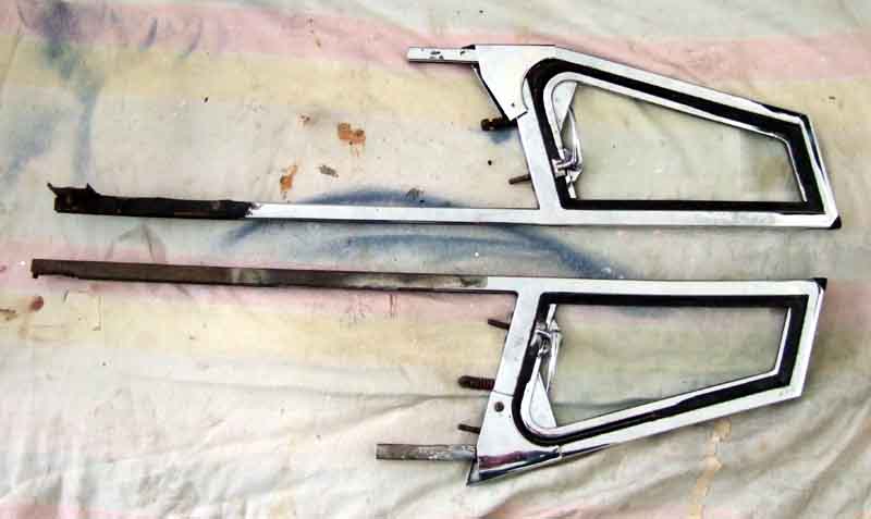 Whilst he could tell the chrome on the quarter-lights wasn't too bad he still wanted them rechromed. One has a broken top mounting stud and on the other the bottom stud plate has corroded away. Three out of the four hinge parts had broken or were missing, and a bolt had sheared-off in one of the front mount threaded plates. I found several rechromers in Birmingham and the West Midlands quite near to me, hanging on from their industrial past, and one of them will rechrome them for £70 each. They know MGB quarter-lights and do them for someone else restoring them. He wants £350 a pair for restored - exchange - with a £200 surcharge each in case your exchanged unit can't be restored! A retailer of restored units wants £250 exchange each!!
For rechroming they need to be completely dismantled, and what with that and the several repairs that needed doing it was going to be more than Terry could manage. I offered to do them for him, and he jumped at it! Terry already had the four upper stud plates and nuts which he sent up with the quarter-lights, and doing some research I found that Brown & Gammons seem to have practically everything else I might need, including small parts like the handles and pivots (expensive though!) if they can't be rechromed successfully. Fortunately the main frame, the opening vent, capping and rain channel and the glass are all in good condition, even the felt channel in the long leg. The only part that no one seems to have is the rivets to secure the rear top mounting stud and the latch plate for the handle on the opening window (but see below). The rivets for the hinge and the handle pivot on the opening vent are available, but they are smaller. As I recall the handles are held on with a roll-pin which can be driven out.
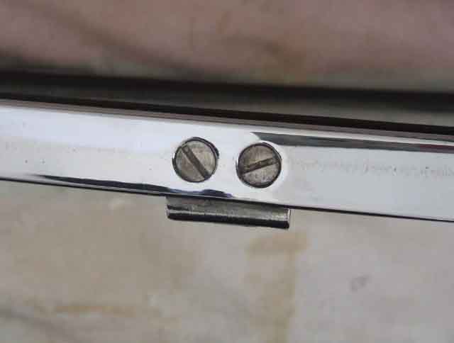 Interestingly the hinge on the main frame is held on with two countersunk slotted screws, one of only two places I'm aware of where they are used (the other being used to hold the mounting plate for the distributor in the block). However on the later stainless units both halves are riveted. One of Vee's - the vent half - was broken when some scrote got inside, but each half is available separately (gotta love these cars), and I was able to drill out the old blind-rivets to get the broken-off bit out, and fit the replacement with pop-rivets.
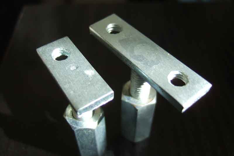 Also interestingly the replacement top stud plates have threaded holes for a screw, the same size as the hinge screws. And whilst a screw was originally used for the front stud a pop-rivet will be perfectly satisfactory, as the only thing it needs to do is hold the stud from flopping about while the quarter-light is being fitted and the nut attached to the stud. Once tightened it serves no purpose at all. However screws are no good for the rear stud as the latch plate for the handle on the opening window sits on top of it, which is why that one is riveted. The original rivets are flush both sides, but whilst pop-rivets are nearly flush at the one end, at the other there is always the crumpled tube and ball from the end of the pin sticking out, and I wondered whether there would be enough clearance for that. There is even less clearance below, just the thickness of the gasket between the quarter-light and the top of the door.
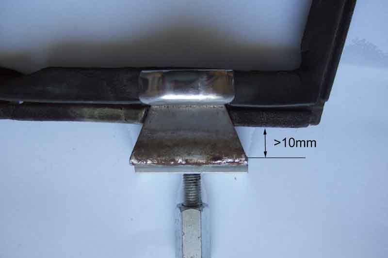 In fact there is plenty of space in the channel between the latch plate and the bottom of the seal for the vent. However I'm still wary about using pop-rivets as the handle closing the window against the latch will tend to bend it back and fore, which could well loosen it. The stud plate itself is fine as that is pulled down onto the bottom of the channel by the nut underneath. So a screw up through the frame, the stud and latch plates, with a nut on top of the latch plate, seems the way to go.
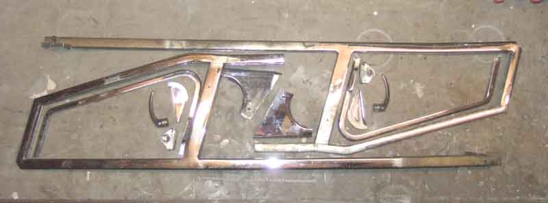 Ready to go to the chromers now, with the lower stud plate repaired, and the forward-facing threaded plate repaired. I removed that, thought gripping the remainder of the bolt that had gone through the plate with a pair of grips was worth a try, and with a bit of releasing fluid it just unscrewed. Refitted that with pop-rivets as again that is simply pulled against the channel when the deep-head bolts are tightened.
To be continued ...
May/June 2013:
 Took a while to get the parts back from the chromers - Castle Chrome at Dudley. Initially they said they would be four weeks, and to ring a couple of days beforehand. I did and they said they would be ready for 5pm on the Friday, which is no good to me at that time of day because of the traffic between Solihull and Dudley, so I'd collect them Monday lunchtime. They then said that helped them as they were a bit pushed, i.e. they hadn't started them yet. After another repeat of that I realised that each time I agreed a date it was going to be 5pm that day, so agreed a date but didn't go, then double-checked next morning that they were actually ready before setting out! All a bit casual, I was beginning to think they had lost the parts. Even more so when I did go, the goods receipt and despatch area is a large warehouse full of pallets of industrial-size and quantities of stuff for plating, and amongst them is my two frames and handful of small parts. But carefully packed and wrapped, and opening them up the results are absolutely superb, well worth the cost.
In the meantime I'd obtained a considerable number of replacement parts, so now it was a case of very careful reassembly so as not to mark the new chrome. You have to work out the correct order of doing things, like rivet the hinge into the opening part before fitting the glass and glazing seal, which involved working out the best way of closing a blind rivet without a press. One of the trickiest jobs was getting the glass and glazing seal into each frame. Despite clamping them up it just wouldn't go in as far as it should. Eventually I realised that to secure the handle brackets in the opening frame I had used pop-rivets as the correct blind rivets weren't apparently available from any of the usual sources, and the bobble on the top was sticking up too far and stopping the glass going down and hence in as far as it should. So more research, and then I find that the correct rivets (AHA7554) are available from Moss Europe, but they are only listed for some of the models and not the MGB. Earlier I had also found that some of the parts listed by another supplier are incorrect and vary from model to model, so more research was needed to find the correct ones. (December 2017: Currently available from Moss, Motaclan/Leacy, and several others.) After that the glass went in fairly easily as I'd previously replaced Bee's in 1991 and repeated that process.
 When I restored Bee's in 1991 one part that wasn't available was the brass (apparently) distance tube on the pivot under the frame, and Bee's were beyond re-use. A spring goes over the tube and a Nyloc nut and washer fitted, and this provides the friction to keep the vent in the desired position against air pressure when driving. I could have left it off and just tightened up the nut until the vent had suitable friction, but thinking "brass tube - model makers" went to a local modelling shop. One size went over the pivot nicely and another inside the spring, but both were pretty thin as far as the walls went. However the smaller of the two was a perfect fit for the inside of the other one, so that was me sorted. The tubes were about 14" long originally so I had plenty left over for Terry's (and for several more). The usual suspects do list the tubes now - but oddly a different one for roadsters (17H2518) to GTs (27H6875), and only the roadster one is currently (August 2020) available.
 I can understand the pivots being different (roadster 17H2512 for the curved handle vent and BHH717 for the flat handle, GT AHH7691 for the curved handle and BHH716 for the flat) as the vents are different heights and pivots at different angles. The springs are the same for all four (AHA7544), but the roadster pivot has a straight shank whereas the later GT is stepped which could require a larger diameter tube. However the earlier GT item is straight like the roadster so why the difference in tubes? Unless the tubes are a slightly different length (shorter on the GT so the spring applies more tension to keep the larger vent open against external air pressure? The QL on both roadster and GT sits on top of the door, the bright trim strip of the GT sits alongside the QL, so the assembled pivot, tube, spring, nut and washers just go through a hole in the top of the door when the QL is fitted so length is not an issue there.
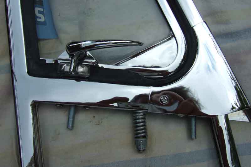 One of the most annoying things was the poor fit of the replacement hinges from Brown & Gammons. They attach to the frames OK but are dimensionally incorrect, mate together very poorly, and position the opening vent too close to the back of the channel for the drop-glass so the edge of the glass and the corners of the frame foul the seal. Others have said that Moss males don't fit their females. I'd previously spoken to someone else who restores these, and they said if they have to replace the hinges they don't guarantee the fit afterwards, and I can see why! I spent more time getting these to fit decently than anything else, which involved some careful 'machining' to improve the fit by over-drilling the inside of the hole while leaving the entry the same size. (December 2017: Michael Nunn on the MGOC forum said he got his from MGOC about May 2014 and had no problems. January 2018: Jim McCrae said MGOC had told him they get theirs from the same place as Moss, bought some from B&G and they were fine! So the upshot seems to be to keep buying from different sources until you get two halves that fit together and position the vent correctly!!) I got one working nicely, but the other was still binding, which I eventually discovered was because the main channel was bowed in towards the vent instead of being flat. I'd not noticed that before, as all the hinges had been broken so I couldn't see the fit before I started. I didn't fancy trying the straighten the newly chromed frame, so settled for relieving the seal instead and that is now much better. Still not perfect, but I don't see how I can improve it any more. So then it is a case of parcelling them up with copious bubble-wrap between two sheets of hardboard, hoping that they don't get bent. I'll have to insure them for at least £750, as that is the cost of replacing them if they get damaged beyond repair.
Sill Threshold Plates July 2019
 I'm not usually one for blingy trim but I made an exception for sill threshold plates. A nice finisher to the door opening and they do prevent the top of the painted sill from getting scuffed, stainless with a number of logos and patterns available from the usual suspects. Bee came without any so I added some after the paint job. Normally secured to the sill by stainless round-head screws, drilling the hole for the front lower screws either needs the doors to be off or a low-profile right-angle drill so I left that one out. There is also the question of whether drilling holes will introduce a rust point, and John Maguire in Oz opted to use self-adhesive magnetic strip to attach his. Vee came with threshold plates and on removing them for inspection I did find some rust underneath, but treated and Waxoyled and it didn't get any worse - which is what I did to Bee's from the outset, working it into the screw-holes. John had a different problem in that the flange on the plate was too deep for his sill step so he had to cut that down to 8mm, which put it right through the screw holes. I don't know why that should be, both Bee and Vee have about 16mm to the step, the same as the threshold plates, and whilst the edge does go right to the bottom the top surface is flush with the sill. It may have been a side-effect of Australian-produced body panels. I know the shells were assembled there, and also that at one point they modified the doors for close shut-lines but found that when the car was on its wheels they couldn't get the doors open! Lots of info on Australian cars here.


