Gearbox Switches
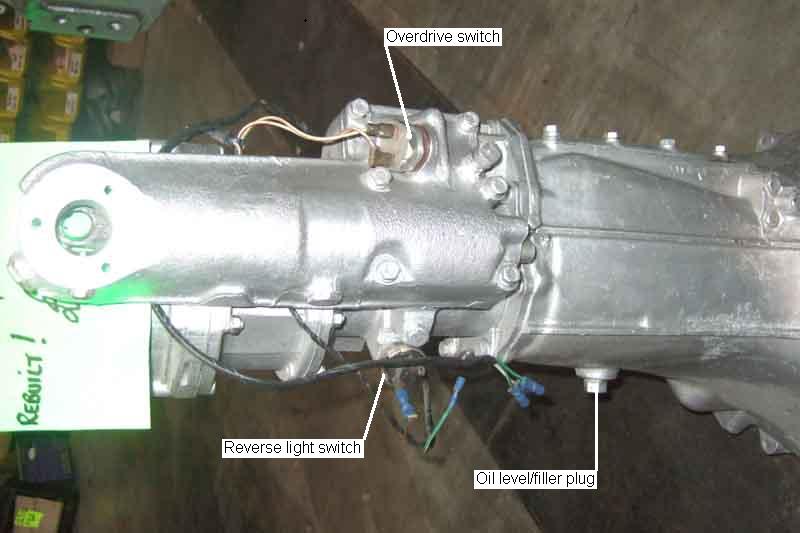
Location of the reverse light and OD switches on a later 3-synch gearbox, at the front of the gear lever and remote control housing:
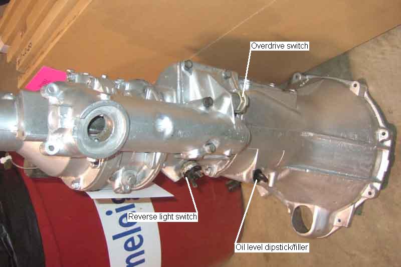
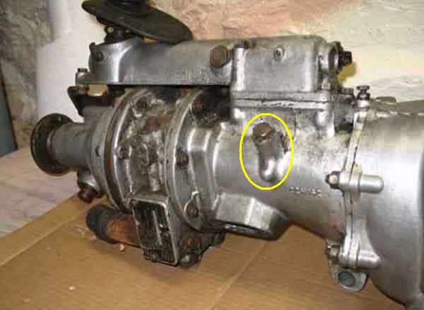
The 4-synch (in this case a UK rubber-bumper with the side filler/level plug, chrome bumper had the same dipstick as 3-synch) gearbox is similar to the later 3-synch with OD, although the OD switch faces the other way:
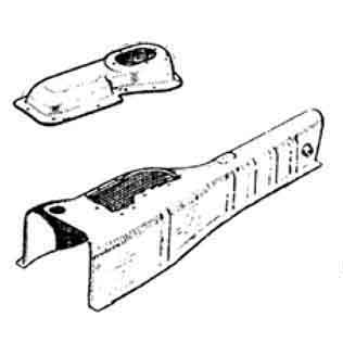
Showing the large access panel on top of the 3-sync tunnel (left), this should be enough to get at both the OD and reverse light switches: Image from Moss Europe
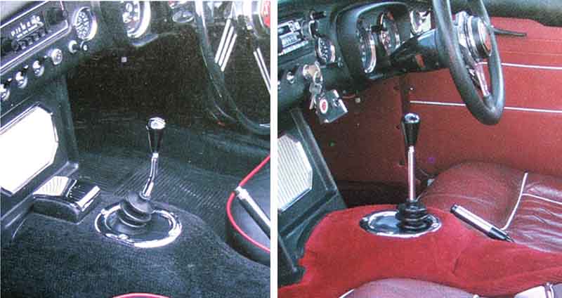
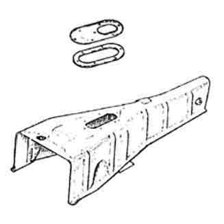
The Mk1 tunnel has a pronounced hump round the gear lever, with the non-OD having a cranked lever positioned towards the front of the tunnel cutout (left), and the Mk1 OD a straight lever positioned towards the rear. Both levers have a hidden kink under the rubber gaiter: (Clausager)
Showing the smaller access panel on the Mk2 4-sync, the rear crossmember and back of the gearbox has to be dropped as well although care needs to be taken not to damage the speedo cable: (Moss Europe)
Incidentally this shows the 4-synch removable panel (HZA1431) correctly with the hole for the gear lever towards the rear, it is shown the wrong way round by Moss and in the Leyland Parts catalogue. Replacement tunnels do not seem to come with the fibre-board ring that the gaiter screws down onto, instead gasket AHC188 is shown for under the panel by various suppliers but the Leyland Parts catalogue only shows this under the auto selector unit. However a pal's 78 has the panel with the fibre-board ring on top and the gasket underneath.
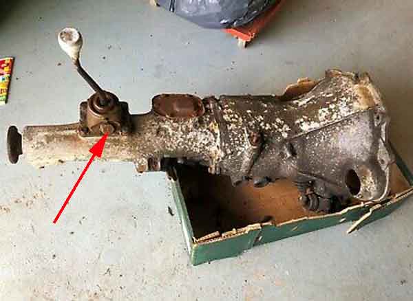
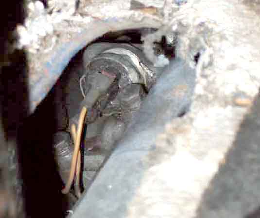
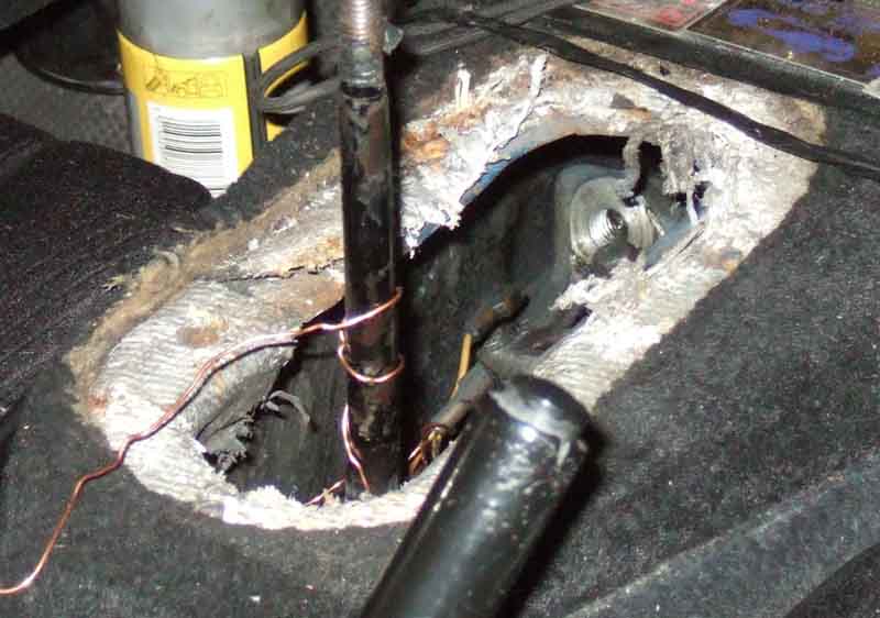
Access hole cut by Trevor Harvey when he couldn't remove the switch from above. He made a cut on three side and bent it down, intending to fold it up and weld it back, but I suggested a slightly larger panel secured with sealant and self-tappers would be preferable:
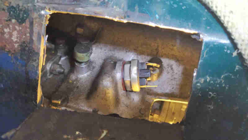
Incidentally the gearbox breather is shown ahead of (left here) of the switch.
The lever is in the same position on 4-synch both OD and non-OD: (Clausager)
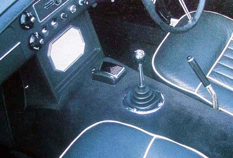
 Chrome-bumper cars (both 3-synch and 4-synch) have the dipstick for gearbox oil level accessed from under a rubber plug on top of the tunnel behind the centre speaker/console panel, rubber-bumper cars have the side level/filler plug. 77 and later models have the same switch arrangement as earlier 4-synch, but different wiring to cater for the gear lever-mounted manual OD switch.
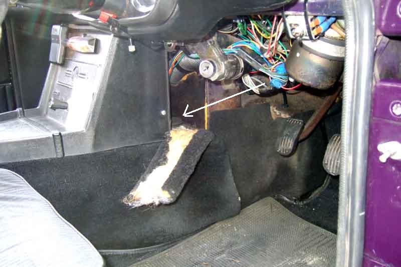
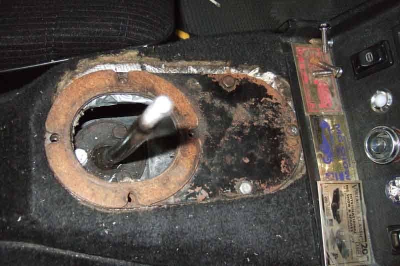
Accessing the 4-synch OD switch is really tricky. But by removing the small panel on top of the tunnel, removing the bolts from the removable cross-member and lowering the tail of the gearbox as far as it will go, and levering the gearbox towards the right (it may be advisable to disconnect the speedo cable to avoid damage), I can get my hand in. If you have a 72 and later car with the centre arm-rest and cubby, cut the carpet around this access panel as well as round the gear lever hole, which means you don't have to pull the tunnel carpet back to remove the panel:
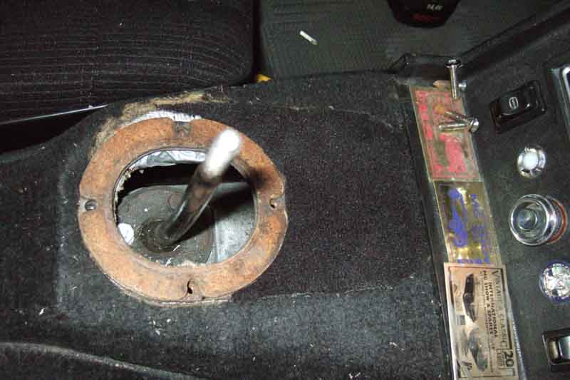
The panel should be secured by three Setscrew Pan Head Pozi 1/4 UNF x 1/2" SE604041 and spring washers - only one here plus two random hex screws. On a pal's 78 one of these came out just fine but the other three were seized. Tried using an impact screwdriver, it started to turn, but eventually I just bashed the nut off from under the tunnel and had to fabricate a repair piece from a strip of metal with a low-profile nut inset and welded, pop-riveted to the underside of the tunnel. On that car there is very little clearance between gearbox and tunnel, not even enough to get a finger in, there is more on Bee and Vee.
Keep the section of carpet from over the panel, and drop it back in place for noise reduction before re-fitting the arm-rest:
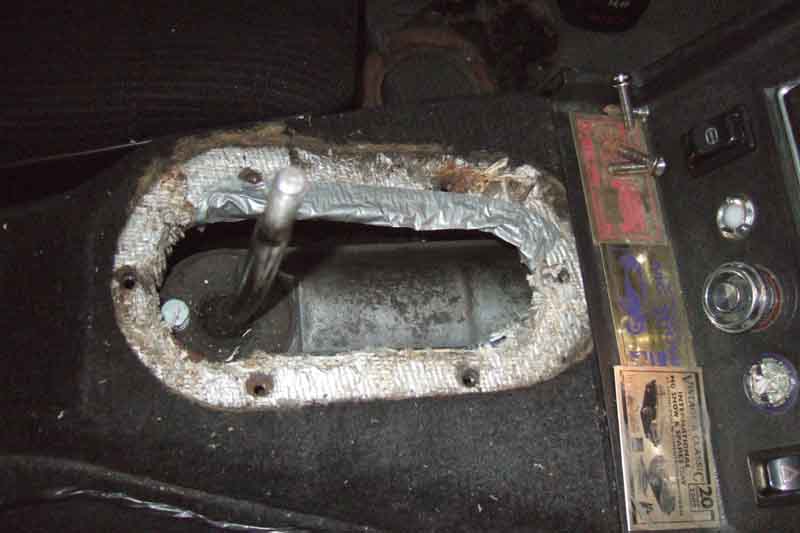
Duct-tape over the edges of the hole to protect hands. Bee and Vee have thick silvered sound and heat insulation material over the tunnel so no gasket AHC188 under the panel but a pal's 78 is just painted metal - no insulation - and has the gasket:
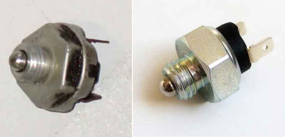
Vee's original OD switch on the left and a modern replacement on the right. The original design means that you cannot get a socket or ring or box-spanner over the end of the installed switch, only an open-ended or grips from the side, which isn't possible with the 4-synch OD switch with the gearbox installed. On the modern switch the hex is the widest part, meaning a socket or box-spanner can be used, making removal and replacement on an in-situ gearbox easier. With a 16-point socket on a 1/2" extension bar the socket will go but with a very limited 'throw'. But by turning the socket on the bar 90 degrees at a time you can effectively get 32 points:
Switch out, wires tied to the gear lever to stop them dropping down out of reach:
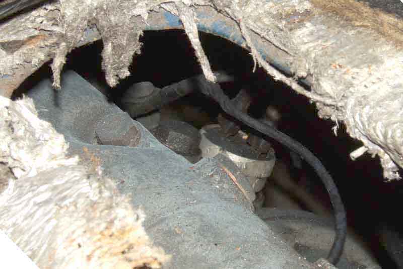
Reverse light switch - different orientation, so can be reached from below with grips:
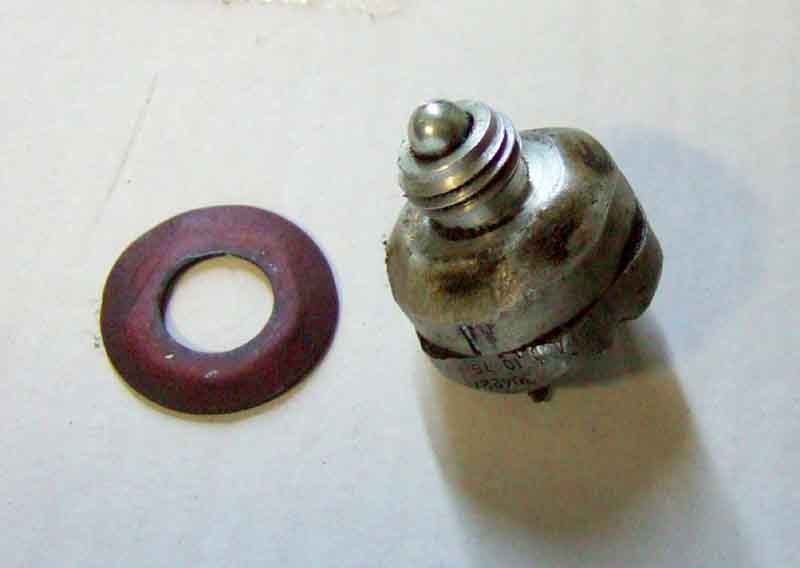
Typical switch and spacer. It's always been said they are fibre and there are two per switch. However Vee's OD switch spacer (here) is copper and there is only one. Most suppliers show it as fibre, and only one (as does the Parts catalogue) but Brown & Gammons shows the reverse light switch spacer as fibre and the OD spacer as copper, the same part as the master cylinder banjo washer:
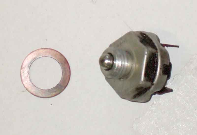
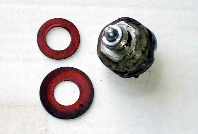
Vee's reverse light switch and spacer. One fibre, thinner than the copper OD spacer above, smooth all over so not squashed down by the switch:
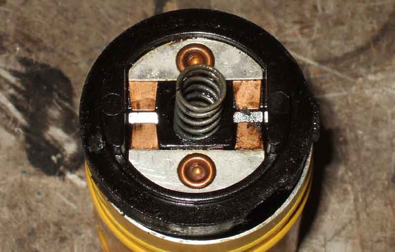
The plunger end, with the moving part consisting of two contacts. Very oily - and sulphurous, so gearbox oil has worked it's way up and in, rather surprising seeing as the switch is at the top:
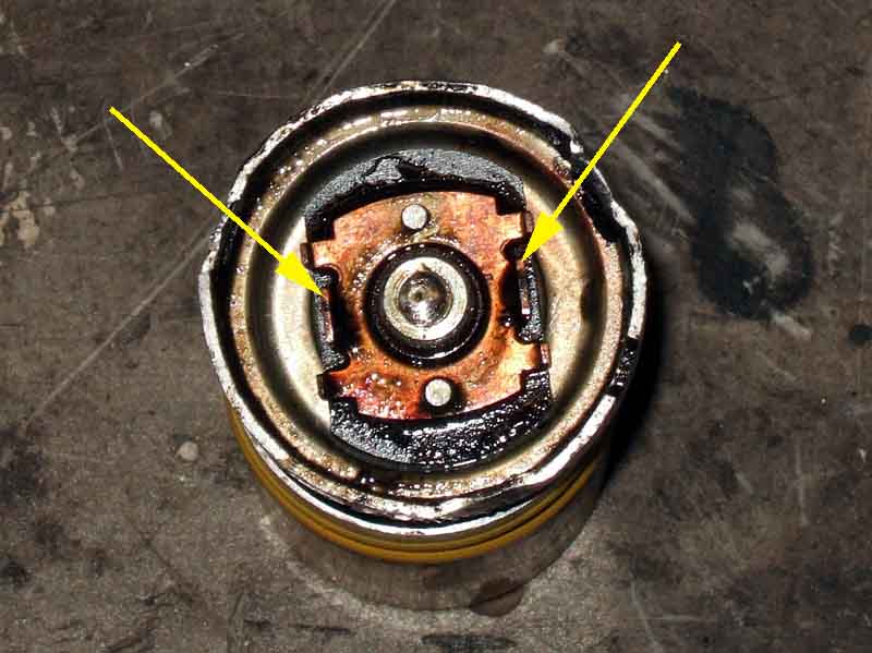
The terminal end, with the fixed contacts. Two pairs - each bridged by one of the moving contacts, so two chances of making a good connection, particularly should the one that makes and breaks first becomes burned:
Once cleaned of oil very little signs of burning, so I don't know why operation had become erratic. This switch operated with quite a small movement of the plunger, but then became erratic as the plunger was moved further, and needed very firm pressure at full travel to make contact again:
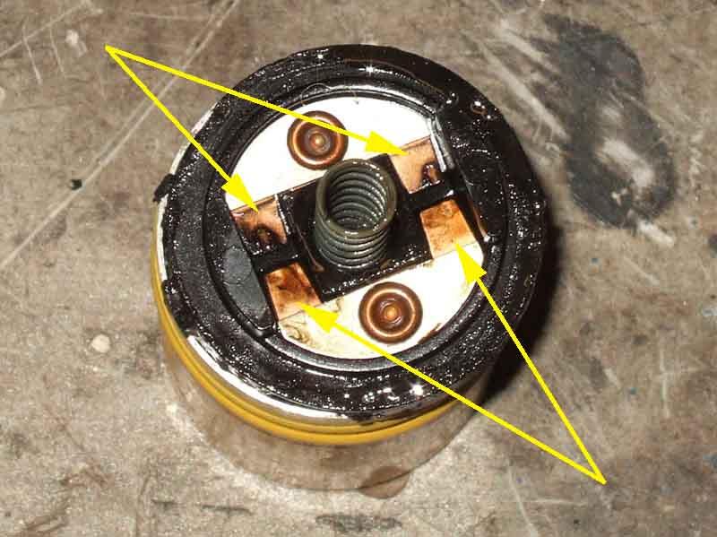
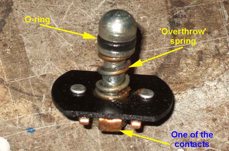
Plunger with a O-ring (hasn't kept oil out!) and an 'overthrow' spring ... not for 'come the revolution', but to allow the plunger to carry on moving once the moving contacts have reached the fixed contacts:
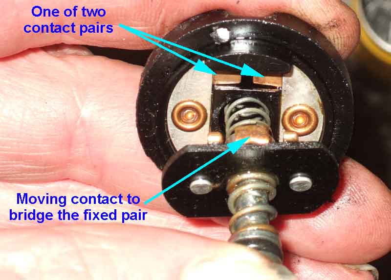
Each moving contact bridges one pair of fixed contacts, and either will allow current to flow. No less than 18 individual components:
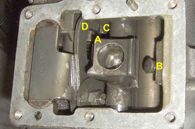
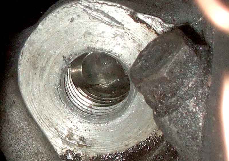
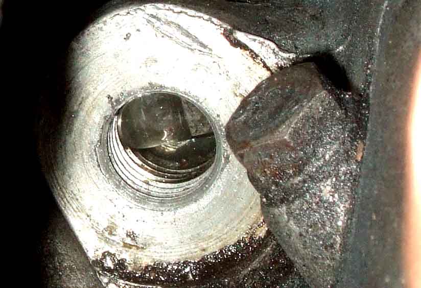
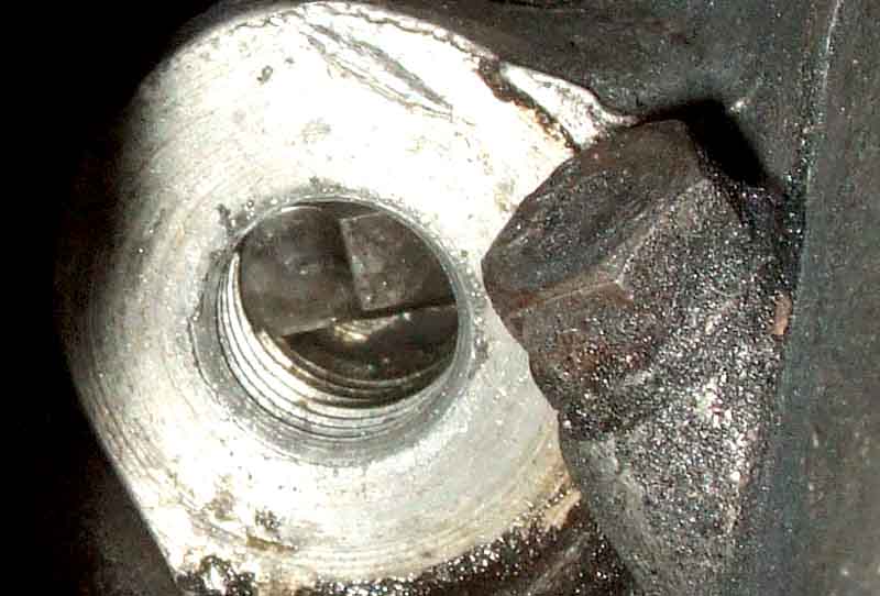
Reverse switch actuation: As the gear lever is moved to the left the selector lever (A) moves to the right and depresses the switch plunger (B) to operate the switch. As the gear lever is pulled back to go into reverse gear the selector lever moves up and keep the plunger operated. Also as the lever is pulled back a finger on the selector lever (C) slides up between the jaws of the reverse gear detent D. If the reverse gear detent is not in the correct position, for example if a forward gear is still engaged, the jaws of the detent will not be in a position to allow the finger to move forwards and so reverse gear will not be selected:
OD Switch actuation: 4-cylinder - round shaft, notch under the switch in the reverse and 1/2 plane, with a smooth transition at it moves to the left to activate the switch anywhere in the 3/4 plane. This gearbox uses selector lever 22B386 and isolation switch plunger 22B406:
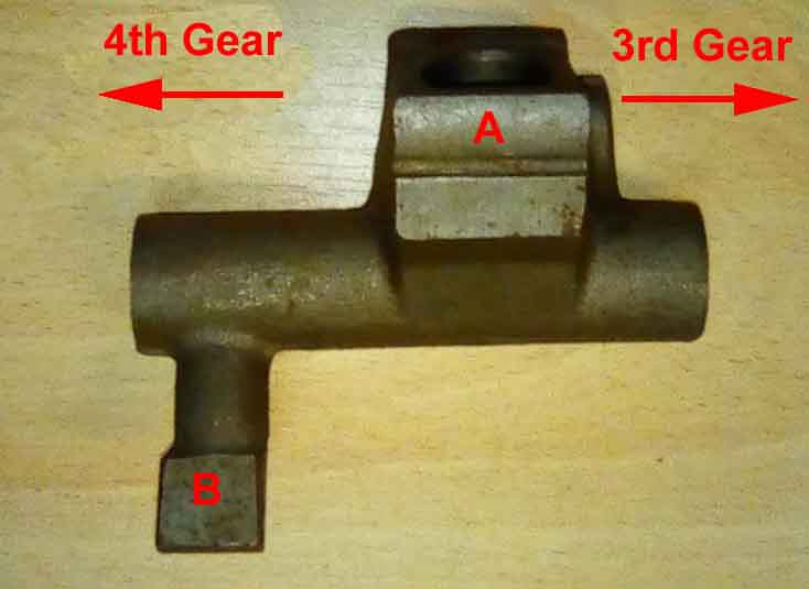
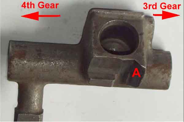
4-cylinder selector lever 22B386 giving OD in 3rd and 4th. As the gear lever is moved to the 3/4 plane face 'A' moves towards the viewer and operates the OD plunger 22B406 to actuate the switch. As the gear lever is moved in a straight line between 3rd and 4th face 'A' keeps the plunger operated and the switch actuated. 'B' is the finger that prevents Reverse being selected if the interlock is not in the correct position: (Oliveira & Valentim)
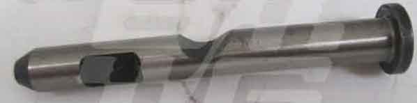
This picture of the 4-cylinder OD plunger 22B406 is from a V8 register article, and they don't seem to be available.
Someone on the dreaded MGE says Moss Europe show it as the same as the 4-cylinder reverse plunger (pictured here 22B396), but they don't now. And there is a significant difference between this and the OD plunger in the V8 Register article in that the 'anti-rotation' and switch cut-outs are at right-angles to one another, as well as being reversed along the pin i.e. here the switch cut-out is closer to the head whereas in the picture of the two OD plungers the 'anti-rotation' cut-outs are closer to the heads: (Brown & Gammons)
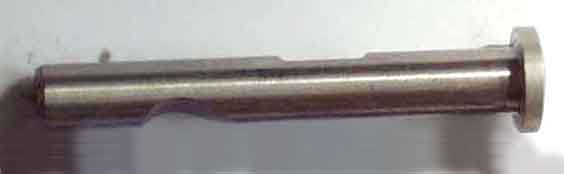
V8 with OD on 4th gear only - similar notch under the switch. This gearbox uses selector lever 22B726 and isolation switch plunger 22B727:
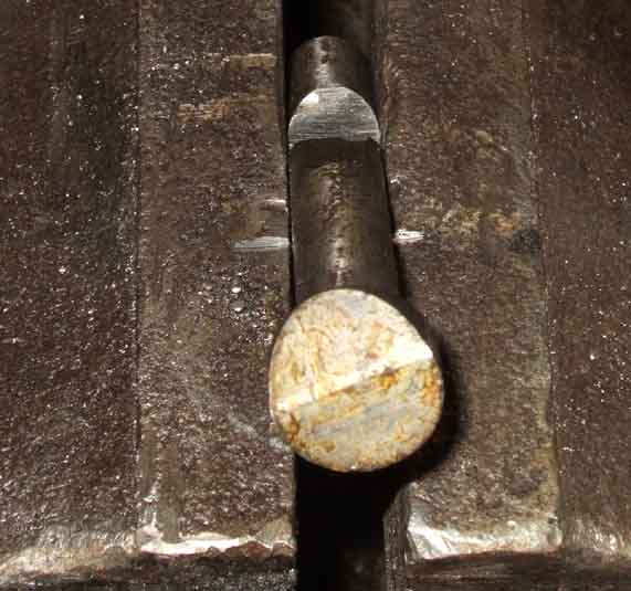
Normally the plunger only moves to the left as 4th gear is selected, and on Vee only goes about half-way, and has a different shape with a sharper transition than the 4-cylinder plunger:
Once in 4th if the lever is pulled further across towards the driver the plunger moves even further, which is not a problem. But when in neutral and 3rd gear it also starts to move if pulled across like that, so adjustment of the switch spacing is pretty critical. With a new switch and a thinner 40 thou spacer (in an attempt to get a more reliable engagement) the switch was operated all the time. With the original 50 thou spacer the switch operated reliably with the gear lever used normally, but it also operated if pulled towards the driver in neutral and 3rd. It took an additional 15 thou of spacing (front wheel bearing shims!) to stop that happening, but still leave it operating in 4th:
V8 selector shaft 22B726 giving OD in 4th only. As the gear lever is moved to the 3/4 plane the socket in the selector lever moves towards the viewer. But it is only when the lever is moved into 4th gear that face 'A' moves to the left to contact the plunger, and actuate the switch:
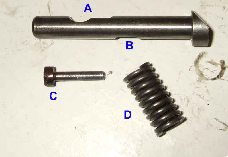
V8 plunger 22B727, with a 2-stage switch cut-out at A, location cut-out at B, location pin 22H576 at C, and return spring 22H204 (NLA) at D. The location pin prevents the pin from rotating to keep the switch cut-out under the switch. The fatter and chamfered head allows for a smoother operation of the plunger and switch than a flat head:
I bought a replacement to see if I could modify it to get more movement of the switch button and immediately noticed that the chamfer is at a different angle to the cut-out. I didn't notice this with the original, and it doesn't appear to be the case in the above picture:
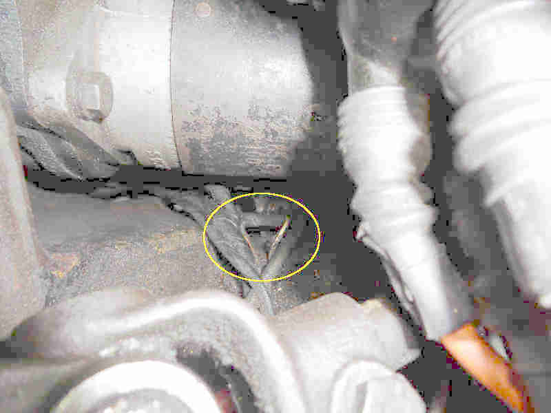
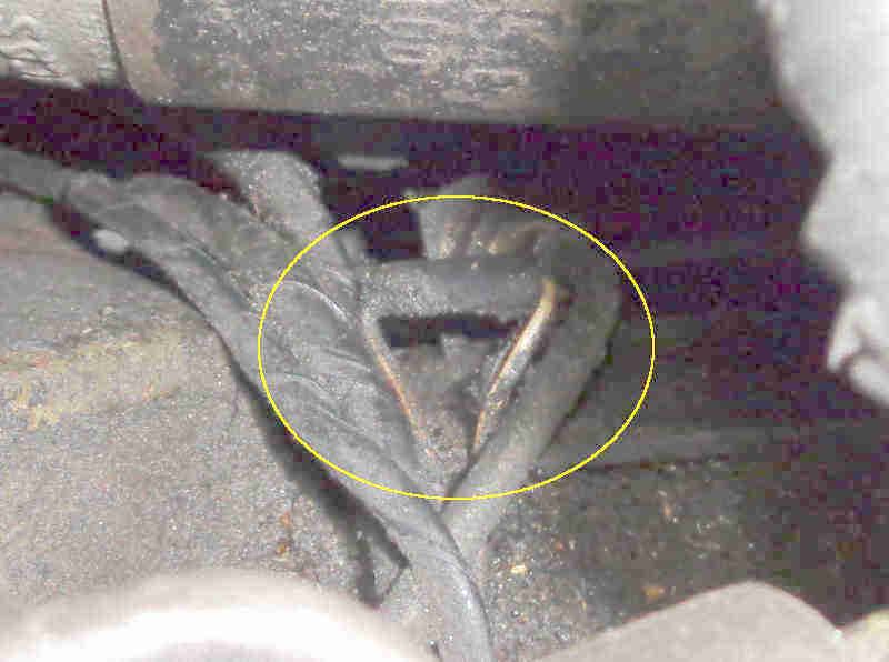
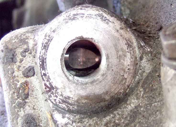
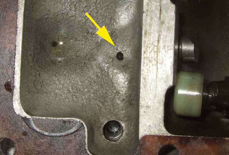
The location pin can be drifted out through the hole on the underside of the tower arrowed, and the plunger and spring withdrawn. The smaller hole to the left is a drain hole, so any oil that gets down the sides of the plunger is pumped back into the gearbox as the plunger is operated, otherwise it would be forced into the switch and probably leak out from that:
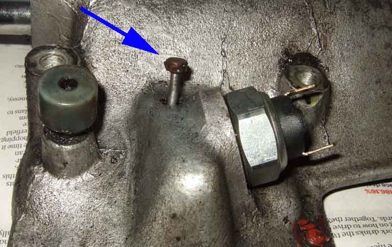
The pin partially drifted out. On replacement make sure the plunger is correctly aligned before tapping the pin back home:
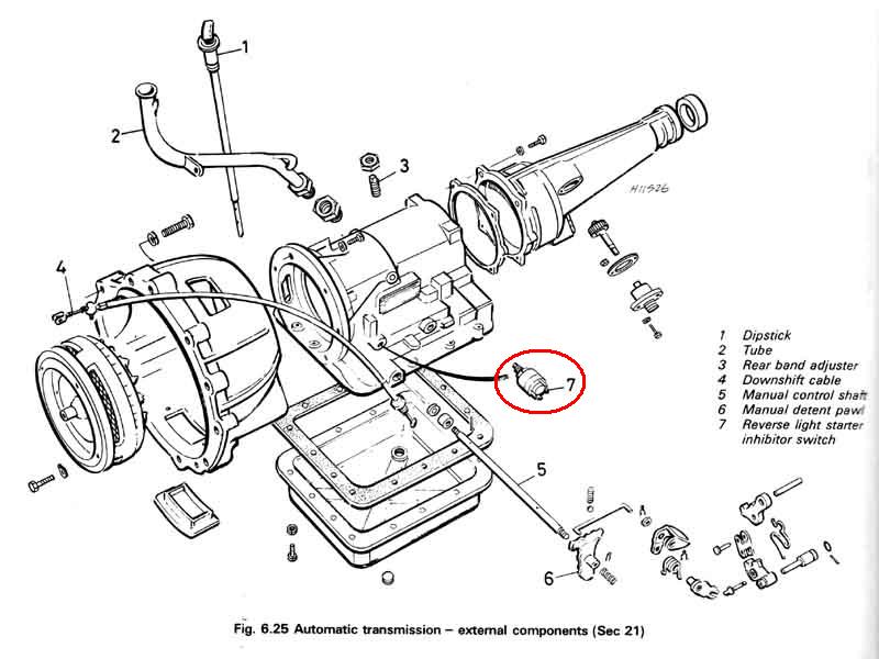
Kick-down cable and switch:
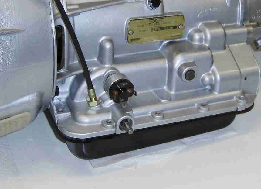
The switch and its connections. Click the link for the adjustment procedure: (Chris Witor)
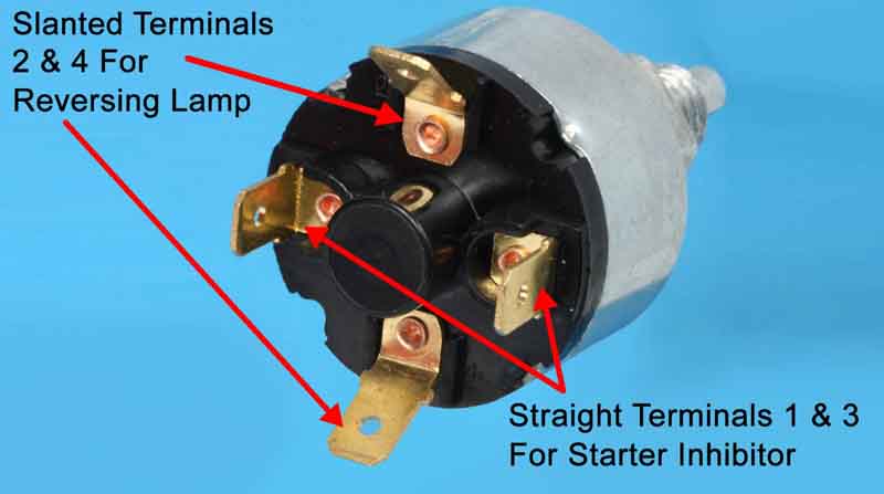
The gearbox sub-harness has green and green/brown wires for the reversing light circuit that connect to the same coloured wires in the main and rear harnesses in the mass of connectors by the firewall. The starter inhibitor has two white/red wires that connect to the same coloured wires in the tail from the main harness that leads down to the starter in all Mk2 CB cars. With a manual gearbox these two wires in the tail are connected together with a 2-way bullet connector just above the clutch hose bracket: