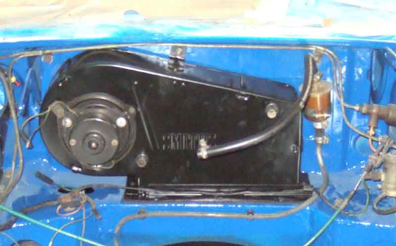
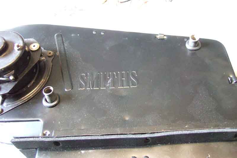
The heater unit. This is a 77 and later version with the two-speed resistor fitted inside the heater unit. The earlier single-speed is much the same but without the resistor wiring and just two wires connecting to the main harness with bullets instead of a 3-pin plug and socket. (Image from Paul Depper)
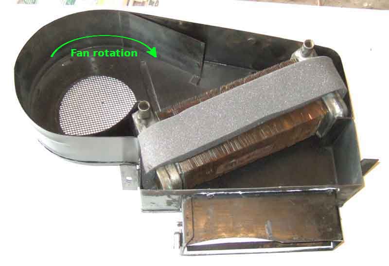
People have wondered why the inlet is at the bottom and the outlet at the top when natural convection works the other way. That's because the heater doesn't work by convection but by pumped flow, and the other way round that flow would have to push air downwards through the matrix when refilling a drained system. As it is the air rises as coolant is introduced and is flushed out without specialised bleeding techniques. The flow is sufficient to push the air along the return pipe above the rocker cover and down into the bottom hose, and from there to the top of the radiator.
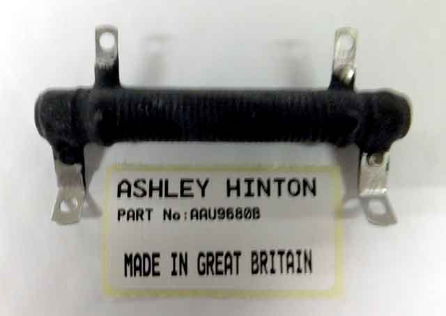
Resistor unit inside the casing of 2-speed heaters. (Photo from Ashley Hinton)
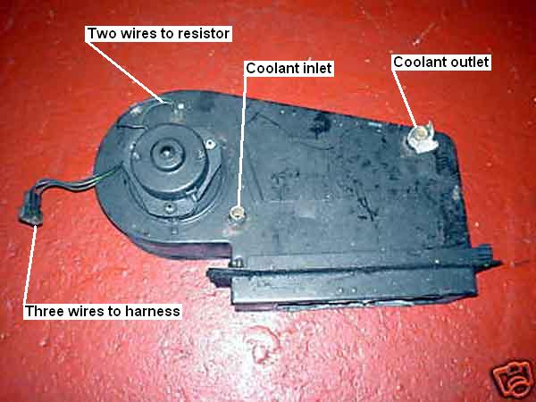
Back of the heater unit, pre-77 with just two bullets connecting the motor to the main harness. This is a very early unit, later units had a mesh screen over the cold air inlet to prevent leaves entering from the air-box and clogging the heater unit. The circular seal prevents fumes from the engine compartment being drawn into the passenger compartment, and gets the maximum benefit from the ram effect while moving. (Image from Leyland Parts Catalogue)
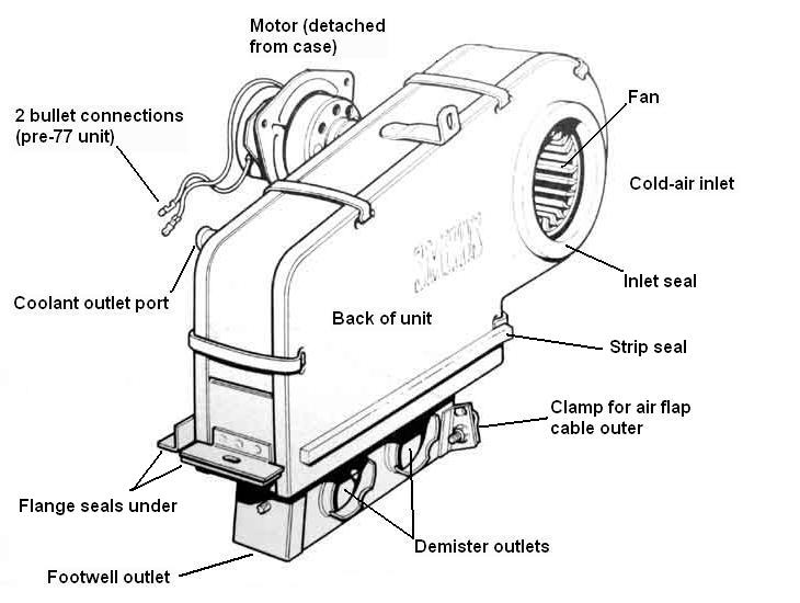
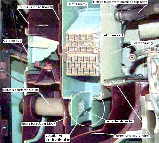
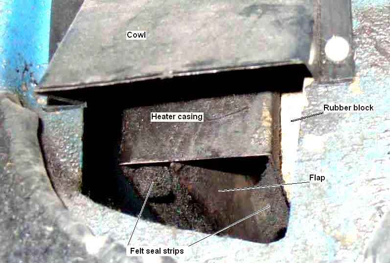
Clausager has this very useful photo of the Gaydon cut-away engine on page 62 which shows the heater tucked away in the corner of the picture. I've labelled it with its main components and the body structure around it, plus the separately operated cold-air flap. Unfortunately the air direction flap appears to be missing from the heater unit.
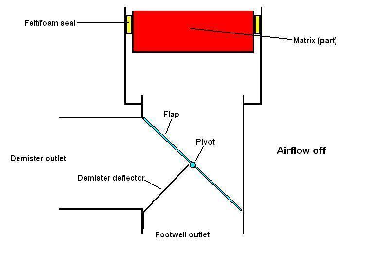
The next three pictures show how the air flap controls direction. In this position both demister and footwell vents are closed off.
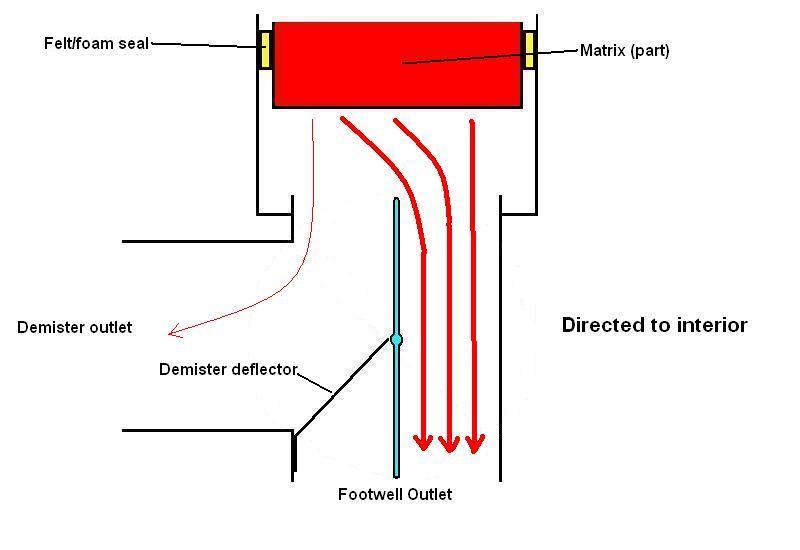
In the central position of the dash control the flap is straight up and down. On the face of it this appears to direct air to both demister and footwell. However the longer, narrower and more tortuous past to the demister means relatively little air escapes this way (it can be felt), the majority does flow to the footwell. The demister deflectors are only positioned immediately in front of the outlets, so either side of those air is going to go straight down anyway.
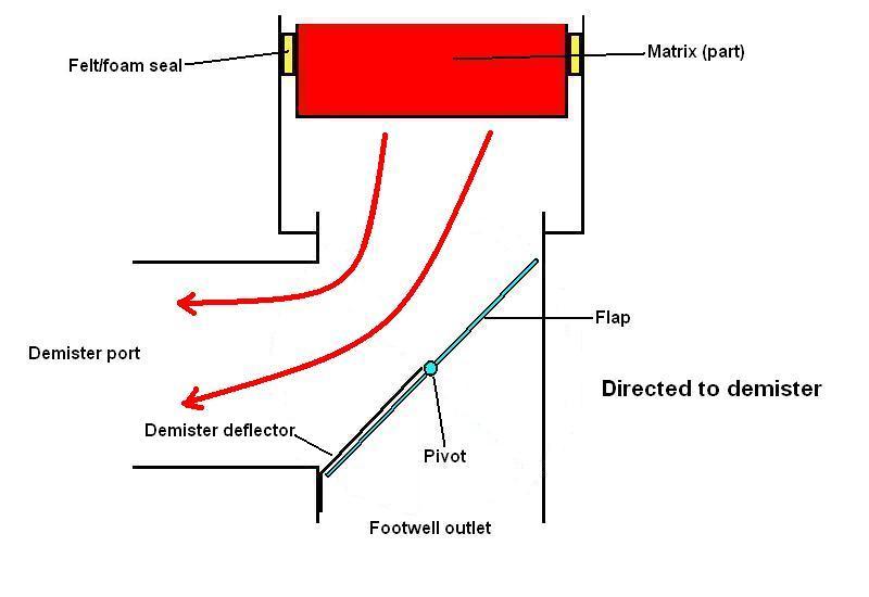
Flap turned to the other extremity closing off the footwell vent, all air being directed to the demisters. This begs the question of why the demister deflectors are there at all, as the flap in this position makes them redundant. You could say that they found some air to the demisters all the time was beneficial in keeping them clear, and the deflectors were needed to make sure some got through. But that is surely asking a lot for BL/Smiths in the 60s!
The passenger side in the V8. The flap is shown in the Interior position i.e. more or less straight up and down. You can also see some felt strips which are beginning to come adrift.
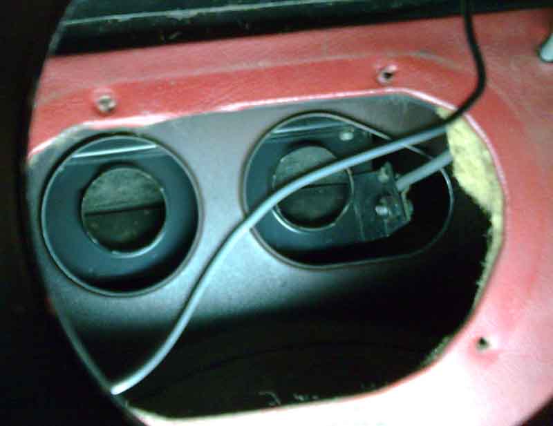
Mk1 roadster showing the screen demister outlets on the heater unit, air direction cable to the right, support plate for straight pipes and flexible hoses removed (image from Dave O'Neil). This 'egg-shaped' hole for the right-hand demister tube and direction cable makes it very difficult to fit the heater with the cable already attached to the heater unit.
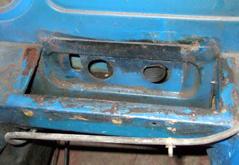
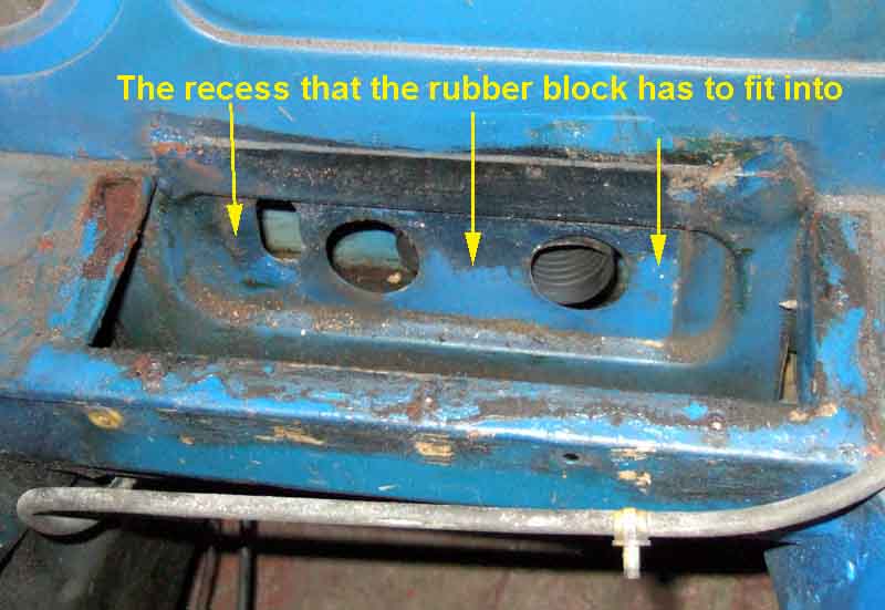
Unlike this later arrangement with the separate tall slot, probably from the start of the 1971 model year when a number of changes were made. This also clearly shows the recess for the rubber block used from the same date that surrounds the demister tubes and cable ...
... compare with the earlier flat surface here. Cutting a slot up from the side of the earlier egg-shaped hole to where the top of the later separate slot is, to allow the heater unit to be refitted with the cable already attached. (Chicagoland MG Club, scroll down to 'P.P.S. - Oct 09, 2003')
The off-side footwell and the cable for the air flap - earlier arrangement with the adjustable footwell vents. Just about possible to reattach the cable with the heater in position.
Another view from Pete Curtis. Pete writes "Definitely a two person job so had to rope in the youngest (bribed with a hour driving lesson) to adjust the cable inner from the dash end. Used a new cable which was much smoother and didn’t have a kink like the previous photo where it had been secured previously. Using the magnifying app on the phone wedged up against the vent hole was much more comfortable than trying to wedge my head into the small space. In all I’ve probably spent about 4 hours trying to poke a wire through a tiny hole. My wife can’t work out why I’m so elated now it’s done. Thanks for all the advice." I suggested slackening the trunnion screw at the control end, withdraw the inner until the end was just short of the trunnion in the heater flap, then use long-nosed pliers to push the end of the inner through the hole in the trunnion. Someone else suggested using a nut driver to hold the trunnion in the correct position while doing that. Another possibility is to remove the pedals to give better access on an RHD. Once you have got the cover off (which can be tricky in itself) pre-77 cars only have a single pivot-bolt through the clutch and brake pedals so it is relatively simple to disconnect the clevis pins and return springs and withdraw the bolt towards the heater to lift out the pedals - I have certainly had Bee's clutch pedal out more than once that way:
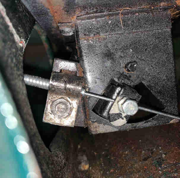
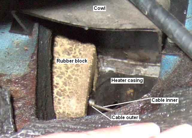
The later arrangement with the fixed footwell cowl and rubber block. It can only be shown in two separate pictures on an RHD as the pedals get in the way. Note the rubber block, the clamp for the cable outer is covered by it, making undoing or fastening without cutting into the block impossible.
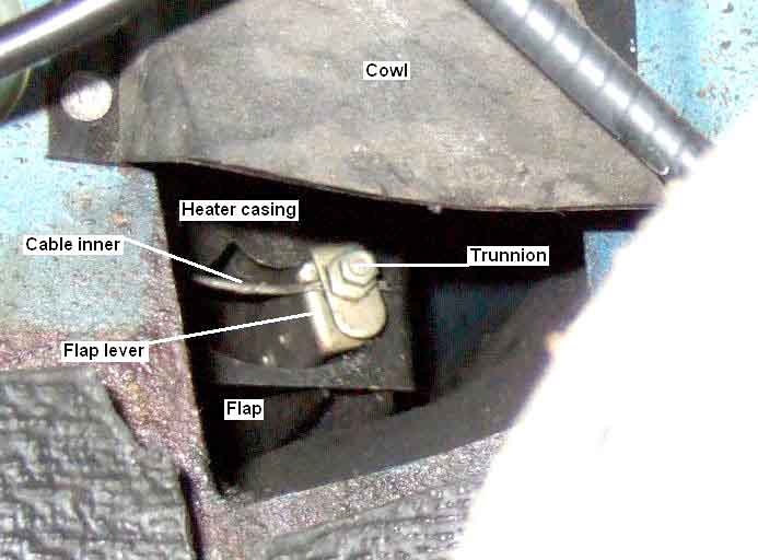
The inner fastening to the flap lever, shown in the Off position. This looks to be more accessible but I can only just get a finger-tip to it, although access would be better with the cowl removed. You would still need to manipulate the end of the cable with a pair of very long nosed pliers, and the trunnion with a nut driver on an extension, you wouldn't be able to see the hole in the trunnion, and the pedals on an RHD prevent you looking straight into the space! All in all a difficult proposition even if you were only replacing the inner. This seems to be a stranded inner, but logic dictates that it should be solid as it has to push the flap closed as well as pull it open, and there is no spring to aid closing. I must be fortunate in that this flap is very easy to move. Interestingly my mate Terry with a 73/74 reports that his also seems to be stranded as is my 73 roadster, whereas his replacement from the MGOC (original chopped off both ends when the heater was removed by a PO) is solid. I've come to the conclusion that a stranded cable is fitted as these are much more flexible, as the cable has to cross from one side to the other behind the dash to get from the heater unit to the dash control.
Vee's footwell channel, with the felt strips loose and partly blocking air-flow. I removed six, which seems overkill, in one position there was one on the movable flap and another on the side of the channel it moved against.

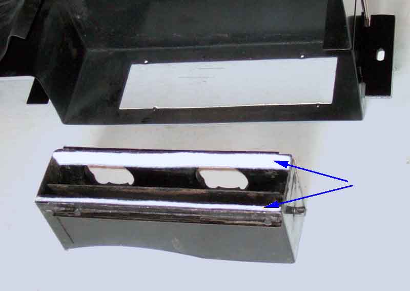
The section that contains the air-direction flap is screwed to the bottom of the main case, so can be removed making cleaning and replacing the felt easier. I used 3mm felt from a hobby-shop and felt (ho ho) that four pieces stuck to both sides of the channel top (arrowed) and bottom was thick enough to form a seal with the moveable flap at either of its extremities of movement, with minimal restriction.
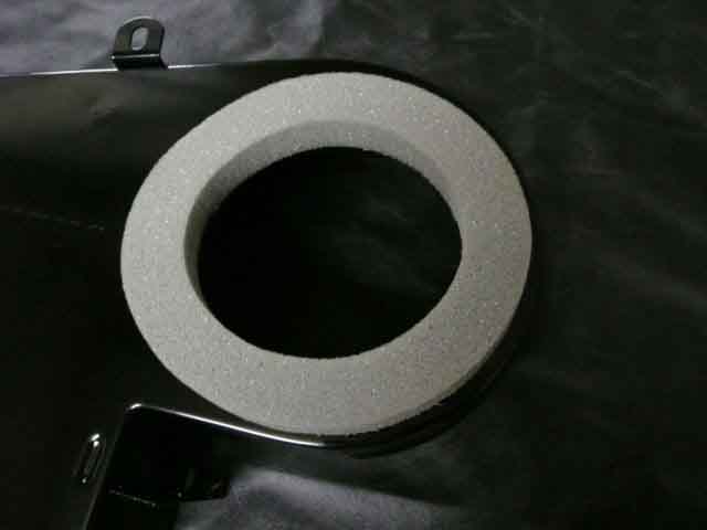
The foam seal that goes between the back of the heater casing and the bulkhead to seal the air inlet. Photo from Ashley Hinton. However this is low-density, the original is either rubber or high-density foam and more robust, so when refurbing Vee's heater I left it in place.
The seal around the matrix. Seals the ends as well as the sides, so air can only pass through the heater by going through the matrix core.
The grommets (7H1993) round the matrix ports
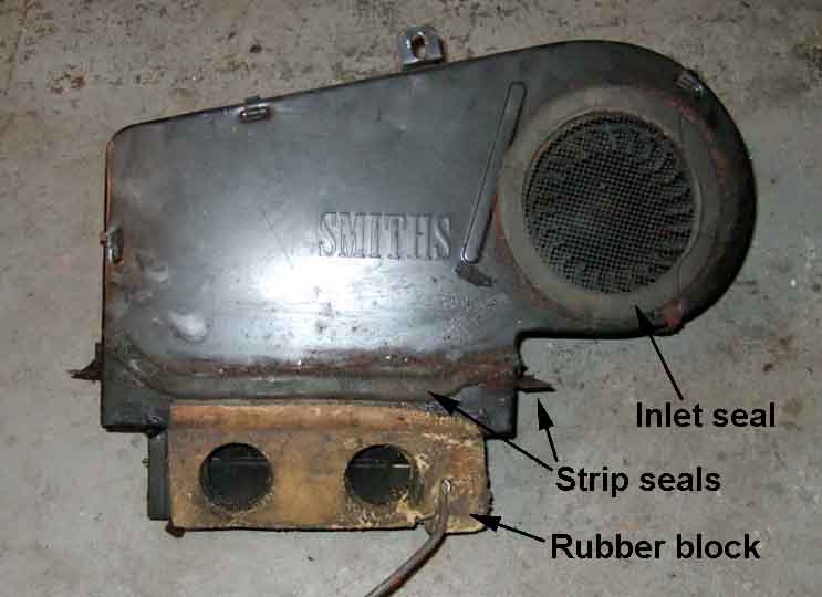
The dreaded rubber block that goes between the lower back of the heater box and the inner bulkhead (Watford Classic Cars).

At first I though Vee's would be reusable, saving me some grief. But on trying to remove it carefully to clean the case it was crumbling. Note the strip seal just above the rubber block, which together with three other pieces under the flanges that screw to the bulkhead shelf prevent engine bay fumes getting into the cabin. Certainly the one on the back is rubber or high-density foam, if I found anything under the flanges it just crumbled away as I scraped it. Replacements for these are also low-density foam, but I have some sticky-backed high-density strip which is more robust. Looking at the whole shebang I don't think the rubber block does anything more than wedge the heater unit into the bulkhead cavity to stop it rattling, and to seal the demister pipes. It can't seal against engine bay fumes as it doesn't go the whole width of the heater, let alone the cavity, it's the four strip seals that do that.
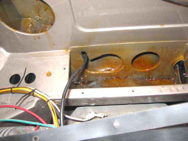
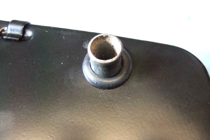
Engine compartment side, on Vee (1975), corrugated tubing visible behind the panel. These just push into the rubber block which fits into a recess in the bulkhead.
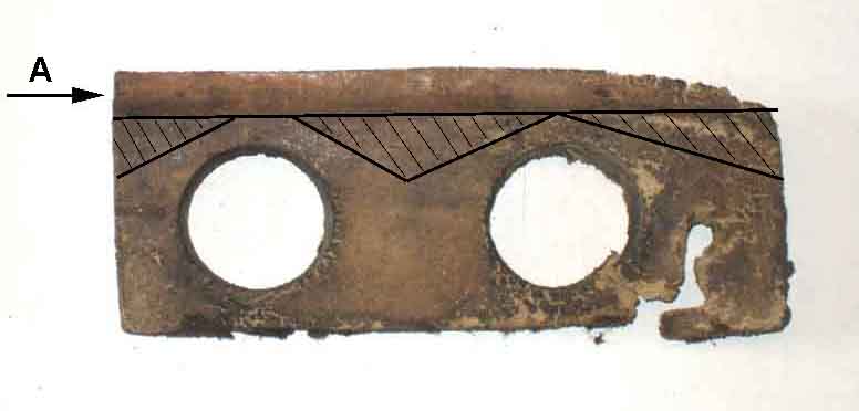
The block gets thicker towards the top, so has to be compressed more and more to fit into the recess. At point 'B' it is being compressed by half to the thickness at 'C'.
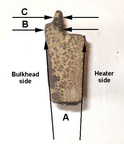
'A' is the thinner part of the block that is above the recess. There may be some scope for thinning the block at the shaded areas, so there is less to compress.
New block trimmed with a craft knife, leaving the full thickness of the material around the vent holes. As suspected the bottom of the heater was 1/4" forwards of where it needed to be to be pushed down into the cavity. But daubing both the face of the block and the back of the cavity with Swarfega as a lubricant, as well as reducing the thickness over most of the upper edge, allowed me to wedge the left-hand corner in:
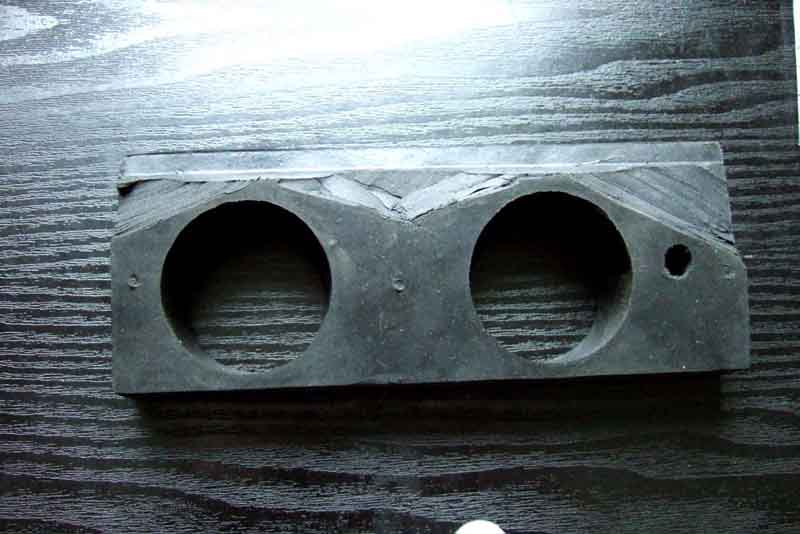
After that pressing down and wiggling got the rest of the bottom of the heater into the cavity, then pushing straight down was relatively easy - especially with no engine!