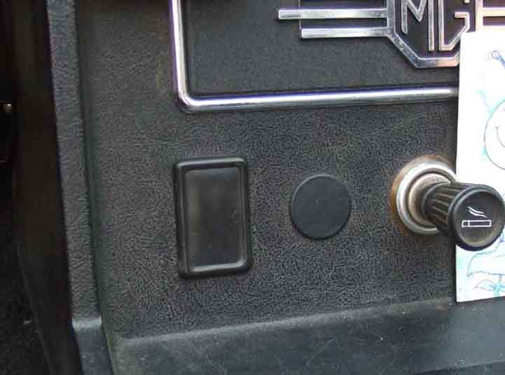
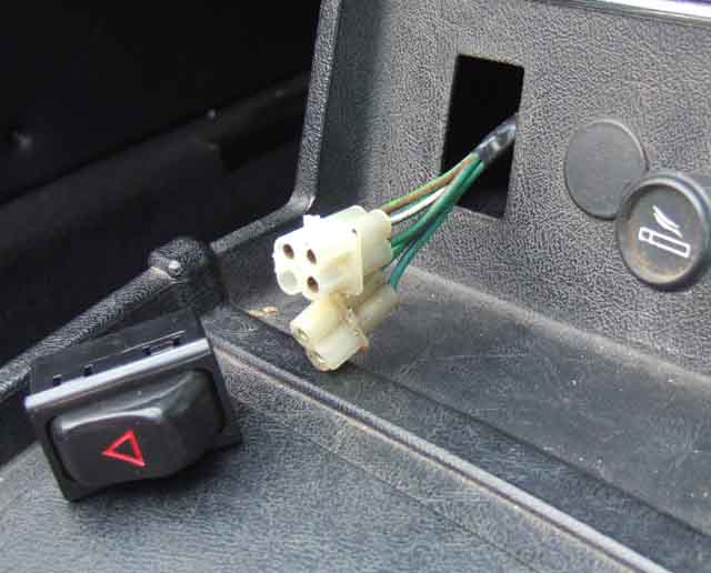
I didn't like the kits with the combined switch and flasher unit that you have to find somewhere to mount, and opted for the pukka rocker switch as I had a convenient blank on the centre console used for the 1972 model and later:
Googling found the switch at Chic Doig Classic Sportscars Ltd, someone who I've been aware of in the MG world for a long time, at the reasonable price of £12.49. Ordered in the afternoon it arrives at breakfast time next morning - how quick is that? But I open it up to find it is a lighting switch instead of a hazard switch. Get on the computer to complain, to find an email from Chic to say that he realised he had sent the wrong thing, and had already sent the correct switch and to keep the lighting switch. I can't guarantee everyone will get a free lighting switch with each hazard switch, but again, how good a service is that?
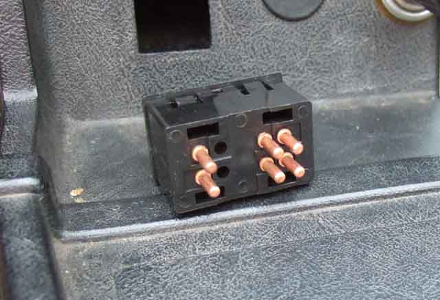
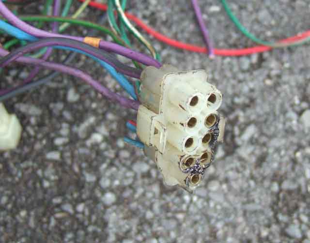
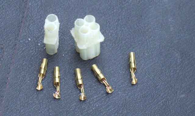
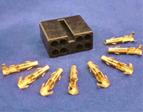
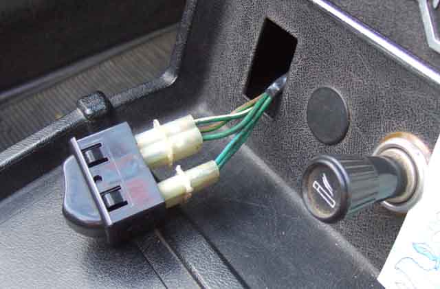
... but they have round pins instead of flat spades
More browsing for a hazard flasher leads me to Autopower UK Ltd, and I commit to buy at £8.79 before suddenly realising it is an indicator flasher i.e. only capable of flashing 2 x 21W, whereas you need a minimum of 4 x 21W, or 84W. Most these days are capable of flashing an additional pair of 5W side flashers and are marked '4 x 21W + 2 x 5W' or 94W in total. It's complicated by markings often showing '2/4 x 21W'. A hazard flasher should be capable of flashing anything from 1 to 4 lamps (plus side flashers), as one or more corners may have been damaged in an accident when you turn them on. Don't think that because it shows it will flash two bulbs, you can use it as an indicator flasher. Indicator flashers work differently in that they are designed to flash two and only two corners (plus side flashers), more than that will burn it out, less than that will not flash at the correct rate, which is a deliberate safety design feature to indicate (no pun intended) to the driver that one of the bulbs has failed. Also indicator flashers light the corners of the car as soon as the column stalk is operated, then after a short delay start flashing off-on-off-on. This is another safety design feature to give the earliest possible indication to other road users that you propose to change your lane or direction. By contrast hazard flashers do nothing when you first turn them on, and only after a short delay do they come on and start flashing. That delay in first coming on is unacceptable for indicator flashers. Any road up, as they say. I contact the supplier and they say that if I complete the transaction they will send me a hazard flasher instead, which duly arrives - again very good service.
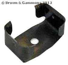
As the hazard flasher unit has the same size and shape top as the indicator flasher I could have purchased clip BHA 4780 from several of the usual suspects and screwed it to the bulkhead beside the indicator flasher. However I opted to cable-tie it to the cross-brace by the steering column instead. So for just over £20 I have the main components. eBay kits are more than £40, and some aftermarket kits don't isolate the indicator circuit when the hazards are on which can be dangerous as described here.
The switch has round pins for a multi-way plug rather than spades, but I have an old harness from the rewire of a 1980 many years ago that will have had hazards, so can cut out that plug and the appropriate length of wiring to fit Bee. However I search the harness and can't find it, and subsequently realise I had already cut out the plug for a pal who was fitting hazards to his roadster! Never mind, late harnesses had a separate dash harness with three multi-way plugs and sockets connecting it with the main harness. The switch has four pins in one block (the 'hazard' connections), and another two spaced further away (the indicator flasher connections). The spacing in the harness sockets is such that it will fit the block of four, or the block of two, but not all six. So I cut the socket up into a block of four and a block of two! :
It should be possible to remove the pins from the wiring side of the socket but it needs a tube of a precise internal diameter to fit over the business end to compress two little tangs, and thin-walled enough to fit between the pin and the tube in the socket. I spend a little time swaging down and drilling out a length of aluminium tube to make such a tool, without success. But then as I'm going to cut the wires off the pins and attach new wires of the correct colours, I simply push the pins all the way through the socket body from the wiring side. Although the block of four and the block of two seemed to be making a firm connection to the pins I test-fitted each pin once removed from the block. It's a good job I did as the switch pins are a smaller diameter than those in the 'male' half of the multi-way connector, so I pinch up the females a little to make a more certain connection:
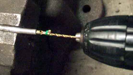
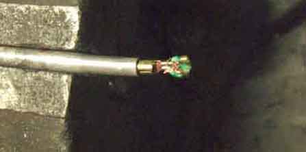
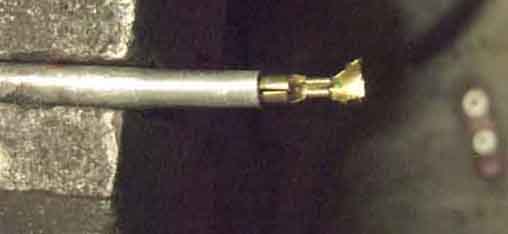
I want to solder the wires to these pins, which have been spot-welded then crimped round the insulation. I use a very small drill through the cut end of the wire to remove it and open the outer insulation crimp up a bit, then use pliers to open it up fully and remove the strands of copper and remainder of the insulation:
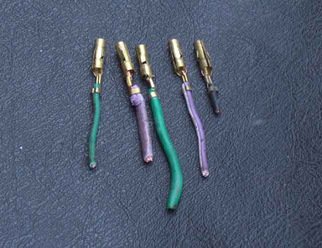
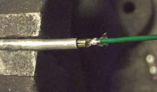
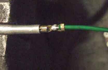
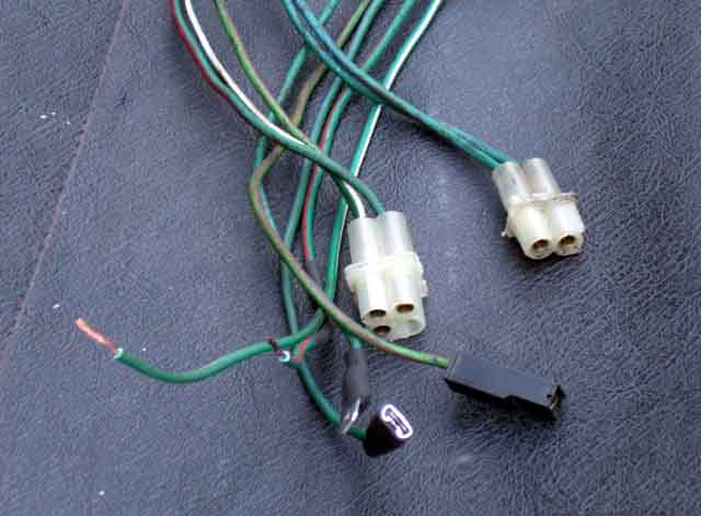
Five wires of the appropriate length to reach from the hazard switch to the column switch connector and indicator flasher, which are conveniently close together, are cut from the old harness in the correct colours: Two lengths of green for the indicator flasher, green/white and green/red for the flashers, and light-green/brown for the connection to the hazard flasher. Soldered to original inner conductor crimp, and closing the outer crimp around the insulation makes a neat connection:
After all that I found this from Autosparks which looks like it should fit, although subsequently heard of the same thing from Holden which is cheaper:
The pins are then pushed into the socket bodies from the wiring side - light-green/brown, green/white and green/red to three of the block of the four, and the two green wires to the bock of two. The three wires can go on any of the four pins as with the hazard switch off each of these pins is isolated from everything else, and with the switch on they are all joined together (but nothing else). The fourth, unused pin would be for an additional tell-tale, but UK cars didn't seem to have this, and you already have the two tell-tales on the dash in front of you anyway. Again the two green wires can go on either of the two pins as with the switch off they are connected together (and nothing else) and with the switch off they are isolated from everything, i.e. the opposite to the block of four.
The other ends of the five wires need suitable connectors. The light-green/brown to the hazard flasher is simple - that just needs a female spade. The green/red and green/white will have to tap into those coloured wires on the harness side of the column switch multi-plug. I have had problems with Scotchlok connectors in the past, although that does seem to have been with wires that are thinner than the factory standard gauge. I've already used a pair to tap into those wires for the alarm I fitted many years ago. For some reason that alarm only had one wire to flash the flashers, but they have to be isolated in normal use or the indicators won't work! I had used a three-way 'chocolate block' connector to connect the single wire from the alarm, via two diodes to the two indicator wires, so simply added my two wires from the hazard switch to that chocolate block. I don't like cutting wires so for the greens I put a male spade on one, that goes into the factory green female that is removed from the indicator flasher, and a female spade on the other to go back on the indicator flasher. Note that if you have used the 'spare' spade on the indicator flasher as a convenient source of fused ignition power for an accessory, that will have to remain with the factory green somehow, or it won't work with the hazards on, which may not be a problem anyway:
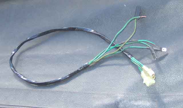
Taped up with harness-wrap (not self-adhesive tape):
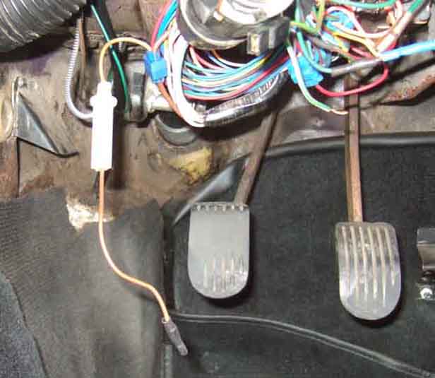
That leaves a permanent, 12v, fused supply required for the hazard flasher. I had a 35 amp inline fuseholder - again from the old harness - that already had brown wires both sides, so it was just a matter of attaching a female spade to one, and joining the other to the brown wire on the harness side of the multi-plug for the ignition switch with a Scotchlok. Again this should be reliable as they are both heavier gauge wires.
The new sub-harness is fed through ...
Power supply with in-line fuse for hazard flasher
Optional clip to mount the flasher unit on the bulkhead beside the indicator flasher (Brown & Gammons)
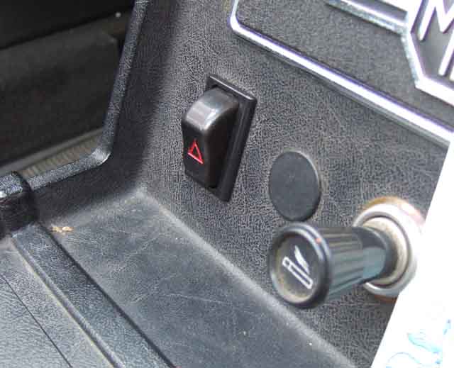
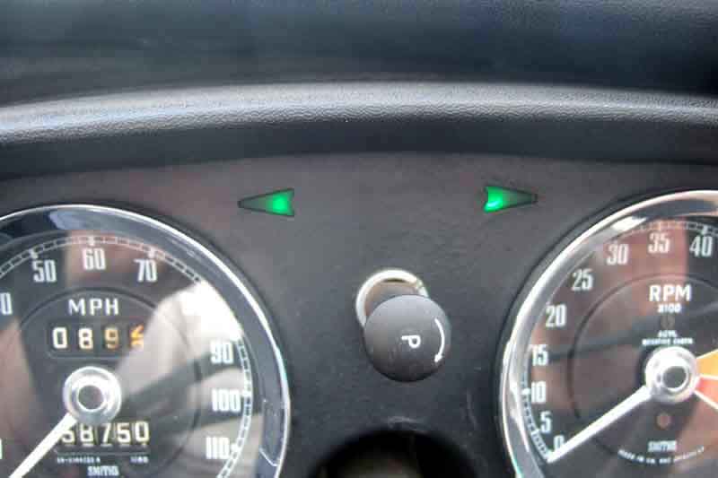
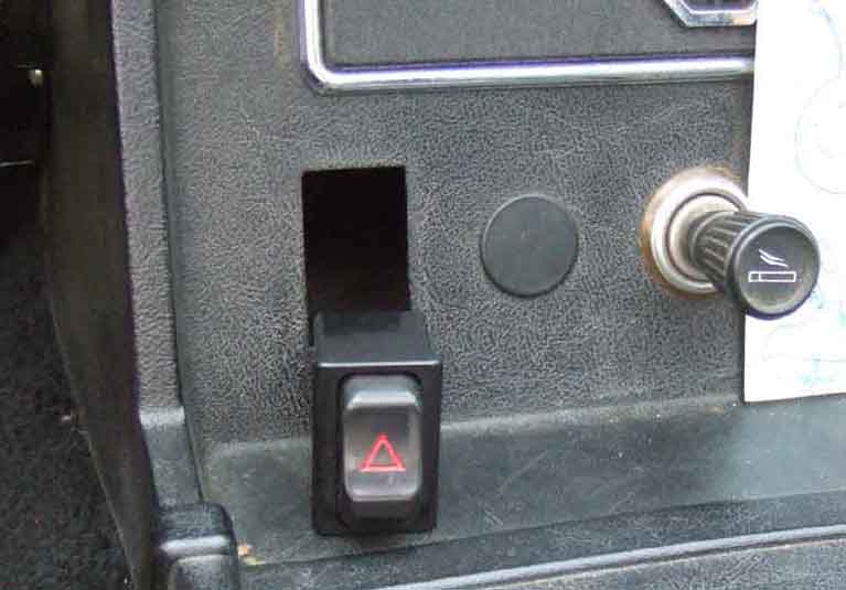
... and Bee has hazard flashers.