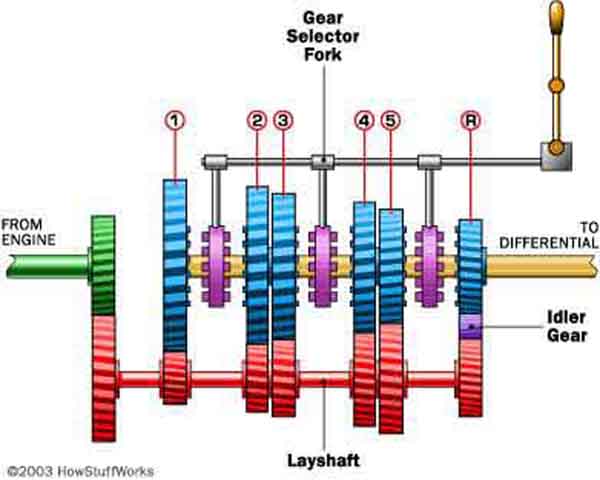
To engage each gear the gear selector fork moves one of the pink dog-clutches into engagement with one of the blue output gears, to lock it to the output shaft and provide drive through to the prop-shaft.
The additional purple idler gear between the red laygear and the blue reverse output gear reverses the direction of rotation of the output shaft when in reverse.
An oddity with this drawing is that despite each successive forward gear being larger on the laygear and smaller on the output shaft as one would expect, the laygear reverse gear is somewhere between 3rd and 4th and would give. In practice reverse is to first as indicated by the similar sizes of the 1st and reverse gears on the MGB mainshaft further down:
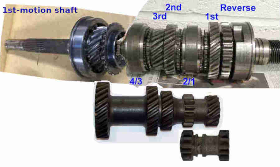
In the MGB gearbox the laygear is not used for fourth, the 4th gear selector engages directly with the drive dog teeth on the 1st-motion shaft to give a 1:1 ratio. For that reason the order of gears is the other way round to the drawing above i.e. the 3rd gear wheel is on the left of the mainshaft with the 4/3 selector between it and the 1st-motion shaft gear, 2nd gear to its right, then the 2nd/1st gear selector, then 1st gear, then reverse.
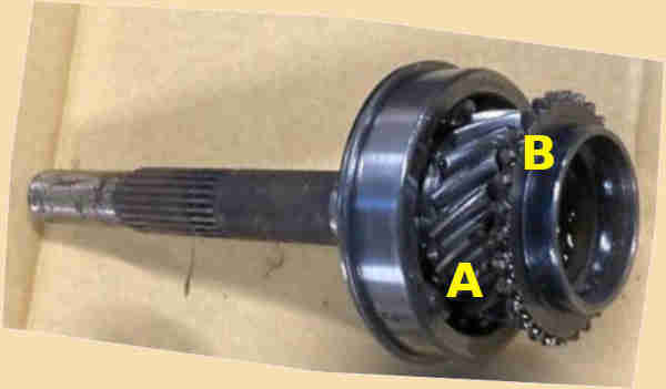
1st-motion shaft containing the gear 'A' to drive the laygear and dog teeth 'B' that the 4th gear synchroniser assembly engages with to select 4th gear:
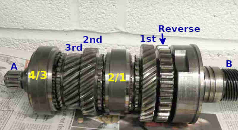
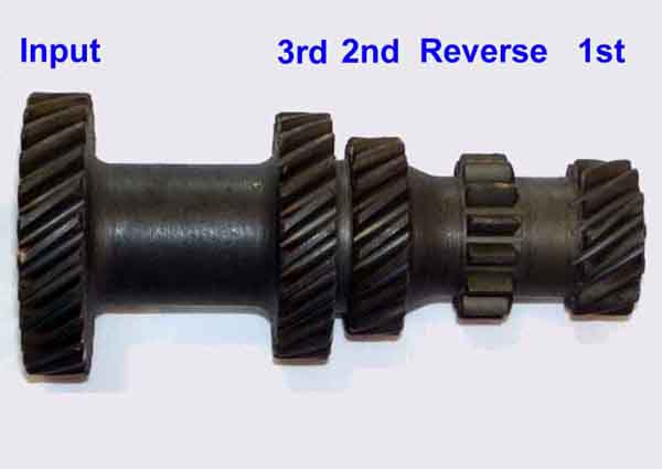
Output/mainshaft with the '4/3' synchro assembly moving left for 4th and right for 3rd, ditto the '2/1' assembly, and near-equal 1st and reverse gears. 'A' is the needle roller that engages in the end of the 1st-motion shaft to support that end of the mainshaft, 'B' is the worm gear for the speedo drive:
The laygear has 1st and reverse about the same size on the laygear - this is the 4-synch where 1st is 3.44:1 and reverse is 3.095:1 i.e. reverse has a lower ratio/higher gear than 1st. The 3-synch has 1st at 3.64:1 and reverse at 4.76:1 i.e. the other way round with reverse being a higher ratio/lower gear than 1st. This fits in with old-school advice when a very steep hill defeats 1st, which is to try reverse:
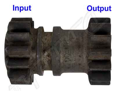
The reverse idler gear having similar input and output gears:
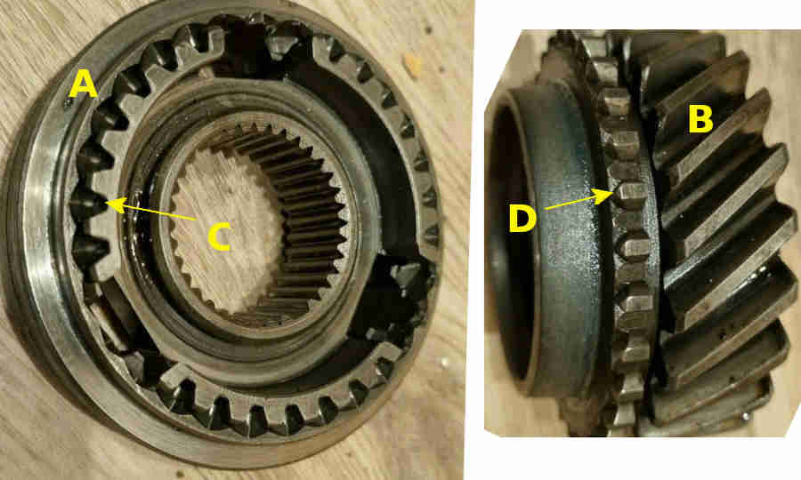
Gear selection: The selector forks move the synchroniser assembly 'A' (keyed to the mainshaft with splines) towards the gear 'B' (being driven by the laygear and spinning freely on the mainshaft). Cut-outs 'C' engage with teeth 'D' to lock the gear to the mainshaft:
In context: The large gear on the laygear is engaged with the gear on the 1st-motion shaft. The reverse idler gear shown in its engaged position, with its driven gear meshed with the laygear and its driving gear meshed with the mainshaft. When disengaged the reverse idler moves to the right with the driven gear in the space between the laygear reverse and 1st gears and the driving gear in the cut-out in the main bearing cover on the right: