
Note 1: Fitted to North American cars only. It did not use the ballasted ignition feed or solenoid bypass system, see this bulletin supplied by Allan Reeling showing how the troublesome 45DE system was replaced with the very reliable 45DM system.
Inside the external AB14 unit is the electronics module (GM in this case), plus a capacitor on the 12v supply to reduce electrical noise (a different function to the condenser inside a points distributor) and a zener diode on the coil wire. When the coil generates an HT spark it can also generate a pulse of several hundred volts in the primary. The electronics module must not exceed 400v so this zener diode 'clamped' the pulse to a maximum of 350v. Later versions of the electronic module did not need the capacitor or the zener diode: (Anthony Piper)

Note 2: Ignition relay fitted from 1977 only, in 1976 the white from the ignition switch went direct to the fusebox and ignition components and there was no electric cooling fan.
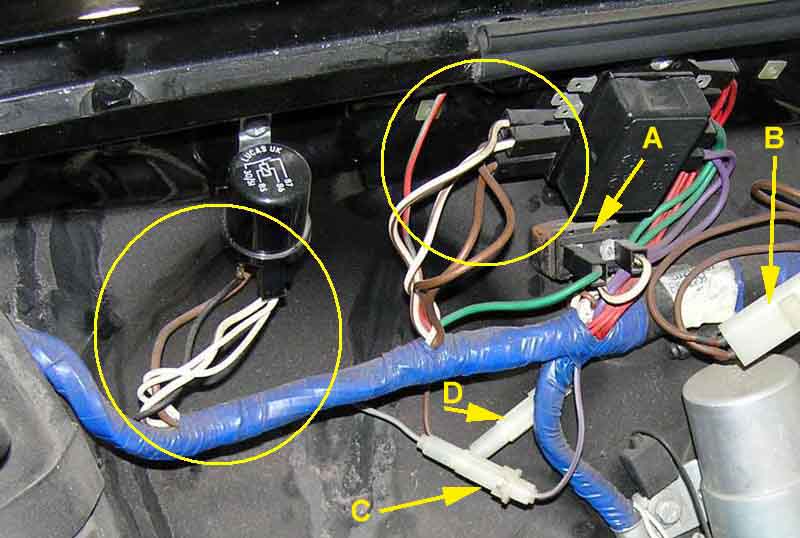
Note 3: 1977 models with the ignition relay can suffer from a problem whereby the engine may continue to run normally (not Dieseling) when the ignition is switched off see here. For 1978 on the problem was corrected by moving the white/brown feed for the ignition coil circuits from the fusebox to the white at the ignition relay, leaving two at the fusebox and three wires at the relay. This also shows 'A' the thermal cut-out for the cooling fans; 'B' the 'double-brown up from the alternator; 'C' the anti-runon valve in-line fuse; and 'D' the hazard flasher in-line fuse:
Note 3: The schematics show the original rectangular Lucas relays with W1, W2, C1 and C2 terminal numbering, but in practice cylindrical relays with ISO numbering were fitted. The relationship is as follows:
| Wire colour | Original numbering | ISO numbering |
| White from ignition switch | W1 | 85 |
| Black earth | W2 | 86 |
| Brown 12v supply | C2 | 30 |
| White/brown to ignition powered circuits | C1 | 87 |