
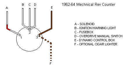
 With the key inserted and turned to the first position (ignition) terminals 3 (brown) and 2 (white) are connected together.
When turned to the 2nd position (start) all three terminals are connected together.
With the key turned fully left or out of the lock all of the terminals are isolated.
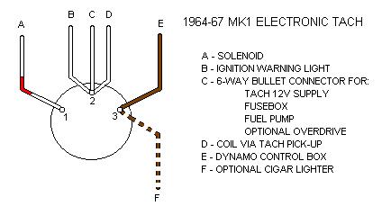 With the key inserted and turned to the first position (ignition) terminals 3 (brown) and 2 (white) are connected together.
When turned to the 2nd position (start) all three terminals are connected together.
With the key turned fully left or out of the lock all of the terminals are isolated.
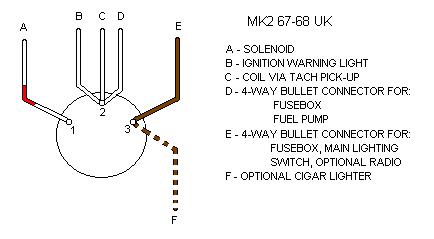 With the key inserted and turned to the first position (ignition) terminals 3 (brown) and 2 (white) are connected together.
When turned to the 2nd position (start) all three terminals are connected together.
With the key turned fully left or out of the lock all of the terminals are isolated.
Note: The Parts Catalogue indicates that MkII cars had the later 13H926 ignition switch with the 4th 'AUX' terminal, but the schematics don't show this being used until the 1969 model year.
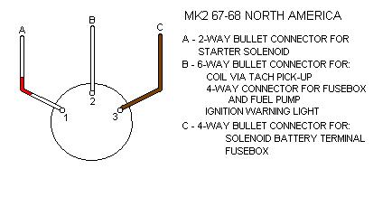 With the key inserted and turned to the first position (ignition) terminals 3 (brown) and 2 (white) are connected together.
When turned to the 2nd position (start) all three terminals are connected together.
With the key turned fully left or out of the lock all of the terminals are isolated.
Note: The Parts Catalogue indicates that MkII cars had the later 13H926 ignition switch with the 4th 'AUX' terminal, but the schematics don't show this being used until the 1970 model year.
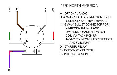
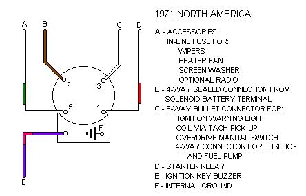
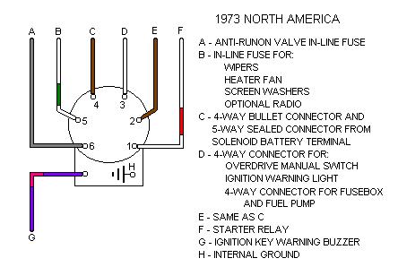
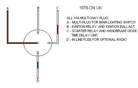
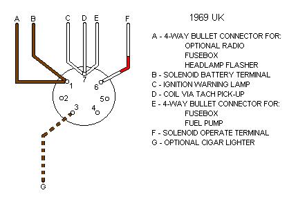 With the key inserted and turned to the first position (accessories) terminals 1 (brown) and 3 (dealer wired colour can vary) are connected together.
When turned to the 2nd position (ignition) terminals 1 3 and 7 (white) are connected together.
When turned to the 3rd position (start) terminals 1, 7 and 6 (white/red) are connected together and terminal 3 is isolated.
With the key turned fully left or out of the lock all of the terminals are isolated.
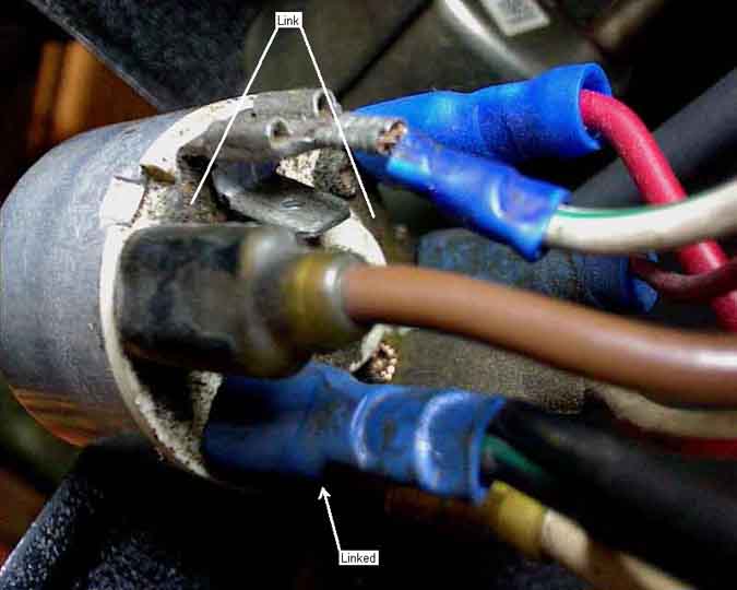
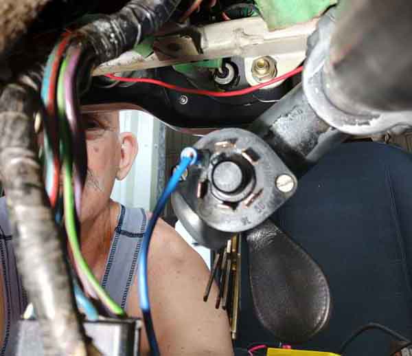
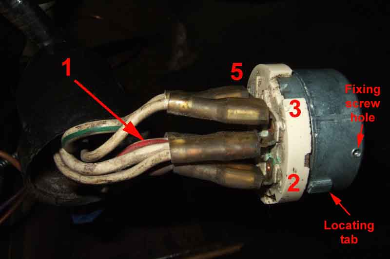
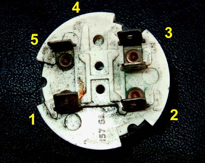
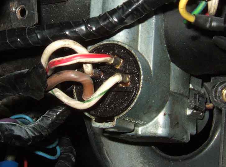
However whilst the diagram indicates there are seven electrical connections to the switch, a look at a switch will show that several of these are paired giving just the four electrical connections that one would expect. The picture below shows the brown and the next spade (non-factory wiring) being paired, then the next two terminals are paired (again non-standard accessory wiring), then the white/brown for the starter is on its own, then the last two are paired for white ignition wires (non-standard wires on the second of these). (Photo Peter Mayo)
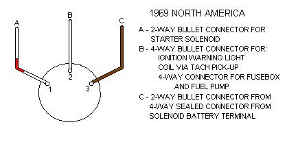 With the key inserted and turned to the first position (ignition) terminals 3 (brown) and 2 (white) are connected together.
When turned to the 2nd position (start) all three terminals are connected together.
With the key turned fully left or out of the lock all of the terminals are isolated.
Note: The Parts Catalogue indicates that MkII cars had the later 13H926 ignition switch with the 4th 'AUX' terminal, but the schematics don't show this being used until the 1970 model year.
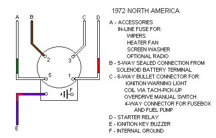
 With the key inserted and turned to the first position (accessories) terminals 1 (brown) and 3 (dealer wired colour can vary) are connected together.
When turned to the 2nd position (ignition) terminals 1, 3 and 7 (white) are connected together.
When turned to the 3rd position (start) terminals 1, 7 and 6 (white/red) are connected together and terminal 3 is isolated.
With the key turned fully left or out of the lock all of the terminals are isolated.
Again refer to the photo above for the physical arrangement.
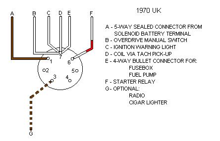
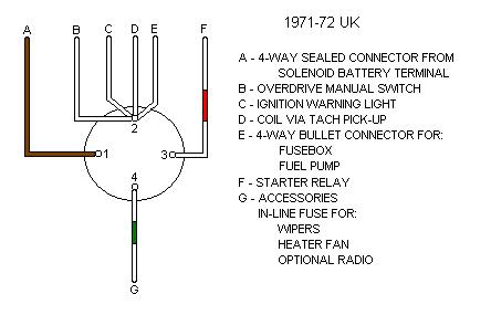
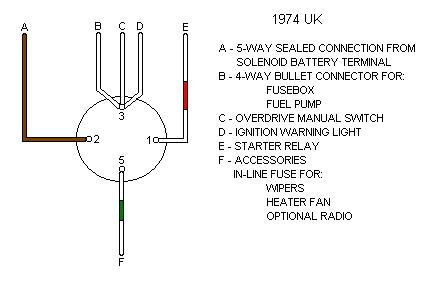
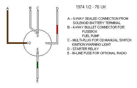
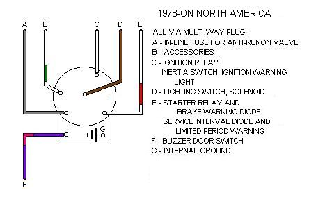
 With the key turned to the first position (accessories) terminals 2 (brown) and 5 (white/green) are connected together.
When turned to the 2nd position (ignition) terminals 2, 5 and 3 (white) are connected together.
When turned to the 3rd position (start) terminals 2, 3 and 1 (white/red) are connected together and terminal 5 is isolated.
With the key turned fully left or out of the lock terminals 1, 2, 3 and 5 are isolated.
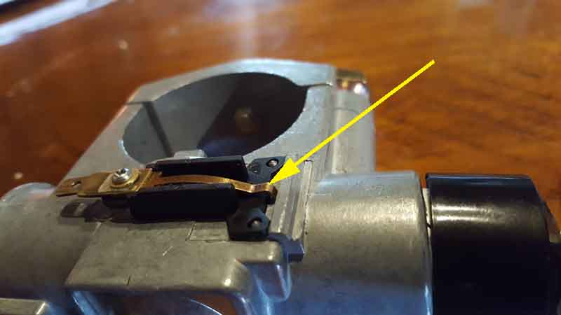
Showing the additional contact for the purple/pink wire - E. When the key is inserted a pin pushes the spring (arrowed) against the body of the lock to connect an earth to the wire, which if the driver's door is opened sounds the warning buzzer. Testing has shown that this only happens when the switch is in the 'OFF' position, however one would expect that it should also be operated in the accessories position. On the face of it, it doesn't need to be operated if the engine is running (should be obvious ...), but that still leaves the situation of no warning buzzer if the engine has stalled and the ignition is still switched on. (Arthur Johnson, restoring a 1972 ex-California GT in Australia)
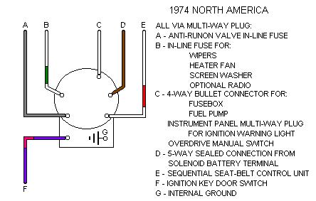
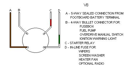
 With the key inserted and turned to the first position (accessories) terminals 1 (brown) and 4 (white/green) are connected together.
When turned to the 2nd position (ignition) terminals 1, 4 and 2 (white) are connected together.
When turned to the 3rd position (start) terminals 1, 2 and 3 (white/red) are connected together and terminal 4 is isolated.
With the key turned fully left or out of the lock all of the terminals are isolated.
May 2015: Note that this numbering may not be correct. The white wires are shown going to terminal 2 - four wires on two spade connectors. But one example of a switch from a 72 has terminals 1, 2, 3 and 4 with linked spades (which will be for the two connectors on the four white wires) on terminal 3. 73 and later schematics show the white wires on terminal 3, which would be correct for this switch, but the white/green for 73 and later is on terminal 5 and there is no terminal 4.
 With the key turned to the first position (accessories) terminals 2 (brown) and 5 (white/green) are connected together.
When turned to the 2nd position (ignition) terminals 2, 5 and 3 (white) are connected together.
When turned to the 3rd position (start) terminals 2, 3 and 1 (white/red) are connected together and terminal 5 is isolated.
With the key turned fully left or out of the lock terminals 1, 2, 3 and 5 are isolated.
For the purple/pink see 1970 North America above.
 With the key inserted and turned to the first position (accessories) terminals 2 (brown) and 5 (white/green) are connected together.
When turned to the 2nd position (ignition) terminals 2, 5 and 3 (white) are connected together.
When turned to the 3rd position (start) terminals 2, 3 and 1 (white/red) are connected together and terminal 5 is isolated.
With the key turned fully left or out of the lock all of the terminals are isolated.
Note there is a number '4' moulded into the switch but this is for an unused space between 3 and 5.
Ceramic-base type:
There are also 'paxolin'-based types with the same terminals and numbering, and others with double spades on two or more of the terminals.
On this model at least more than one spade is used for the white wires, and I found one of those swapped over with the green/white accessories wire. Fortunately it was only the wire feeding the OD, had it been one of the others either the ignition warning light would have been on when switched to accessories, or even worse the ignition, fuel pump and all the green circuits would have been powered. Even so it meant the OD solenoid would have been powered had I left it in 3rd or 4th with the manual switch on, which is not a good thing. As I'd had the car nearly 30 years by then, it had probably been like it since new.
See also this alternative
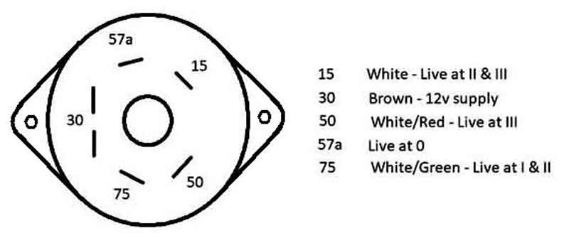
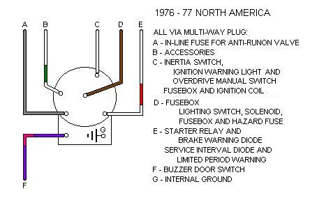
 With the key turned to the first position (accessories) terminals 4 or 2 and 5 (white/green) are connected together, and terminals 4 or 2 and 6 (slate or grey) are connected together.
When turned to the 2nd position (ignition) terminals 4 or 2, 5 and 3 (white) are connected together, and terminal 6 is isolated.
When turned to the 3rd position (start) terminals 4 or 2, 3 and 1 (white/red) are connected together and terminals 5 and 6 are isolated.
With the key turned fully left or out of the lock terminals 1, 3 and 5 are isolated, and terminals 4 or 2 and 6 are connected together.
For the purple/pink see 1970 North America above.
 With the key inserted and turned to the first position (accessories) terminals 2 (brown) and 5 (white/green) are connected together.
When turned to the 2nd position (ignition) terminals 2, 5 and 3 (white) are connected together.
When turned to the 3rd position (start) terminals 2, 3 and 1 (white/red) are connected together and terminal 5 is isolated.
With the key turned fully left or out of the lock all of the terminals are isolated.
See also this alternative
 My wiring diagrams do not show terminal numbers for this lock.
With the key turned to the first position (accessories) the brown (12v), white/green (accessories) and slate or grey (anti-runon valve) wires should be connected together.
When turned to the 2nd position (ignition) the brown, white/green and white (ignition) wires should be connected together and the slate or grey wire should be isolated.
When turned to the 3rd position (start) the brown, white and white/red (starter) wires should be connected together and the white/green and slate or grey wires should be isolated.
With the key turned fully left or out of the lock the white, white/green and white/red wires should be isolated and the brown and slate or grey wires should be connected together.
For the purple/pink see 1970 North America above.
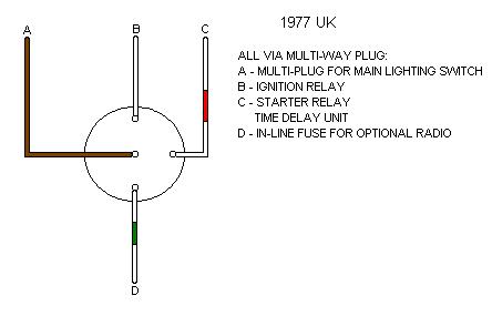
 With the key inserted and turned to the first position (accessories) terminals 2 (brown) and 5 (white/green) are connected together.
When turned to the 2nd position (ignition) terminals 2, 5 and 3 (white) are connected together.
When turned to the 3rd position (start) terminals 2, 3 and 1 (white/red) are connected together and terminal 5 is isolated.
With the key turned fully left or out of the lock all of the terminals are isolated.
Note that UK cars seem to have an extra grey wire on the ignition switch that does not have a matching wire in the main harness.
Note also that replacement switches for UK cars have an extra purple/pink as well as the extra grey wire. These are the same switches as used for North America from 1973 on. They should be plug compatible with UK harnesses, but check the four main wires - brown, white/green, white and white/red match up correctly in both halves of the connector.
 My wiring diagrams do not show terminal numbers for this lock.
With the key turned to the first position (accessories) the brown (12v), white/green (accessories) and slate or grey (anti-runon valve) wires should be connected together.
When turned to the 2nd position (ignition) the brown, white/green and white (ignition) wires should be connected together and the slate or grey wire should be isolated.
When turned to the 3rd position (start) the brown, white and white/red (starter) wires should be connected together and the white/green and slate or grey wires should be isolated.
With the key turned fully left or out of the lock the white, white/green and white/red wires should be isolated and the brown and slate or grey wires should be connected together.
For the purple/pink see 1970 North America above.
 My wiring diagrams do not show terminal numbers for this lock.
With the key inserted and turned to the first position (accessories) the brown (12v) and white/green (accessories) wires should be connected together.
When turned to the 2nd position (ignition) the brown, white/green and white (ignition) wires should be connected together.
When turned to the 3rd position (start) the brown, white and white/red (starter) wires should be connected together and the white/green wire should be isolated.
With the key turned fully left or out of the lock all of the terminals are isolated.
Note that UK cars seem to have an extra grey wire on the ignition switch that does not have a matching wire in the main harness.
Note also that replacement switches for UK cars have an extra purple/pink as well as the extra grey wire. These are the same switches as used for North America from 1973 on. They should be plug compatible with UK harnesses, but check the four main wires - brown, white/green, white and white/red match up correctly in both halves of the connector.
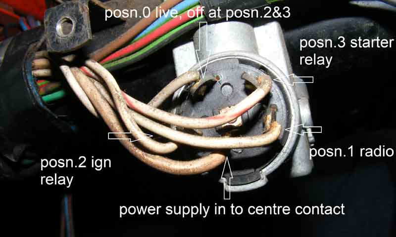
Image from Crispin Allen showing the North American slate/grey anti-runon valve wire at 'posn.0' on a UK 1977:
 My wiring diagrams do not show terminal numbers for this lock.
With the key inserted and turned to the first position (accessories) the brown (12v) and white/green (accessories) wires should be connected together.
When turned to the 2nd position (ignition) the brown, white/green and white (ignition) wires should be connected together.
When turned to the 3rd position (start) the brown, white and white/red (starter) wires should be connected together and the white/green wire should be isolated.
With the key turned fully left or out of the lock all of the terminals are isolated.
Note that UK cars seem to have an extra grey wire on the ignition switch that does not have a matching wire in the main harness.
Note also that replacement switches for UK cars have an extra purple/pink as well as the extra grey wire. These are the same switches as used for North America from 1973 on. They should be plug compatible with UK harnesses, but check the four main wires - brown, white/green, white and white/red match up correctly in both halves of the connector.
 My wiring diagrams do not show terminal numbers for this lock.
With the key turned to the first position (accessories) the brown (12v), white/green (accessories) and slate or grey (anti-runon valve) wires should be connected together.
When turned to the 2nd position (ignition) the brown, white/green and white (ignition) wires should be connected together and the slate or grey wire should be isolated.
When turned to the 3rd position (start) the brown, white and white/red (starter) wires should be connected together and the white/green and slate or grey wires should be isolated.
With the key turned fully left or out of the lock the white, white/green and white/red wires should be isolated and the brown and slate or grey wires should be connected together.
For the purple/pink see 1970 North America above.
 My wiring diagrams do not show terminal numbers for this lock.
With the key inserted and turned to the first position (accessories) the brown (12v) and white/green (accessories) wires should be connected together.
When turned to the 2nd position (ignition) the brown, white/green and white (ignition) wires should be connected together.
When turned to the 3rd position (start) the brown, white and white/red (starter) wires should be connected together and the white/green wire should be isolated.
With the key turned fully left or out of the lock all of the terminals are isolated.
As you can see this switch comes with a short sub-harness and bullet connections to connect to the main harness:
Most Cars Built before 1 January 1985 are Exempt From VED
Drivers for Hire Making Tax Digital MTD Compatible Software