
As explained on the main page the original voltage stabiliser seems anything but as it actually turns system voltage on and off once or twice per second. But the length of the 'on' pulse varies with system voltage - shorter as voltage rises - while the length of the 'off' pulse remains the same, and the effect is to create an 'average' (over a couple of pulses) of about 10v. The gauges also being thermally operated are slow acting so do not respond to the pulses (although if you look very closely you might see very small movements).
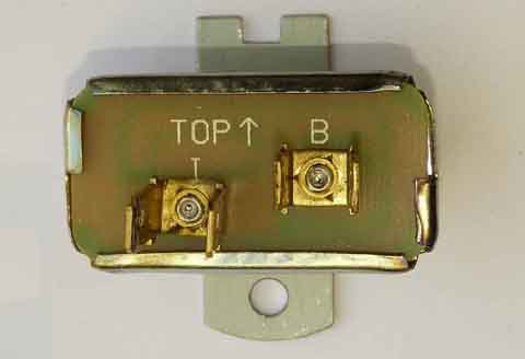
A Mk1 stabiliser, all male spades, and no calibration screw. Green goes to the B(attery) terminal and light-green/green to the I(nstruments) terminal. The E terminal goes to a case rivet and hence earth through the mounting tab. Note the stabiliser needs to be mounted above the fixing screw:
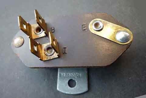
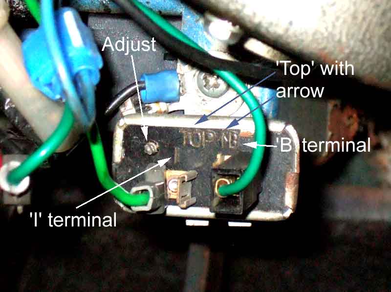
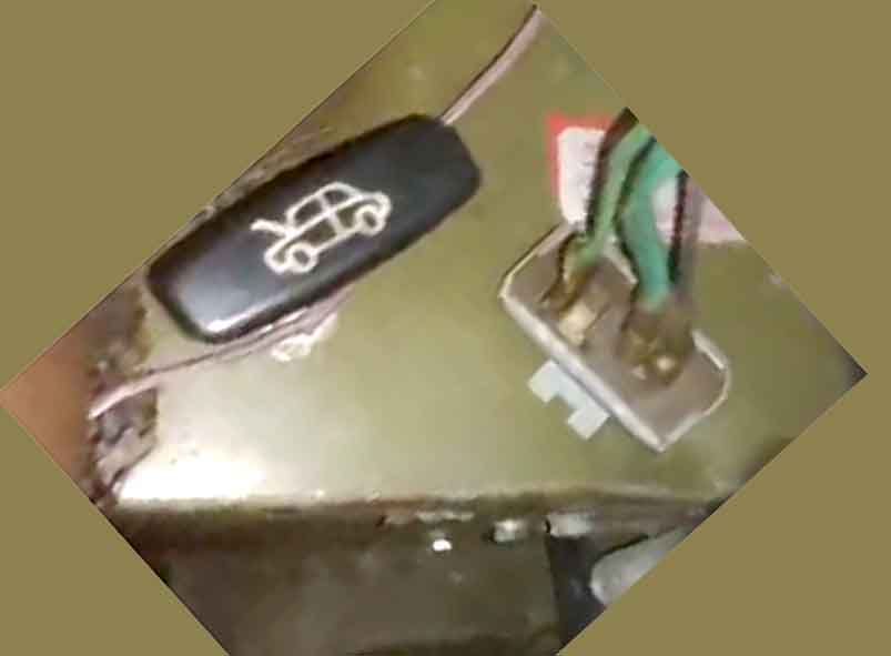
An original Mk2 thermal voltage stabiliser, with the adjuster stud. Note the 'I' ('Instrument') terminal has female spades and needs a male spade on the end of the light-green/green wire. The 'B' terminal ('Battery') has a conventional male spade on the stabiliser, and hence a female spade on the green wire. Note just to be different this stabiliser is mounted below the fixing screw:
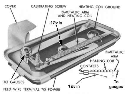
What lies inside, from Bob Skelly:
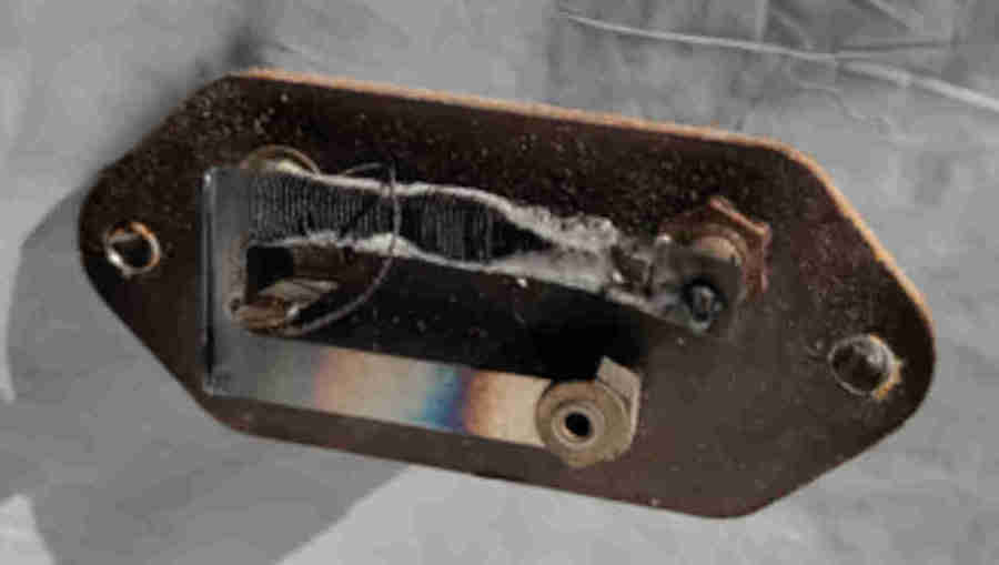
And Edgar Deighton, showing the disposition of the internals when mounted correctly:
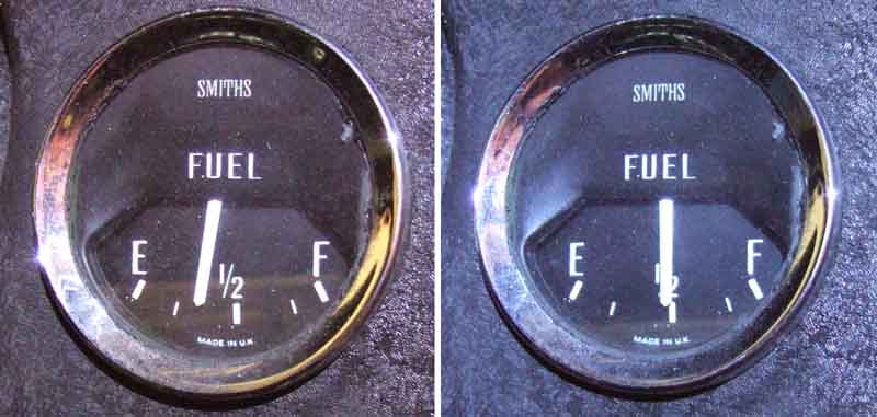
How significant is the mounting orientation? Quite a lot! Ever the enquiring mind, I test Vee's both right way up (left) and upside down (right) and found a surprisingly large difference in gauge reading:
But thinking about it, the U-shaped strip is all bi-metal, so that both halves bend an equal amount to compensate for different ambient temperatures, and only the half with the heating coil bends further when powered to open the contacts. With the heating coil in the lower of the two positions then heat from the coil will rise and tend to affect the other half, whereas if it's above it will not (other than warming all the air inside the can, which being metal, and screwed to body-work, will tend to act as a heat-sink). If the heating coil is having an effect on the unheated side then it will tend to cancel out the main heating effect, which will delay the opening of the contacts, and so give a higher gauge reading. That being the case the heated side is probably at the top, along with the adjuster screw, and that is confirmed by the photo of the Mk2 version further up the page.
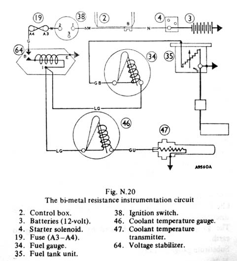
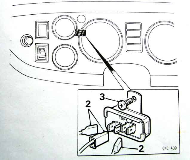
Drawing from the Leyland Workshop Manual, with errors. As shown, with the contacts open at '64', the gauges would never work as there is no path for 12v to pass through to them and the senders. The contacts should be drawn closed. Also the colour of the wire(s) from stabiliser to gauges is light-green with a green stripe, i.e. 'LGG', and not 'LG' a shown:
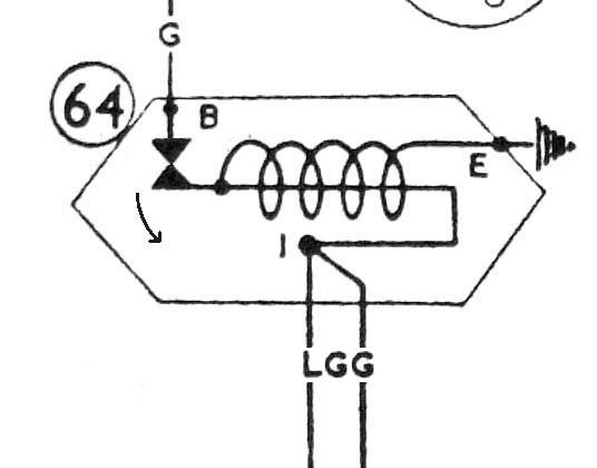
Drawing corrected, with arrow, showing direction of movement of the contact on the bi-metal strip:
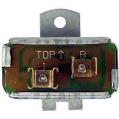
An electronic version compatible with the Mk1 wiring, and mounted above the fixing screw. This still has the 'Top' and arrow markings, but the printed circuitry can seen through the insulating piece the spades are mounted on. No calibration screw:
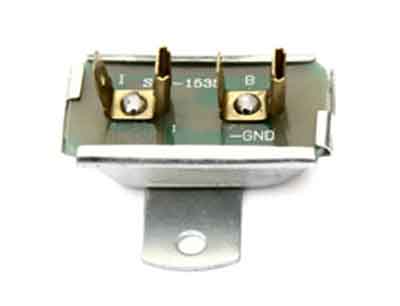
An electronic version compatible with Mk2 wiring, and mounted below the fixing screw. Still with 'TOP' and arrow markings, but the printed circuitry even clearer. Again no calibration screw:
Yet another version from some sources, this time with one male and one female spade on each terminal. As there only ever seems to be two wires going to the stabiliser, hence only one spade on each terminal is used, I suppose this could be classed as a 'universal' replacement as it will be compatible with both Mk1 and Mk2 wiring:
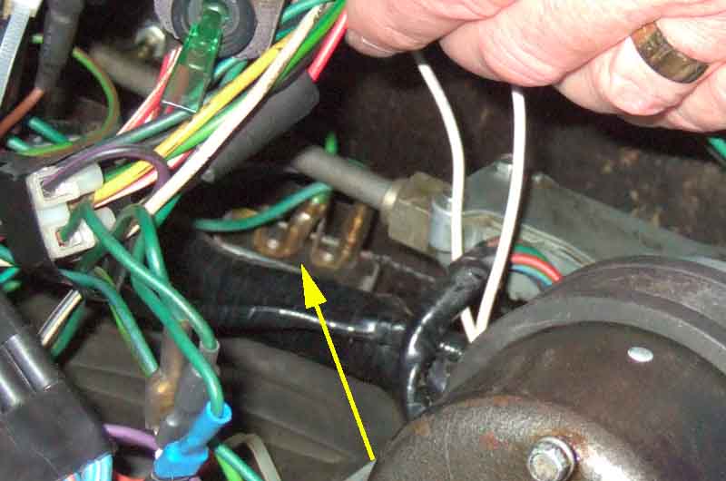
On my 73 roadster the stabiliser is positioned high up on the bulkhead, behind where the wiper rack exits from the motor - not very accessible:
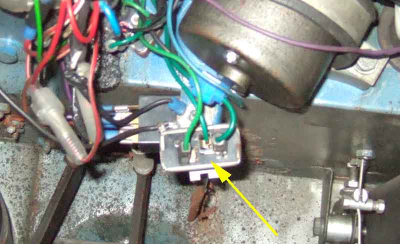
On later models (this is my 75 V8) it is positioned on the lower edge of the bulkhead and much more accessible:
On this 76 North American LHD it is quite accessible - incidentally the original thermal type should be mounted horizontally and not at an angle as this is (the random wire goes to the left-hand door switch, it was always a single wire each side, not wrapped): (Bill Etter)
Maybe less so on 1977 and later: (Leyland Workshop Manual 1977)
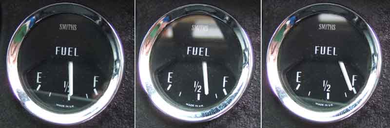
Demonstrating a faulty stabiliser: Working normally on the left; faulty with ignition on engine not running in the middle; faulty with engine running (make sure you blip the throttle so the alternator is charging) on the right - a significant difference. The gauge should read the same with the ignition on regardless of whether the engine is running or not:
Showing how the original 'thermal' voltage stabiliser outputs full ignition voltage when the ignition is first turned on, for about 15 seconds, then starts pulsing on and off to average about 10v. However this cannot be read using a simple digital voltmeter. By contrast an analogue meter 'damps' the needle movements so that the average voltage can be read easily:
By contrast a replacement electronic stabiliser outputs 10v immediately the ignition is turned on, but has the drawback that the fuel gauge (for example) takes longer to reach a steady reading.