Hover over a wire to confirm the colour
Prior to 1971 the Workshop Manual shows North American cars having an optional courtesy light controlled by door switches and an integral manual switch, as well as a map light. But according to Clausager all North American Mk2 cars prior to 1971 had a map light on the centre console controlled by a rocker switch below the radio, not getting the courtesy light until the 1971 model year. The WSM also indicates the earth to the manual switch in that courtesy light as coming from its mechanical fixings, but being mounted on a plastic console it would have to be a wired earth.
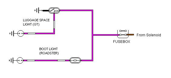
The standard circuit as used from 1971 (North America) or 1972 (elsewhere):

Note: Haynes issue dated 2010 with coloured schematics has an error in the drawing of the courtesy light for 1973 cars, and later - they have reversed the 12v (purple) and earth (black) connections, putting 12v to the switch and earth to the bulb. Wired that way it wouldn't work at all from either the door switches or the manual switch, but if both are operated at the same it will blow the purple circuit fuse. Earlier versions e.g. my 1989 copy are drawn correctly.
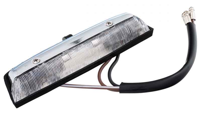
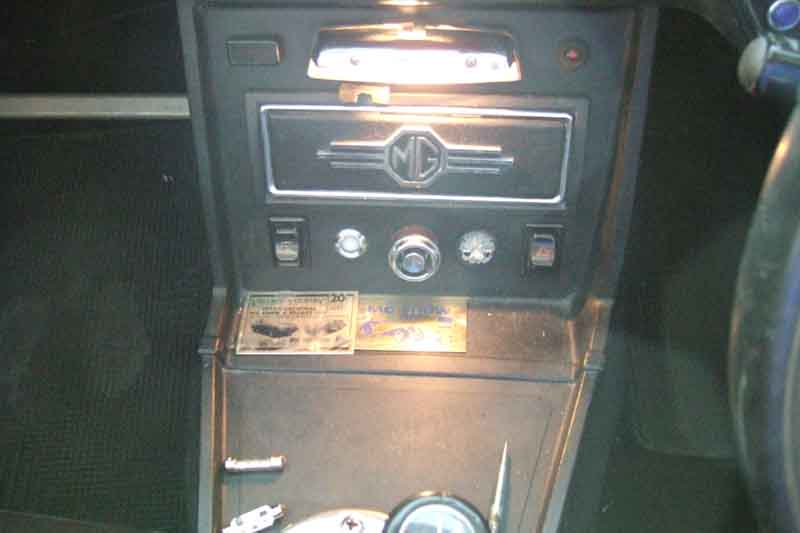
Centre console light BHA5138: (Moss Europe)
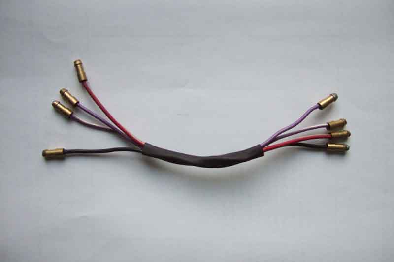
An extender harness for the purple (fused 12v), black (earth), purple/white (courtesy switch earth) and red/white (illumination) wires behind the centre console. That still has to be fitted to the main harness as a one-off exercise, but once that's done things like the courtesy light, lighter socket etc. will be easier to deal with in future:
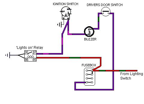
With 'lights on' warning buzzer:

This has been redrawn and rewritten as the previous version still allowed for a drain. Only discovered when helping a pal look for a drain - found to be through the buzzer diode. I then looked at the circuit to compare his with how I thought it should be wired, and immediately realised the circuit was wrong, and had been for over 15 years! Hopefully right now ... unless anyone knows different.
Diode 1 is essential to prevent a continual small drain from the courtesy light circuit, through the buzzer and to earth via the parking lights while the car is parked with the lights off. This option is provided by connecting the positive end of diode 1 into the spare hole of the 4-way bullet connector that is behind the centre of the dash.
Diode 2 can be added to prevent the passenger door and the manual switch on the courtesy light also sounding the buzzer. To avoid cutting wires this version can be provided by taking the drivers door switch wire out of the 4-way bullet connector behind the centre of the dash, and making up a 3-way tee with diode 1 and the buzzer to the parking light circuit; diode 2 to the 4-way bullet connector; and a wire via a new 2-way bullet connector to the drivers door switch wire.
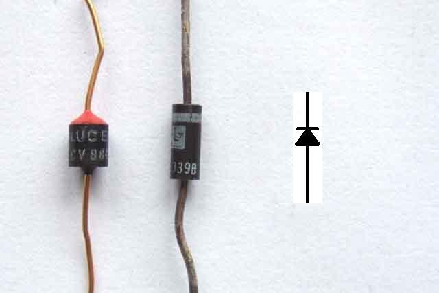
Diode polarity is shown for negative earth cars, reverse for positive earth..
Diodes showing how the markings relate to the schematic symbol, i.e. the marked end (red blob, thick silver band) denotes the pointed end of the 'arrow' symbol, and the direction of the arrow indicates the direction of conventional current flow i.e. from +ve to -ve. Note the one on the left is a Lucas (yes, that Lucas) diode, the other is the type you are more likely to find these days:
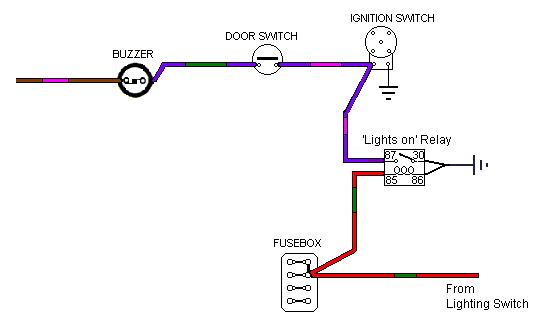
North American spec cars with Seat-belt Buzzer:
In all cases add the relay with connections to the purple/pink and red/green circuits as shown. The relay simulates the key being left in when you open the door, i.e. sounds the buzzer, but from the lights being left on instead. The key-in function is unaffected, if either the lights are on or the key is in when the drivers door is opened, the buzzer will sound.
1971-73 driver and passenger seat-belt warning system
1973-75 driver and passenger seat-belt warning system with starter interlock, and 75-80 driver only systems.
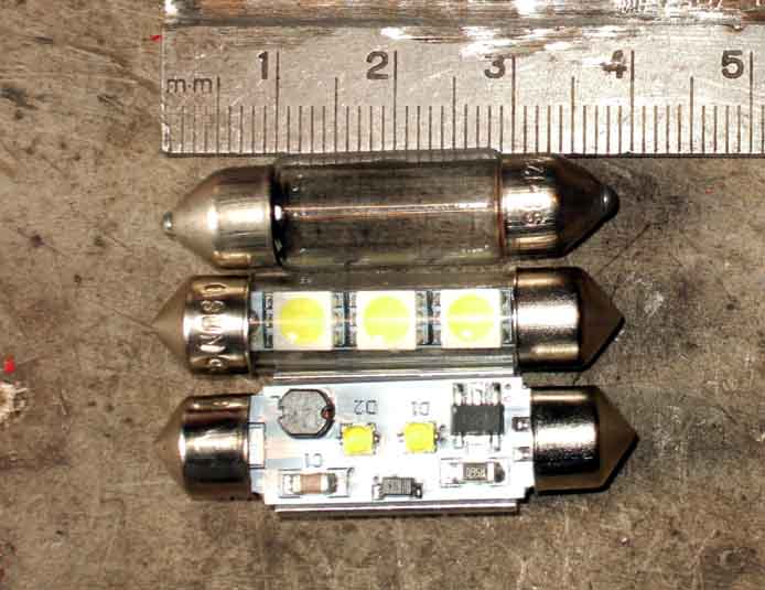
From top to bottom an original 6w type; commonly available '5050'-type; less commonly available Cree type. There are several different lengths of festoon available (reverse light festoons are 44mm for example), whilst the holders can be 'adjusted' for a range of sizes opt for the standard 39mm for courtesy lights.
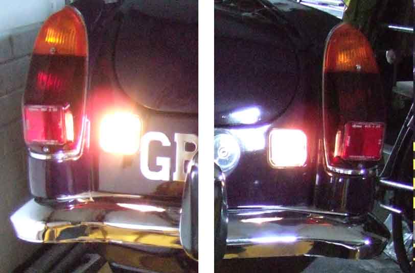
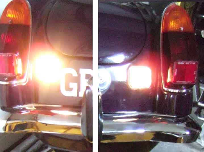
In the reversing lights for comparison - both sides taken in the same picture then edited together for convenience. Standard 18w festoons on both sides, despite the one on the left appearing brighter, possibly a newer bulb with less blackening inside the glass.
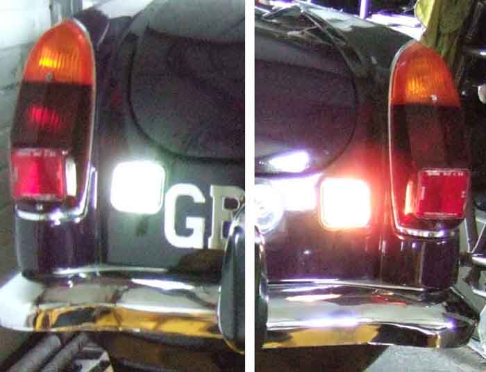
Standard 18w festoon on the left, noticeably brighter than the 6w on the right
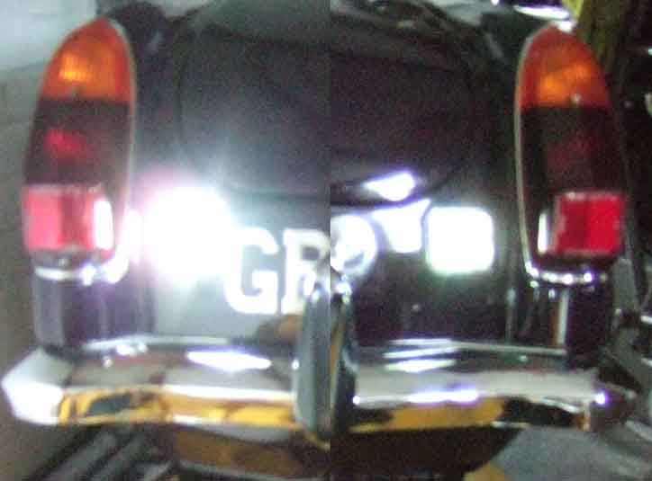
5050-type on the left, 6w festoon on the right - not obviously brighter, just whiter
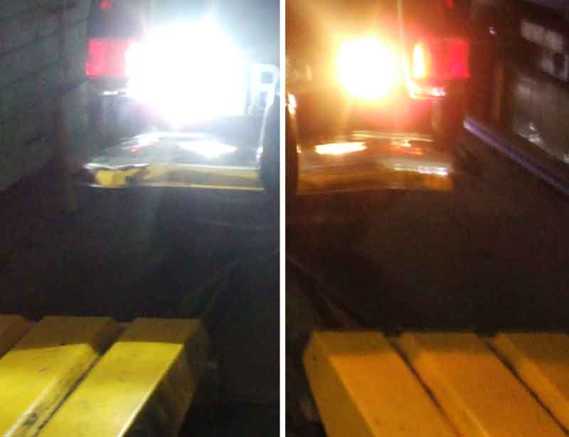
Cree-type on the left - very much brighter than the standard 18w festoon on the right
Finally Cree-type on the left - again much brighter than the 5050-type on the right
More difficult to compare the three in the interior light fitting as I can only take one at a time - standard 6w festoon.
5050-type - almost identical exposure as shown by the foot brace and floor mat patterning in the passenger footwell, hence equivalent brightness, albeit whiter of course.
Cree-type: Much less exposure, sharper contrast, much less detail in the passenger footwell, showing it is much brighter.
'Eagle Eye' light
The LED positioned in the cut-out for the latch release, on the right-hand side so as not to interfere with the release mechanism in either the locked or unlocked positions. Attached using a strip of plastic (from an offcut of square black guttering downpipe - very useful stuff) under one of the latch fixing screws. It could be attached using a screw or double-sided sticky pad to the underside of the latch, but I have my emergency boot release mechanism already there.
The cable is run down inside the reinforcing frame towards the right-hand hinge, then up into the cavity in the boot surround, to the switch and boot harness bullet connector for the switched earth and 12v supply respectively. A cable tie round the frame near the hinge keeps it in position. I've removed the existing boot light and its sub-harness making connection of the new light easier - just two bullets on the end of the cable - as it no longer serves a useful purpose, and the cover was always falling off anyway.
GT loadspace light
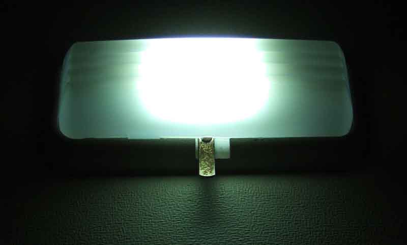
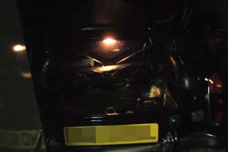
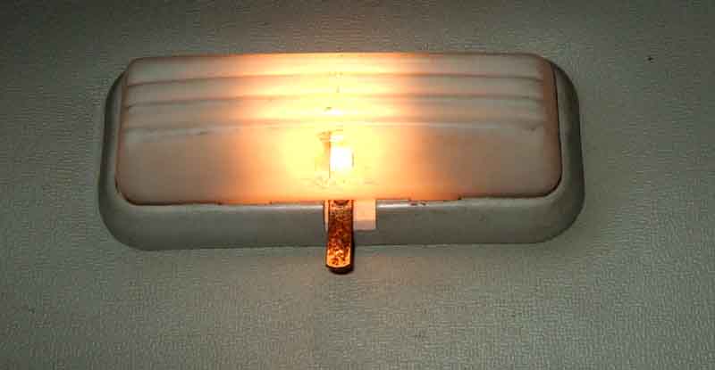
The original incandescent festoons can damage the cover (and that on the interior lights) through heat - the bright patch just above the switch is a hole in the cover (24G3389). Annoyingly although I have replaced the roadster boot light with an LED the undamaged cover from that will not fit the GT as even though the bases of both light units are flat, and the edges of the GT cover are also flat, the edges of the roadster cover are curved!
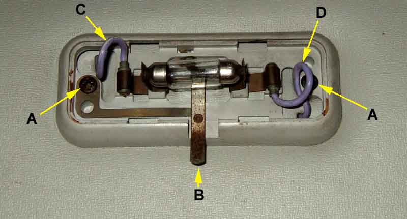
'A' are the fixing screws, the left-hand one (in this image, right-hand on the car) picks up the earth for the manual switch from the car body.
'B' is the manual switch.
'C' is the purple/white wire from the hatch switch.
'D' is the purple 12v supply wire.
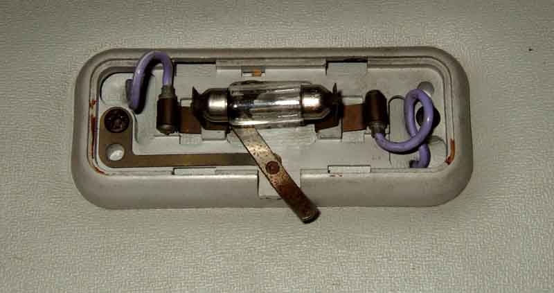
Manual switch operated, simply touches the left-hand (in this image, right-hand on the car) bulb contact. The purple/white wire from the hatch switch must go to this end of the courtesy light and the purple 12v supply to the other end. Getting them the wrong way round will blow the fuse:
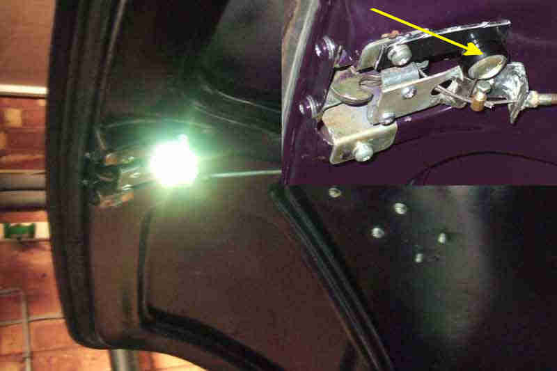
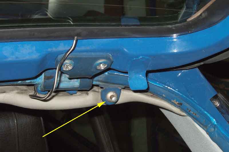
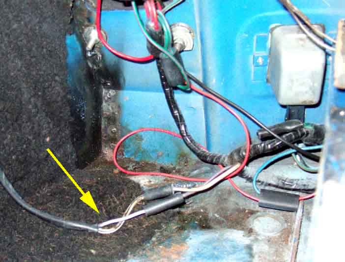
The manual switch (arrowed), depressed by the tab on the hatch to turn the light off.
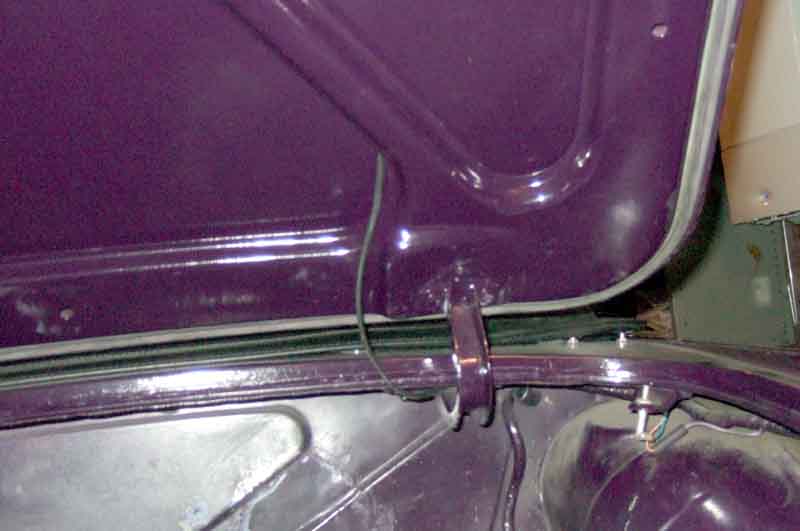
The 12v feeds to the load-space light (purple) and HRW (white/black) come off bullet connections by the right-hand light cluster and go up the C-post.
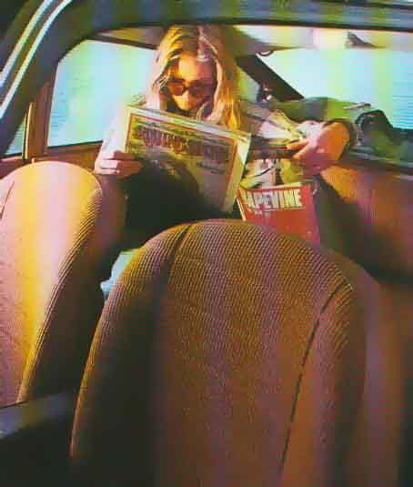
Why a manual switch? Perhaps ... (from an original sales brochure). It should be noted that the only way someone of typical adult stature can sit in the back is if their head is craned forwards ... hence the magazine.
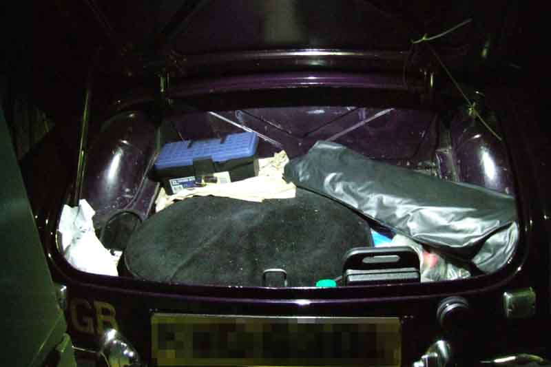
With new cover and an LED, it's the big increase in brightness that has reduced the exposure.