Engine Mounts
Rubber bumper and V8
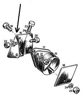
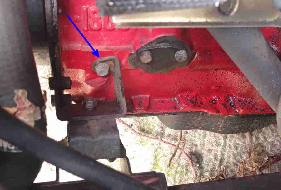
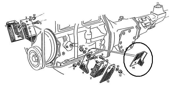
The chrome bumper control bracket (circled). The flange on the back of the bracket will contact the chassis bracket after a small amount of forward movement of the engine, preventing any further movement of the fan towards the radiator. Incidentally the two bolts that attach the mounting bracket to the engine front plate on the left-hand (carb) side, numbered 6 here, are countersunk, and there are corresponding recesses in the bracket itself. Logically this would be to prevent the heads of standard bolts rubbing against the rubber, but the two bolts on the right-hand (alternator) side are hex-head bolts. All four nuts are stiff-nuts, used with spring washers, whereas all the other nuts on the engine mounts are plain. Also note the optional spacer plate (13) which - when fitted - is always on the carb side. Image from Moss Europe
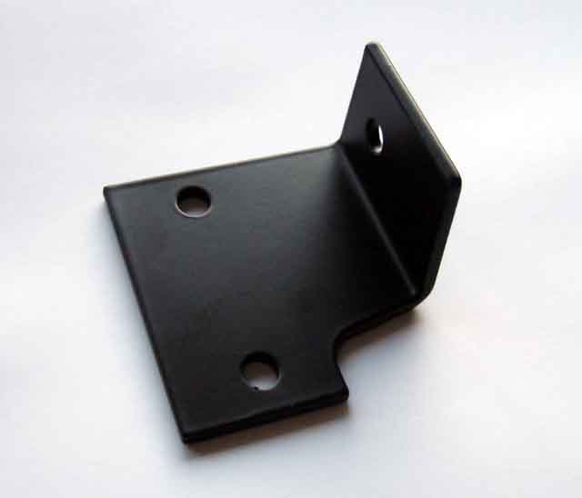
Chrome bumper restraint bracket AHH7890, one of three types listed in the Parts Catalogue this is the only on available and is suitable for all chrome bumper cars. Spot the subtle difference to the drawing above! The two holes on the left go behind the bracket attached to the engine front plate, on the mount studs. The hole in the flange is a bit of a mystery, it can be used to mount the carb vent/overflow pipes P-clip with a nut and bolt (although the correct place for it with HS carbs is to a bracket (NLA) mounted on a stud or under a bolt screwed into the block where the mechanical fuel pump goes on non-MG applications). Interestingly the image above shows the early non-positive vent pipe being clipped to the rear-most of two bolts through the blanking plate for the mechanical pump. I'd wondered why the bracket for the vent/overflow pipes was such a complicated shape, instead of the clip being held by one of the bolts directly as on rubber bumper cars. The bracket was obviously designed to fit round this early breather, which was only used until 1964, after that the clip could have attached directly to that rear bolt!
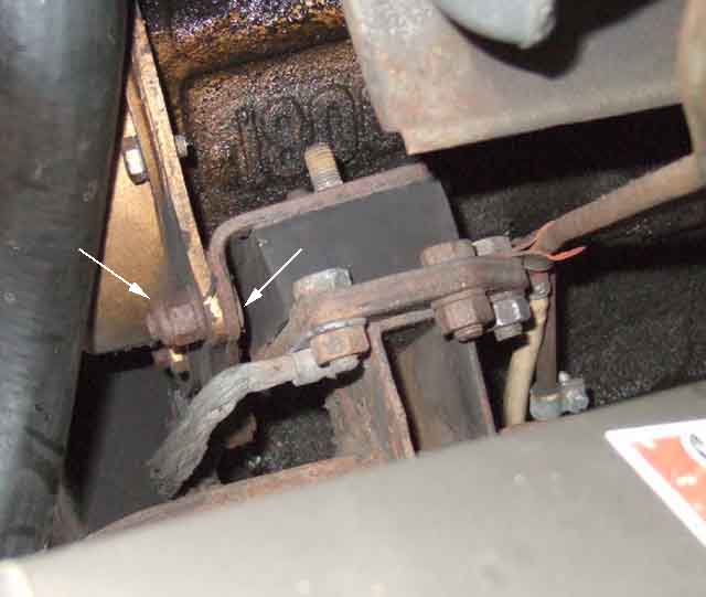
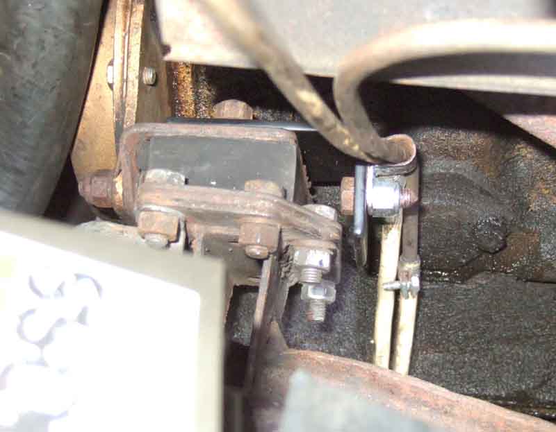
Vent/overflow pipes attached to the chassis side of the mount as I'd seen on a concourse winner (also shows the countersunk bolts and stiff-nuts, arrowed) ...
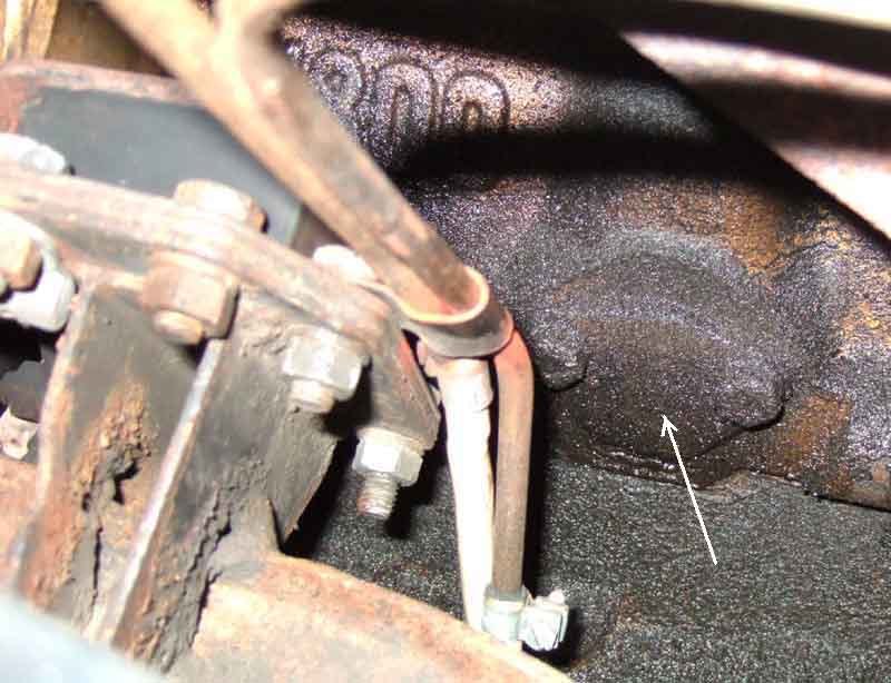
... so moving the pipes on their hoses as the engine rocked. Also shows the mechanical fuel pump blanking plate (arrowed), used for mounting the original crankcase pipe and carb pipe bracket. It's possible that the P-clip for the overflow pipes should go under the head of one of the blanking plate bolts.
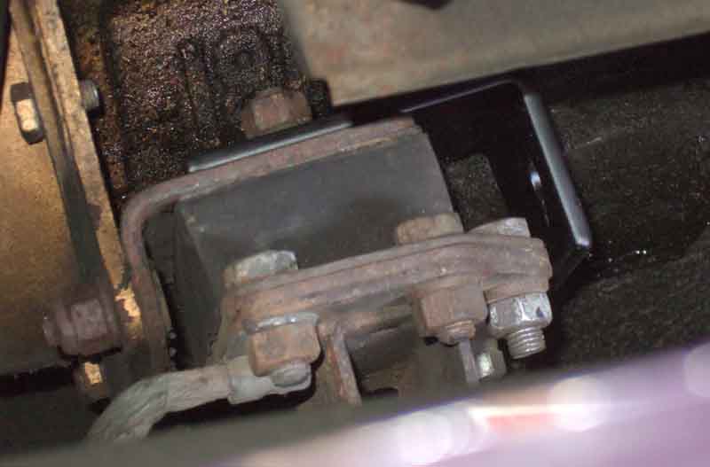
Restraint bracket mounted ...
... limiting the forward movement of the engine to about 1/4", with the carb pipes attached to it using the convenient hole so they move with the engine. I opted for this point rather than a pump blanking plate bolt, as they proved pretty tight working from above and I didn't want to risk starting an oil leak (OK it looks oily already but it doesn't drip).
Rubber bumper
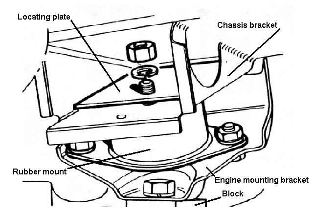
Looking up into the chassis bracket from below. The locating plate is fitted so that the hole is in the lower of the two possible positions, to ensure the mount stud is near the bottom of the chassis bracket slot. (Drawings of a V8 but the same principle must be applied to 4-cylinder cars).
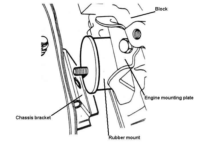
The chassis bracket from above. There must be sufficient spacers to prevent the stud lying in the bottom of the slot, but not so many that the locating plate cannot be fitted the correct way round. It's not indicated in the drawing, but this must be the near-side of a V8. The visible cross-member nut is slightly forwards of the chassis bracket, and the mounting plate is installed with its flat side towards the rear, and its angled side towards the front.
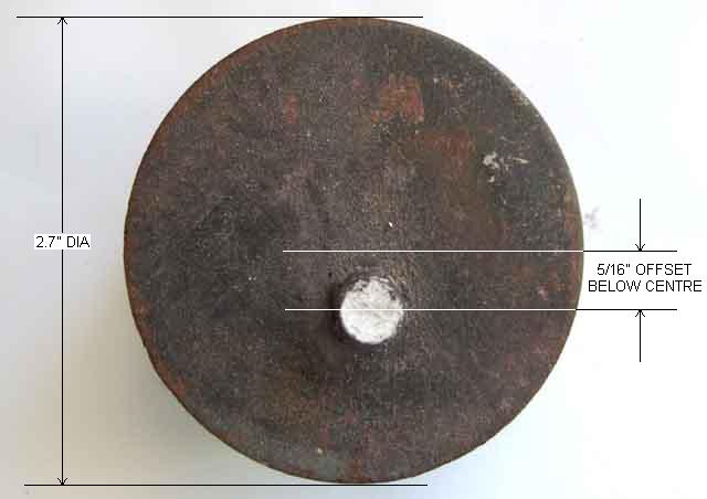
Dimensions for fabricating a spacer (applicable to V8 right-hand side)
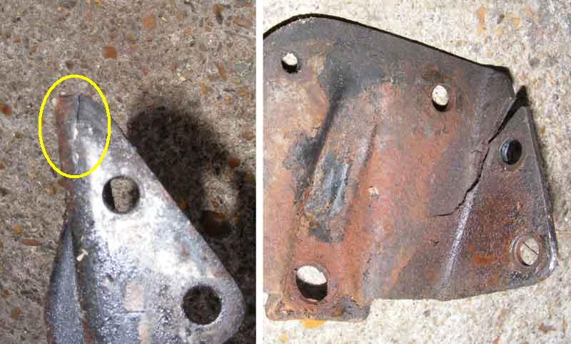
Showing the common point of fracture on left-hand 4-cylinder rubber bumper brackets (arrowed), also the correct orientation of the rubber mount 15 and locating plate 18: (Moss Europe)
However Crispin Allen found both of his cracked, with the driver's side (on the right here) much worse than the passengers:
As well as the bolts to the front plate there should also be a third bolt to the block, not easy to see on the MGB but clearly visible here on a Marina, make sure they are fitted:
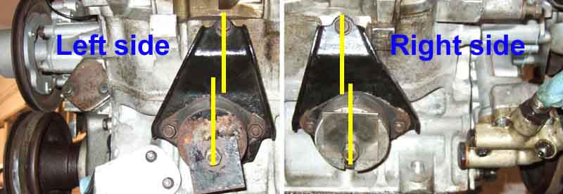
V8 mount bracket orientation: The upper bolt securing the bracket to the block must be behind the stud on the mount that goes into the chassis bracket, putting the engine in the rear-most of the two possible positions:
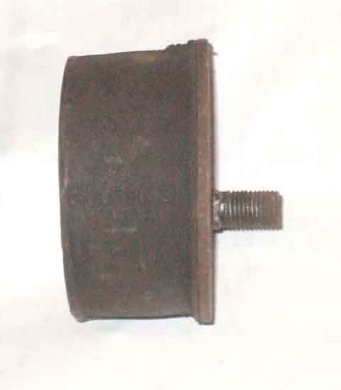
Showing the stud in the lower of the two possible positions when attached to the crankcase bracket. Note this is an old mount where the 'eared' or oval back-plate of the mount has been ripped off.