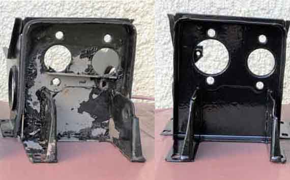
Single-circuit and unboosted dual:
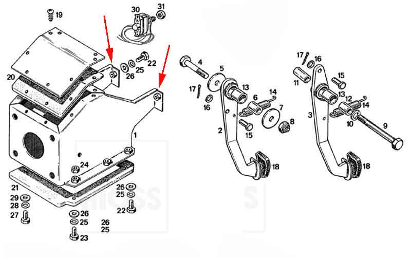
Item 15 'bush, pedal' AAA4129 is for both pedals (was NLA in October 2016, shown as available from several suppliers in January 2017). Item 6 'bearing tube' is the pivot bush AHH7201, again the same for both pedals. 11 is the two spacer washers PWZ206, and 10 the distance tube AHH6063 that fits between the two spacer washers. The pivot bolt bushes are slightly wider than the pedals, so that when the bolt and nut are tightened the two pivot bolt bushes, spacer washers and distance tube are clamped up between the sides of the pedal box, which leaves the pedals free to rotate on the pivot bolt bushes with minimal sideways movement and 'wobble': (Moss Europe)
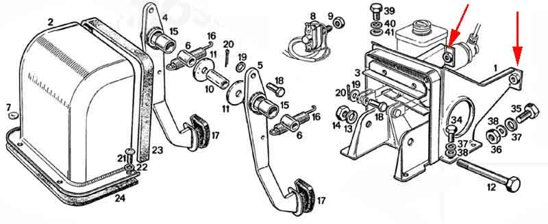
October 20918: However there is an oddity in the screws that attach the pedal box to the heater shelf. The Parts Catalogue doesn't explicitly identify these, but under item 8 - 'AHH 8421 (for example), Box - master cylinder there are six HZS405 (1/4" x 5/8" UNF, 7/16" head, item 37 below), one HZS407 (1.4" x 7/8" UNF), seven PWZ104 (1/4" plain washers) and seven LWZ204 (1/4" spring washers). You could be forgiven for thinking that the six HZS405 would be for the pedal box, but you are wrong. The middle one on the brake pedal side is actually 5/16" x 5/8" UNF (1/2" head, item 38 below), which is listed next in the Parts Catalogue i.e. HZS505 together with 5/16" plain and spring washers. I discovered this on the roadster when looking underneath the shelf for an attachment point for a mechanical brake light switch, and noticed this welded nut is noticeably larger than the other five. Wondering if it was a one-off I checked the V8 and it is the same. The only thing I can think of is that they opted for a bigger screw beside the brake pedal, as there is going to be a lot more force applied to that pedal than the clutch pedal. Still odd they didn't do it both sides though. Along the way I discovered that one was not fitted to the V8, I must have tried to use a 1/4" when putting things back after the repaint in 2017, discovered it wouldn't fit, and somehow it got left. As I need to fit a longer one to the roadster for said brake light switch bracket I transferred that one over. Initially I thought I would have to remove the pedal cover, but there is just enough room between that and the wing flange to get a 3/8" drive socket and extension bar in.
Incidentally the upper pedal box securing bolts (arrowed in red above and below) are a pig to remove as the bolts go through from the cabin side, and you have to go up behind the dash behind all the wiring to get at them. The inboard one is even worse as it has the steering column supports (later column as on Vee at least) below it as well. Removing it for Vee's (75 V8) repaint I got to the outboard one with two 3/8" drive wobble extensions, but the inboard could only be accessed with a ratchet-ring spanner. Initially I only had three very fine clicks of movement, which would have taken forever (even when loose I couldn't get my slim fingers to it) but by removing the relays and voltage stabiliser, and the indicator flasher and its clip, I got about 15 degrees of swing. Still took patience though.
July 2022: Steve Long has a 74 UK roadster and writes:
The pedal arrangement labelled with the item numbers in the above drawing, only the pedal (15) and pivot (6) bushes are hidden. With this arrangement everything except the pedal and its bush (for obvious reasons) should be clamped up tight:
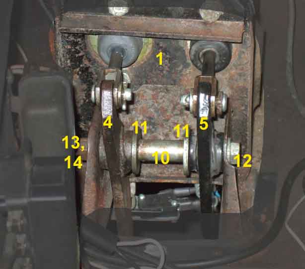
When gripping the distance tube 10 you should NOT be able to rotate it ...
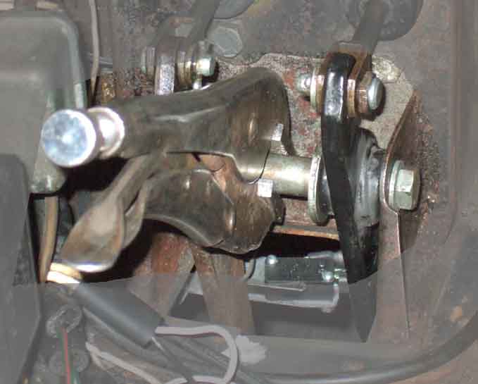
... nor the spacer washers 11. If you can it's not clamped up as it should be. If clamping it prevents the pedals moving then either the pedal bush (15) is too wide or the pivot bush (6) is too narrow. If 10 and 11 are clamped up tight but the pedal still wobbles excessively then either or both of the pedal or pivot bushes are worn where they contact each other:
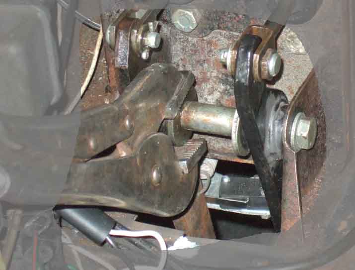
Although the original pivot was a bolt with most of its length as plain shank replacements are threaded for their full length i.e. technically a screw, and more than once people have said this leads to pedal slop as the bushes wear on the threads. But that shouldn't happen if everything has been installed correctly as the pivot bushes should be clamped up tight in the frame along with the spacer washers and distance tube so cannot rotate on the screw thread although this information has fallen on deaf ears. The only movement anywhere should be the pedal pushes on the pivot bushes as they are slightly shorter so not clamped up with everything else.
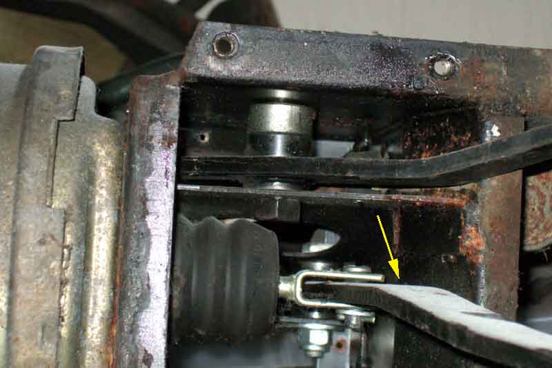
View from the top. The clutch pedal clevis and split pin are relatively easy to remove - not as easy as the earlier system though. This also shows that the clutch master upper bolt comes through from the back with a washer and nut inside the pedal box:

The brake clevis and split pin are buried and can only be accessed from below - nigh-on impossible with the pedal box installed. Also because the pivot is above the servo push-rod the brake pedal cannot be removed from either above or below as the pivot and the pedal pad are both wider than the fork of the push-rod, which extends almost to the back face of the pedal box. The servo has to be unbolted from the pedal box, and that can only be done with the whole kit and caboodle removed from the car:

View from underneath of a removed pedal box showing the clutch pedal (at the top, brake pedal below) with spacer. What appears to be penny-washers under the pedal and above the spacer are reflections. The arrow indicates where the hole for the brake light switch is on this pedal box, behind the brake pedal, which moves forwards (to the left in this image) and away from the switch as the pedal is operated:
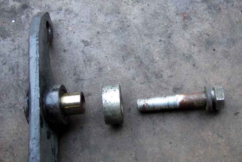
Clutch pedal with the distance tube (pivot bolt bush) flush with the pedal on the left, protruding on the right. The spacer sits on the distance tube with the pedal. The bolt head has a spring-washer. These original bolts do have a plain section below the head, which current replacements may not have, and the distance tube is initially a sloppy fit on the threads. However the distance tube is slightly wider than the pedal plus the spacer, so once the bolt is tightened the distance tube is clamped between the sides of the box, so the clearance between it and the pivot bolt threads is irrelevant:
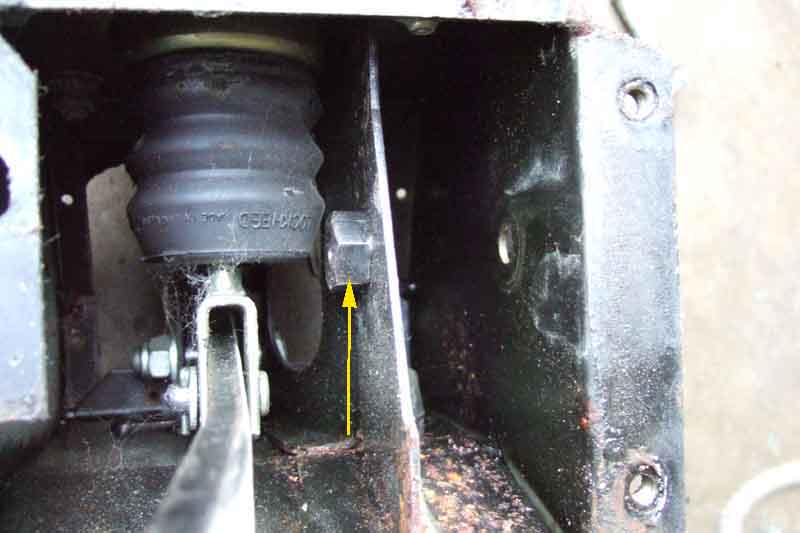
The clutch pivot nut (arrowed) is welded to the box. Tightening the bolt clamps the distance tube (pivot bolt bush) into the box leaving the pedal and the spacer free to rotate but with minimal sideways movement and 'wobble':
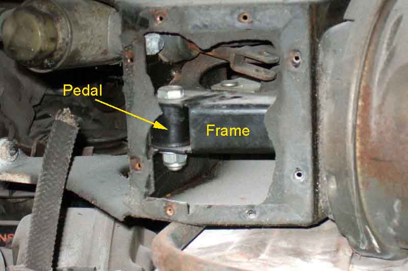
The brake pedal pivot is even simpler. The distance tube is fractionally wider than the pedal and its bush, and is clamped into the box by the bolt and nut, leaving the pedal free to pivot with minimal sideways movement and 'wobble':
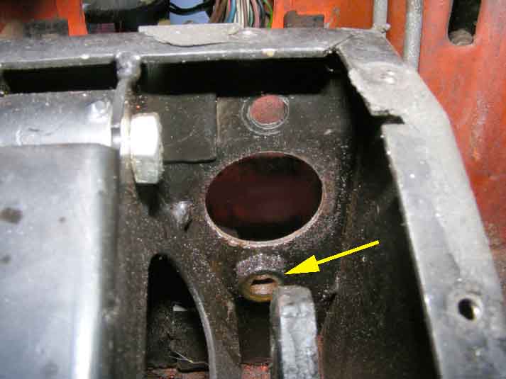
This view shows that the lower clutch master cylinder nut (arrowed) is welded to the inside of the frame, and therefore that the bolt goes in from the back of the master. Pictures above show the upper bolt also coming in from the back but with a washer and nut: (Crispin Allen)
