
Pal Terry is reassembling his third MGB and the fuel pump doesn't work. Not surprising as it is an abandoned restoration. He tried cleaning the points to no avail, so posted it up to me. I immediately found it had some physical damage at the electrical end - broken spade, a punctured end-cap and a broken pedestal where the stud carrying the 12v spade is mounted. He has another spare pump that is also dead, so asked me if I could build up one good one out of his two and posted that up to me as well.
I swapped the good pedestal and spade into the first pump, cleaned the points and tested it, but pumping wasn't very strong. Blocking the output left the pump ticking about once per second instead of once every 30 secs or less, and fuel was draining out of the clear pickup pipe when power was disconnected. So I opened up both pumps and found the first one was pretty oxidised inside, whereas the second was much cleaner. The diaphragm on the first pump was also damaged - it consists of two layers of cloth-reinforced rubber with a thin 'plastic' membrane on the fuel side - but the membrane was split allowing fuel to be in contact with the rubber. So I ended up putting the second spade, pedestal, pump chamber, diaphragm and end-cap on the first pumps solenoid! That gave much better pumping results and was duly posted back to Terry. He had no immediate use for the other pump and said I could keep it, so I said I'd get a repair kit, keep it as a second spare (I already have a Moprod) and he would have first call on it.
I contacted Burlen to ask about pedestals, but they were most unhelpful. Kept trying to sell me a repair kit, which doesn't contain the pedestal! Dave Dubois gave me the part number, and Googling that showed a number of suppliers. They had various combinations of the parts I needed but none had all, and in the end I decided to get the repair kit, pedestal, spade and end cap from Burlen, who do have all the parts on their web site if you are patient enough to search for them by part number.
First thing was to assemble the new points to the new pedestal. In the past on pumps I have worked on the pin has been a loose fit in both so an easy job. But this pin was a tight fit, and had to be pushed in through the outer frame then the pedestal leg while being gripped with pliers. But it's not easy doing that while holding the moving contact inner frame exactly in line with the hole, and it's almost exactly the same width as the gap it has to fit in. But I managed to push the pin through just a fraction, so I could locate the hole in the contact frame over the very end of the pin, then push the pin further through. I could see immediately that the upper and lower fingers on the outer frame were way out of adjustment, and only allowed for a small amount of movement, but decided to leave that until later when the pedestal was on the solenoid body giving me something firm to grip. The contact frame is supposed to be free on the pin, but this was quite stiff to begin with. But flipping it back and fore with the pedestal off the end of the solenoid freed it up.
There are three possible quenching devices on MGB pumps (earlier pumps had no quenching at all):
SU Burlen state that these pumps take 1.5 amps at the minimum voltage of 9.5v, which implies a solenoid resistance of 6.3 ohms. However when I measure the resistance between the two pump spades of mine I see about 2 ohms, which implies a current of 6 amps at 12v, and 7 amps at a running voltage of 14v. I then measured the current through the solenoid i.e. bypassing the points and at 12v saw 5.5 amps - so where do Burlen get their 1.5 amps from? If you power a pump on the bench, not pumping fuel i.e. chattering away, using either an analogue meter or a digital meter that will average the current, that's when you will see about 1.5 amps. In other words the current that Burlen quote is the average of the current flowing while the points are opening and closing, and they are open for longer than they are closed. So if you intend to fuse your pump don't be tempted to use the minimum rating of, say, 2 amps, as the fuse will probably eventually fail. I've never seen any reason to use other than the standard 15 amp rated, 35 amp blow fuses, as they are designed to protect the wiring and the pump wiring is no thinner than other fused circuits, and you have (or should have) two spares in the fusebox already. Start fitting blade types, or different ratings, and you have to carry more spares. Ok, that's no great hardship, but it isn't necessary either.
The original diaphragm consisted of a double-layer of cloth reinforced rubber, plus a thin 'plastic' membrane that was in contact with the fuel. The new diaphragm only has a single layer of reinforced rubber, and no plastic membrane. So not only is it less than half the thickness, but the rubber is now in contact with the fuel which is wasn't before. So what that means in terms of longevity of the diaphragm, and its resistance to increasing levels of ethanol in the near future, can only be wondered at. Also with half the thickness of rubber the gasket becomes even more important at taking up any distortion in the two flanges i.e. the solenoid body and the pump chamber body. The former is cast so pretty robust, but the latter is alloy which can be distorted by the action of the screws clamping the two together. So I ran a flat carborundum stone around the flange of the pump chamber, to find that the edges were indeed slightly bowed out between the screw holes, and spent some time reducing this as best I could. Another thing to wonder at is how flexible the 'one-piece' diaphragm is compared to the old. I used the edge of the old one to bend down the edge of the new one, and see which bent more. Both bent by the same amount, indicating the stiffness of the new one-piece is much the same as the original.
There have been at least three methods of correctly locating the back of the diaphragm with the recess at the end of the solenoid. The oldest was eleven brass spacers which are quite fiddly to fit. They were replaced by five 'figure of eight' plastic spacers which are easier to deal with, and that was replaced by a one-piece plastic guide plate (Dave Dubois) that effectively joins four figure of eights together which is much easier to fit. Oddly the repair kit came with the individual brass spacers, even though the included instructions show and discuss the one-piece guide plate. As dismantled the pump had the five 'figure of eights', so I reused those.
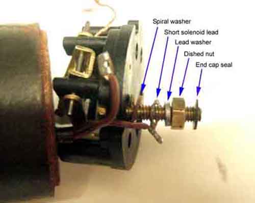 The brass threaded bolt with the hex head that carries the input spade then has to be pushed through from underneath the top part of the pedestal, a spiral washer fitted, and the shorter of the solenoid wires, before the pedestal can be fitted to the end of the solenoid. The correct order of components is spiral washer, solenoid tag, lead washer, and the dished nut with the dish facing the lead washer. The head of the bolt fits in a recess in the underside of the upper part of the pedestal, and the nut can be loosely tightened.
 The pedestal is fitted to the solenoid with a spiral washer under the head of the screw by the brass stud. The other screw has the braided wire from the moving contact frame fitted first i.e. against the head, then a spiral washer, before being fitted through the pedestal into the solenoid body.
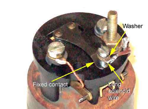 The fixed contact goes against the upper face of the pedestal, with the longer solenoid wire on top of that, then the washer, then the screw. The fixed contact is slotted so can be fitted after the screw with the solenoid wire and washer have been fitted to the pedestal but not tightened, but must go between the solenoid wire and the pedestal. The fixed contact should be adjusted back and fore (utilising the slot), and from side to side, such that it's two contact pips lie directly above the two contacts pips on the moving contact.
 Lifting the moving contact by hand check that, as far as possible, both contact pips are touching at the same time to give even wear, and not favour just one of them. The easiest way to do this is look at the fixed contact just as it starts to be lifted off the rib on the pedestal. If one side appears to start moving before the other, then twist the moving contact frame slightly so that both sides start to lift at the same time.
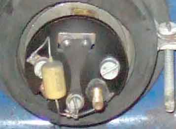 Initially a capacitor that is connected between the screw securing the fixed contact and the screw securing the braided wire from the frame. The capacitor is typically a buff-coloured cylinder with one wire at each end. It's not polarity conscious and can be connected either way round, but if one terminal has a large slotted or holed tag than the other, then the large one goes under the pedestal screw and the smaller one between the solenoid wire and the washer on the fixed contact fixing screw. This means that capacitors are connected across the points.
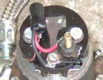 Capacitors were replaced by diode-resistors by the end of MGB production to give superior quenching, on pumps with an AZX designation. These are polarity conscious and the diode-resistor must be connected the right way round to match the polarity of the car. It won't cause damage to the rest of the car if they are connected incorrectly, it probably won't even reduce the effectiveness of the quenching, but the pump will take an extra 1 amp of current. The diode resistor is a black cylinder with two wires at the same end, one with red insulation and one with black. For early positive earth cars the black wire from the diode should go between the solenoid wire and the lead washer on the threaded brass stud, and the red wire between the solenoid wire and the washer on the fixed contact fixing screw. For later negative earth cars the red wire goes on the brass threaded stud, and the black wire with the fixed contact. This means that diode-resistors are connected across the solenoid coil.
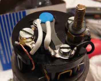
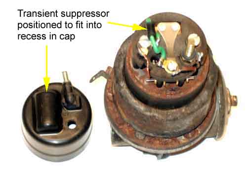
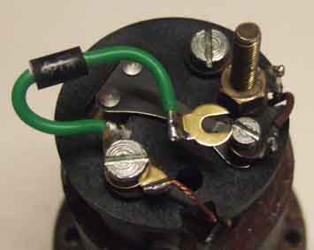 Diode-resistors have now been replaced by a bi-directional transient suppressor, which can be either a flat disc with a wire off each side, one parallel to the other, or a small cylinder with a wire coming away from each end. These are not polarity conscious so can be fitted either way round. However this black one came with a small slotted tag on one end and a larger holed tag on the other. The smaller tag goes between the solenoid wire and the washer on the fixed contact fixing screw, and the larger tag goes with the braided wire tag under the pedestal fixing screw. Note this positioning is only initial fitting, and is not orientated correctly for cap fitting.
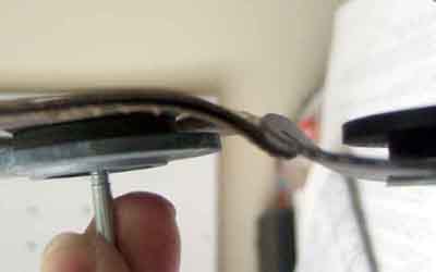
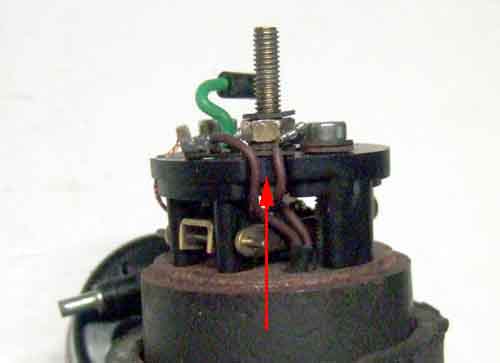 When tightening the dished nut it's important to make sure the tag on the shorter of the two solenoid wires doesn't trap or damage the other solenoid wire in the slot by the brass bolt. As you tighten the nut the tag wants to turn as well, and if left to its own devices it can trap the wire. Even if that doesn't happen the longer wire can end up being pressed against the tag by the end-cap. Use an implement to hold the tag away from the longer wire while you tighten the nut (note the tag is nowhere near the right-hand pedestal screw as it appears here). If the insulation is pierced the solenoid is effectively shorted out, which will damage the wiring all the way back through the rear and main harnesses, and the ignition switch, to the starter solenoid. Both my cars came to me with the wiring damaged in this way, plus two that I have worked on, and whilst writing this article I examined the pump a pal has recently been having trouble with to find obvious heat damage from the same cause. It's why I have fused both my pumps and strongly recommend it.
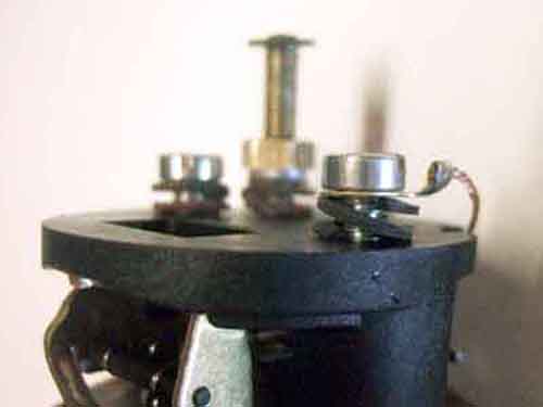
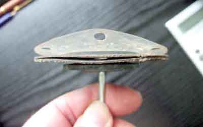
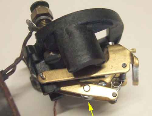 With the trunnion on the moving contact inner frame in the lower of its two stable positions i.e. against the top of the solenoid (shown here before fitting to the solenoid), fit the diaphragm rod up though the middle of the solenoid. Screw the rod into the trunnion, which is easier said than done as the rod wants to push the trunnion away from it, and when it flips up to the back of the pedestal the rod won't reach. You also have to carefully align the trunnion so the threaded hole is in line with the diaphragm rod. Make sure the plastic washer is fitted to the diaphragm rod before the rod is inserted through the solenoid. This is essential to leave an air gap when the solenoid pulls the diaphragm in, without it the diaphragm may not release when the points open to disconnect power from the solenoid.
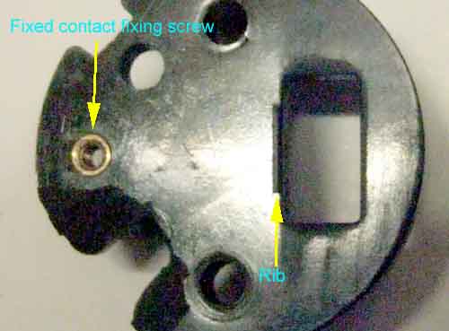
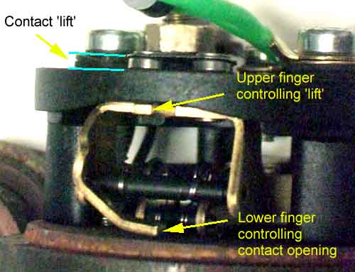 The Burlen instructions mention in step 3 (e) to 'adjust the finger settings', but it's not until step 8 that you are given details of the lift and clearances of the two stop fingers. I have found that you must set the clearance and lift of these before adjusting the diaphragm as described in step 4, as adjusting them afterwards results in a very different diaphragm position. Also it talks about a 'lift' of the fixed contact on top of the pedestal of 35 thou, but shows this value as being between the underside of the spring of the fixed contact, and the pedestal surface. In fact the fixed contact rests against a rib on the pedestal, so is already lifted by a few thou when the moving contact is pulled away from it, making it a clearance rather than a 'lift'.
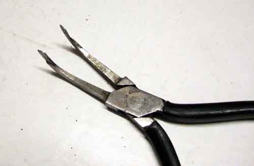 Whilst I was able to use a pair of long-nosed pliers to adjust the bottom finger that rests on the end of the solenoid, to adjust the upper finger where it rests against the bottom of the pedestal I had to use special spring-adjusting pliers which date back to my GPO days. The two clearances are 90 thou for the lower finger and 35 thou for the upper. Both fingers are adjusted with the diaphragm released, and the moving contact lifting the fixed contact off its rib. The lower finger at 90 thou needs specialised feeler gauges which I don't have, so I used a dial gauge and Mk1 eyeball to gauge the gap. For the upper finger whilst I can make up 35 thou with my standard feeler gauges it is with two or more gauges so you have to make sure they are pressed firmly together, by using an implement to press all of them down onto the top of the pedestal whilst sliding it towards the fixed contact. If you don't press them down like that multiple feeler gauges will tend to splay apart and you will get a larger gap than intended. You can't rely on the fixed contact squeezing them together, like you can when checking valve clearances for example, as the splay on the gauges is as likely to lift the fixed contact as anything else. Recheck that both contact pips are touching at the same time, and if the moving contact frame has to be readjusted to achieve that, then recheck the clearances, and repeat until both are correct.
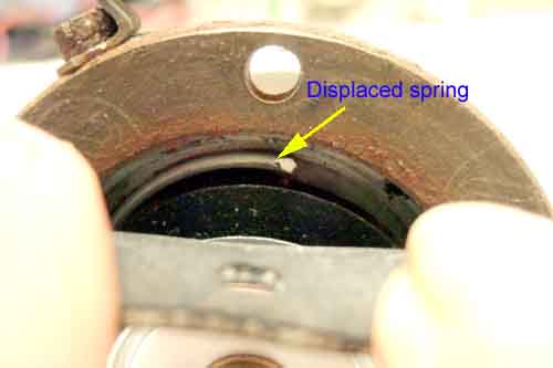 With the gaps set screw the diaphragm into the trunnion until when pressing the diaphragm towards the base of the solenoid firmly, the contacts just fail to throw over i.e. fail to open. With the new diaphragm and spring I found the spring kept getting displaced to one side and preventing the diaphragm going fully back, which would give a grossly incorrect setting. You have to be sure the spring is centralised, and learn how far the diaphragm goes back when it does so fully. The diaphragm and hence points throw is finally adjusted when the two halves of the pump are ready to be brought together.
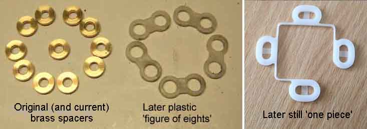
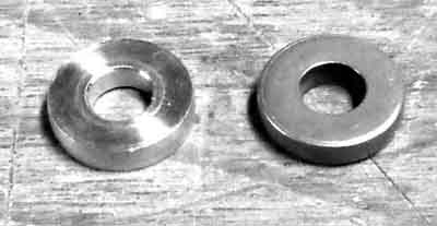 August 2016: Apparently SU Burlen started using the brass spacers again a couple of years ago. Allan Reeling queried this with SU Burlen and they said "The reason we went back to the brass spacers, 11 should be fitted, was that we found that pumps were running cooler with these fitted than the plastic spacers used before". However Dave Dubois who rebuilds pumps says he runs them for an hour and had never noticed any overheating. He does find that the 'figure of eight' type are quite a tight fit and tend to dig into the diaphragm as they have sharp edges. The one-piece type is much looser but because of that can allow the armature to rub against the coil core which makes the pump erratic, and any of those he finds get binned. So the brass spacers are best, but the current ones are just stamped out and have sharp edges which can cut the diaphragm, the originals had at least one face chamfered as in Dave's picture here. Dave keeps and reuses any originals he finds, and 'tumbles' new ones to remove the sharp edges before fitting.
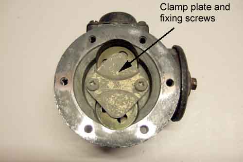
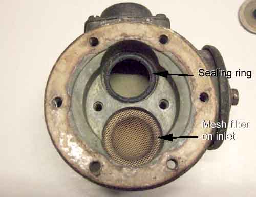
Now you can turn your attention to the pump chamber. As this pump chamber had been leaking back I removed the valve clamping plate and covers to replace both one-way valves.
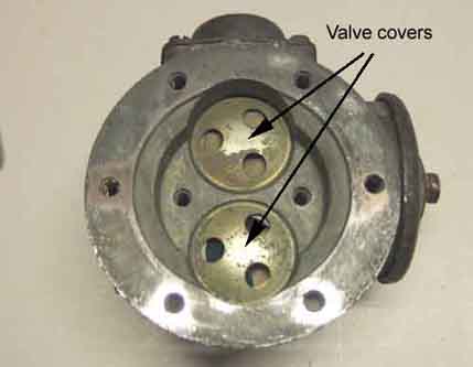
The inlet consists of the valve that sits on a thin rubber sealing ring, which sits on the mesh filter, which sits on another thin sealing ring, which sits in the pump body. The outlet just consists of a valve and a thin rubber sealing ring sitting in the pump body.
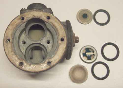 Carefully pick out all the components without damaging the faces in the pump body that the sealing rings sit against. Use a curved implement through the inlet port to push the mesh filter out if required.
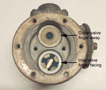
Test the new one-way valves before fitting. Use your mouth to make a seal around the edge of each valve and suck and blow. You should be able to blow air through from the 'plain' side to the 'finger' side, but not the other way. The finger retains the moving part of the valve in the fixed part, but make sure there is a clearance of about 1.6mm or 1/16" under the finger to allow the valve to operate.
The outlet port is by the small external domed chamber and the words 'TOP' and 'OUTLET' cast into the body. Avoiding any dirt or particles, fit a new sealing ring into the outlet port recess in the pump body, and a new one-way valve, with the finger facing downwards into the pump body. In the inlet fit a new sealing ring, the mesh filter with the dome going into the port, another sealing ring, and the other one-way valve this time with the finger facing upwards. Carefully centralise the valves in the recesses so there is an equal gap all the way round, fit the cover plates, and the clamping plate and screws.
There are no components under the large cover with the central fixing bolt, or the smaller cover with the four fixing screws, so I left those alone apart from checking the screws were tight, even though new gaskets etc. are part of the kit. Subsequently a pal did much the same job on his pump and did replace the gaskets, and had terrible trouble with them leaking afterwards. Eventually he had to replace the pump body, it has become apparent that the bodies were changed slightly but the two types are not differentiated and some replacement parts do not fit old bodies very well.
Preparing to reassemble the solenoid and pump chamber: The Leyland Workshop Manual says that with the solenoid separated from the pump body, screw in the diaphragm until the points don't throw over when the diaphragm is pressed up against the base of the solenoid. Ensure the diaphragm return spring is fully seated, if it is dislodged it prevents the diaphragm moving towards the solenoid body as far as it needs to go. Then unscrew bit by bit, pressing the diaphragm against the solenoid body as you go, until they just throw over. Then unscrew to the next hole, then "unscrew it a further quarter of a turn (four holes)". Now this makes no sense as there are six holes around the edge, four holes would be two thirds of a turn, and a quarter turn is 1 and a half holes! Haynes just says "unscrew a further quarter turn". I've always done them two holes as I couldn't be sure exactly what Leyland meant by 'four holes', and a quarter turn isn't possible, so two is between the two. However a pal just found this SU Burlen page which says "unscrew a further four holes (two-thirds of a complete turn)" which makes more sense. So mine are under-adjusted by 50%, but I've never had a problem with fuel delivery, and I'll leave them be until the next time I have to do one.
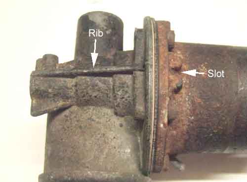 To assemble the solenoid to the pump chamber, look for a square protrusion with a slot on the flange on the solenoid body, and a longer rib facing the flange on the pump chamber. The two halves are fitted together with the rib in line with the slot. Insert the screws and tighten gradually and evenly, again ensuring the diaphragm return spring is fully seated.
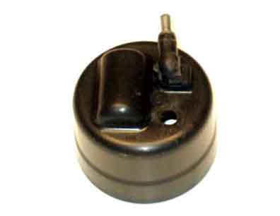
End cap:
 As I mentioned earlier the points pivot in the new pedestal is a tight fit, so the pump could be operated without the end cap fitted. But if the pin is loose as I have found previously it will work its way out of the points and the pedestal is operated with the cap off, so best to refit the cap. The capacitor/diode-resistor/transient suppressor needs to be carefully orientated to fit into the domed or stepped area of the cap, and its leads must be well clear of both the fixed and moving points, partly so it doesn't physically impede them and partly so that the insulation doesn't wear away and cause shorts.
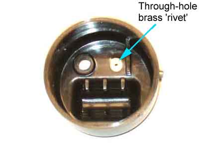
If fitting a new end-cap be aware that the vent port with the one way valve is not supplied with new caps, so the existing one must be recovered from the old cap or a new one purchased. The remove the existing grasp the external part firmly, and pull, and it should come free releasing a small brass through-hole 'rivet' from the inside of the cap. Fit the vent into the new cap, in the stepped hole, not the plain hole (confirm by test-fitting the cap to the pump and see which hole the threaded stud comes through for the cap to properly seat) then push the brass spigot into the port from inside the cap and press home.
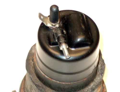 The end cover seal washer - soft rubber or plastic - is fitted over the threaded stud before the end-cap is fitted. Fit the cap. If you have a lock-washer fit that, then the spade terminal, then a plain brass nut. Don't overtighten the nut. But if you have double nuts fit one first but don't overtighten, then fit the spade terminal, and the second nut. The second nut can be tightened down firmly onto the spade and first nut. Finally fit the plastic tubing with the closed end, over the exposed threads of the brass stud.
Testing. Applying power to a pump not plumbed in - observing polarity for diode-resistor quenched pumps - and it should chatter rapidly. Blocking each port in turn with a thumb should slow the chattering slightly, and if you remove the power with outlet port still blocked, then remove your thumb, you should hear/feel a slight release of pressure. Likewise when blocking the inlet port with the power connected, then removing the power, then removing your thumb, you should feel a slight vacuum. If it doesn't slow, or there is no pressure or vacuum left after power is removed, the implication is there is something wrong with the valves or possibly the diaphragm.
If the pressure and vacuum test is OK then unless this pump has been removed from the car because it was faulty, and will be refitted to the car i.e. you are keeping it as a spare, you would want to do a liquid test. The Workshop manual describes a test rig, using paraffin, but if you have spare banjo fittings and some pipe-work/tubing then operating the pump whilst it is a couple of feet above a container of paraffin with both inlet and outlet in the container will more than suffice. You can also do it using a carry-can of petrol, but need to do it in the open air and take as many precautions as are needed to prevent a spark from powering and disconnecting the pump from igniting fumes. To that end the connection and disconnection should be done remotely from the pump, not at the pump terminals, but it's all at your own risk.
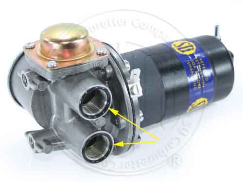 Banjo fittings: Originally there were two flat fibre washers that went either side of the banjo fitting. The fittings themselves can either be flat both sides, or flat one side and recessed the other. Where you have a recess it seems more logical for that side to face the bolt head, as that should have a cylindrical part under the hex part which seems designed to press the washer down into the recess in the banjo. Subsequently pumps were designed with a recess in the face of each outlet on the pump chamber, and in this case a rubber O-ring should be used between the banjo and the pump body. However don't confuse the start of the thread inside the port with this recess, the recess is clearly outside the threaded area, reducing the width of the flat area to less than that of the original fibre washer, as shown in this image from SU Burlen. The kit I received contained two fibre washers and two O-rings, whereas the pump I was rebuilding needs four fibre washers, so you may have to obtain an additional two washers AUC 2141. Examine the faces of the bolt head, banjo and pump body for any nicks, ridges of corrosion and flatten them off. This should be achievable except where the banjos and the pump body have the recesses.
With the inlet in your test liquid, powering the pump should cause it to chatter rapidly for not much more than a couple of seconds while it draws the liquid up towards the pump, then slow to a regular ker-chunk-ker-chunk-ker-chunk as it pumps from the outlet. Blocking the outlet should stop the pump, giving an occasional single click at not less than 30 second intervals. Removing power from the pump, and having the end of the outlet above the level of the liquid but the end of the inlet still in the liquid, and clear tubing on the inlet, the liquid should not drain down the clear tube but be retained in it. Pumping from one container to another, and observing the outflow, there should be a steady and continuous series of pulses with negligible bubbling - bubbles indicates the pump is sucking in air as well as fuel. The pump should move a minimum of 7 gallons per hour, or more conveniently one Imperial pint per minute and in practice double that. That's for older AUF 200/AZX 1200 pumps used on Mk1 cars, the later AUF 300/AZX 1300 pumps used on Mk2 cars onwards should move a minimum of 2 Imperial pints per minute, and again in practice double that.
When you are satisfied that the electrical end in particular is functioning correctly, wrap a couple of layers of insulation tape around the join between the end-cap and solenoid. Important on pumps for chrome-bumper cars to keep water out, less so on rubber bumper cars where the electrical end is in the boot/load space.