
track rods
UJ splines and clamp bolt
Bee's rack replacement
September 2023: However only the 5 thou shim seems to be available at the moment, the smaller 2.5 and 10 thou not, although multiples of 5 thou can be made up of course. Another possibility is that the damper pad can be worn, they are available (ACA5244, stocks vary) but the spring (17H6583) is NLA. I have seen a damper pad rotated by 90 degrees in the yoke to remove the wear and increase the pressure - and worn half-way again! It's also possible to shim the socket in the pad to increase the pressure.
The underside of the yoke (B) showing the damper (D) protruding (left), and the top of the yoke with the damper and spring (C) as would be fitted from underneath: (Anon and John Pinna)
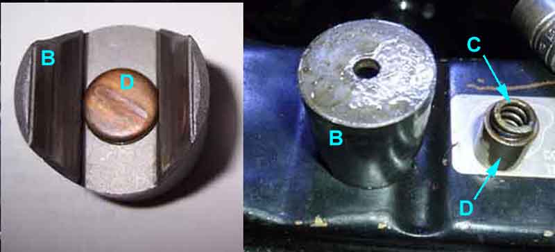
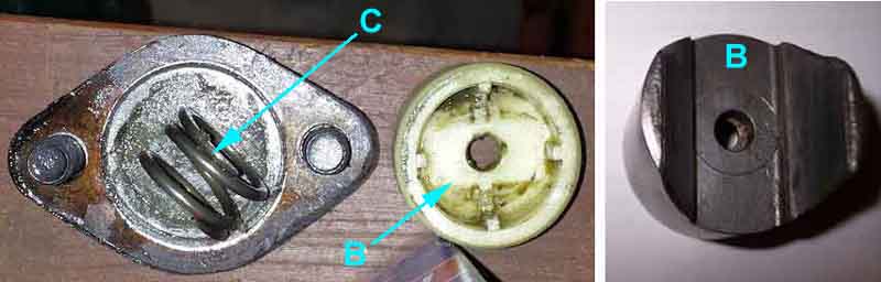
First cost-reduction - nylon yoke (B) with a recess for the spring (C) in the top this time, and no separate damper (left). The underside of this type - in this case metal (right): (Anon)
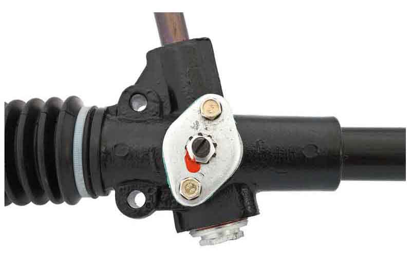
Adjuster screw and locknut, appearing on new racks from sundry suppliers, in this case for the MGC: (Moss Europe)
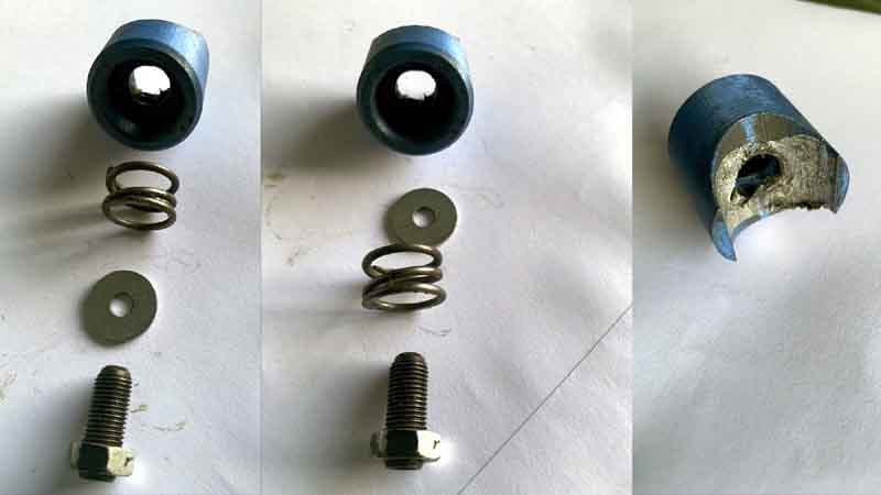
On the left how they should be assembled i.e. with the spring in the yoke and the washer on top of the spring under the screw. In the centre the washer was under the spring and the screw had nothing to press against, resulting in a huge amount of play between rack pinion. On the right the underside of this yoke: (Linton Husbands)
November 2023: Discussing replacement racks with Roger Parker he mentioned that following problems with the first of these racks from South America they are now 're-calibrated' in the UK and are sold with a note to this effect. He went on to say that he hopes that this recalibration is more than just checking the components have been fitted in the correct order! After having advisories of 'inner joint wear' on Bee's original rack I replaced it with a reconditioned hoping to avoid problems such as this, but the reconditioned rack had the same advisories. I replaced that with another reconditioned from the same supplier, and that was exactly the same. I then investigated further and I'm now pretty sure that the problem was caused by pinion clearance, and not inner joints, and because of that in theory the continuous adjustment offered by the screw system would be preferable to the step changes with shimming.
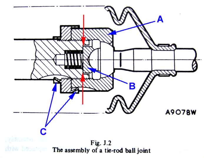
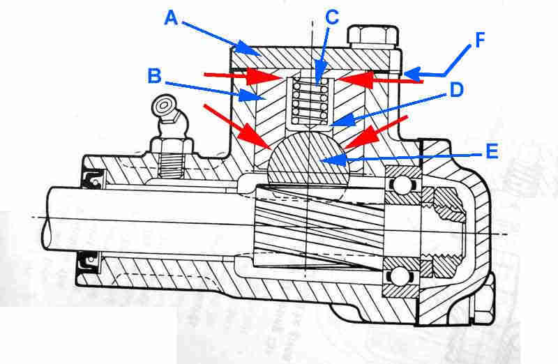
At least, I assumed that was the case as otherwise there would be no need for the spring because the seat is tightened up against the end of rack shaft as shown. But in that case there would be almost no movement of the housing to go from light resistance to articulation to very stiff ... which is what I have found with both used original and rebuilt racks. So I'm wondering now whether the springs (17H2690 NLA) should be very much stiffer meaning it is those that give the correct resistance to articulation leaving a gap at the red arrows, and not the seat hard up against the rack end, otherwise what's the point of the springs? Again in theory a washer could be installed below the spring but if the spring gets coil bound before enough articulation is reached or the seat still reaches the end of the its recess you would be no better off.
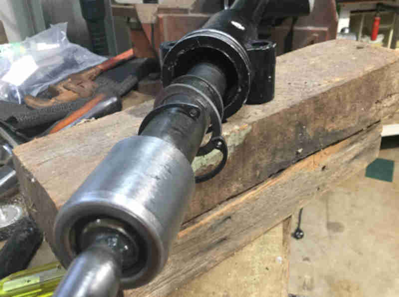
To adjust the articulation force both stakings in the locking ring need to be lifted and the locking ring backed off from the housing. There is a hole in the locking ring for a C-spanner to do this but a pair of Stilsons can be used with care taken not to distort the locking ring, otherwise you will need to unscrew the housing (Stilsons are fine for this) then back-off the locking ring. Without that you cannot turn the housing to increase articulation force (if needed) as the housing is already hard up against the locking ring. In theory if you just lift the locking ring to rack shaft staking then the housing and locking ring can be turned as a unit to adjust the articulation force, but if the two have been locked tightly together like a pair of conventional lock-nuts they will be difficult to move, indeed quite a lot of force is needed to separate them anyway. Once separated the housing is turned as required, then the locking ring turned to lock against the housing without altering the position of the housing. That is tricky, check and tweak before staking the locking ring into the rack shaft and housing.
Joint disassembled, housing removed, locking ring still in place on rack housing:

The spring sits in the deep recess, it can be compressed by the amount it protrudes beyond the wider recess:

The seat sits in the wider, shallower recess:

Another difference with current replacement racks seems to be a 'sealed for life' ball-joint housing: (JP Hall)
However with perseverance JP discovered that the joint can be separated if you use big enough Stilson's! There is still the question of locking the joint against coming unscrewed, as well as adjustment to give the correct level or articulation of the track-rod:
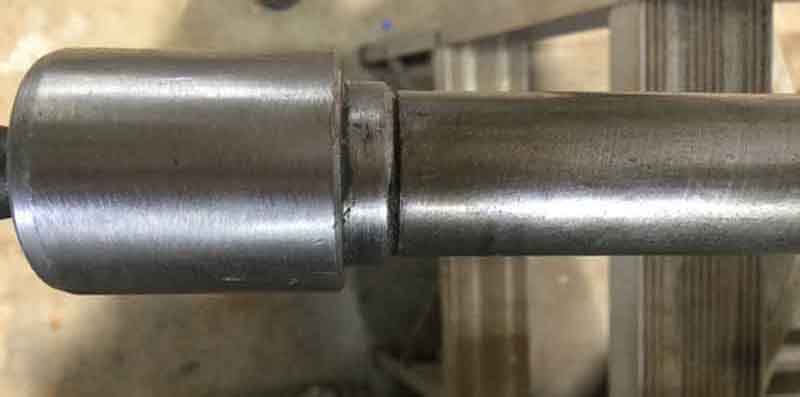
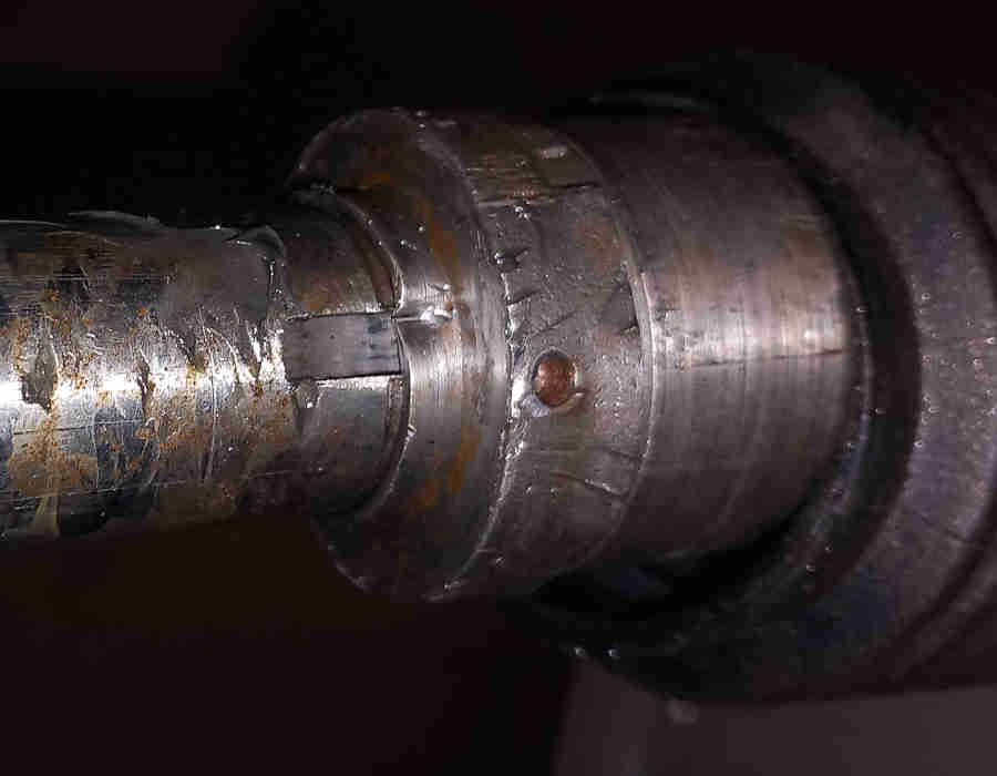
The rack does appear to have a flat which the 'nut' could be flattened on to lock it in position, but it didn't seem to be, which is just well as drastic measures would be needed to remove it.
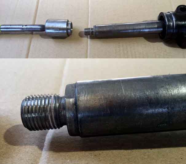
The reason for dismantling the joint was that there was no bush at the passenger side of the rack tube to support the rack shaft, and it flapped about all over the place! Starting inside the rack tube and working outwards there was a washer that wedged against a narrowing taper in the tube, then a gap, then a step in the tube against which a larger washer sat, then a groove against that with a circlip. So it looks like there should have been a bush of some kind between the two washers to support the rack shaft, but there wasn't. This was a replacement rack with the adjuster screw and locknut for the damper, as above: (JPHall)
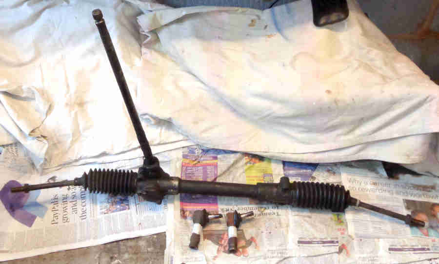
Bee's rack replacement: January 2023
Can't move the TRE pins by hand so they can go back on.
Collected the replacement and dropped off the old two days later, the irony is that it comes complete with TRE lock-nuts, so now I have a couple of spares:
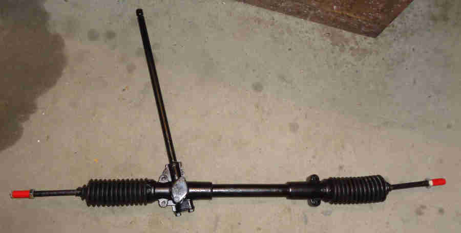
TREs screwed on - added together the 21.5 and 20 turns needed to take them off and divided by two which should give an even number of turns to lock as well as hopefully close to the correct tracking. It'll be interesting to see how the steering wheel lines up when the car is travelling forwards, I might need to add a bit to one and remove a bit from the other if the wheel ends up between two splines although laser-based tracking adjustment should do that as a matter of course:
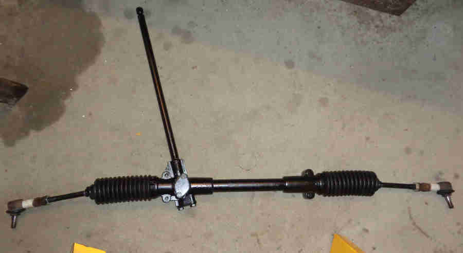
Nylon yoke instead of steel and copper-coloured damper so probably won't last as long, but clearance set by shims which is better than the adjuster that others have had problems with. Grease-lubricated so no more leaks. Bee's rack shaft was very easy to turn by hand and wheels up could be spun from lock to lock with a little finger-tip, probably a factor of the play in the passenger-side bush. This is stiffer even with the pinion cover slack so that is coming from the bush, I hope it's not stiff enough to prevent self-centring on the road. Speaking of 'lasting' I wonder how long the gaiters will last:
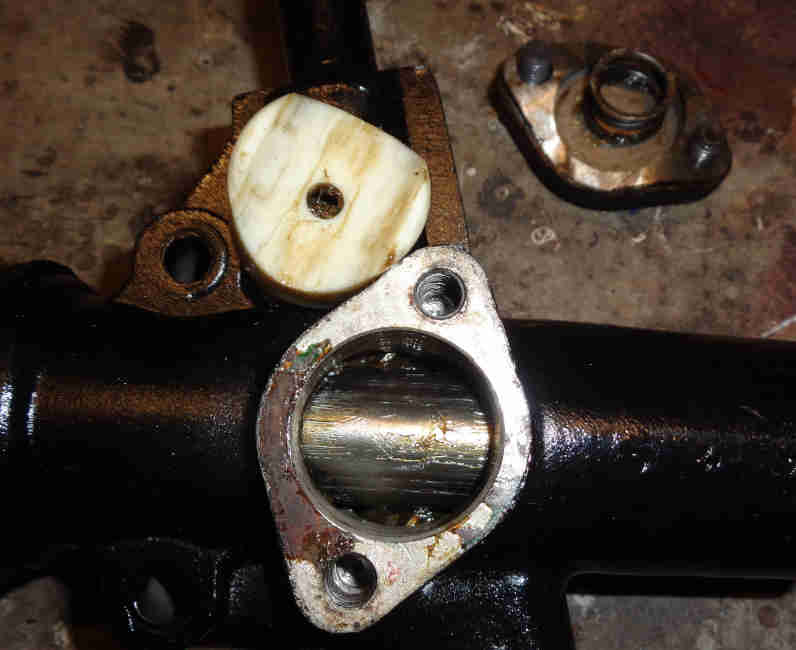
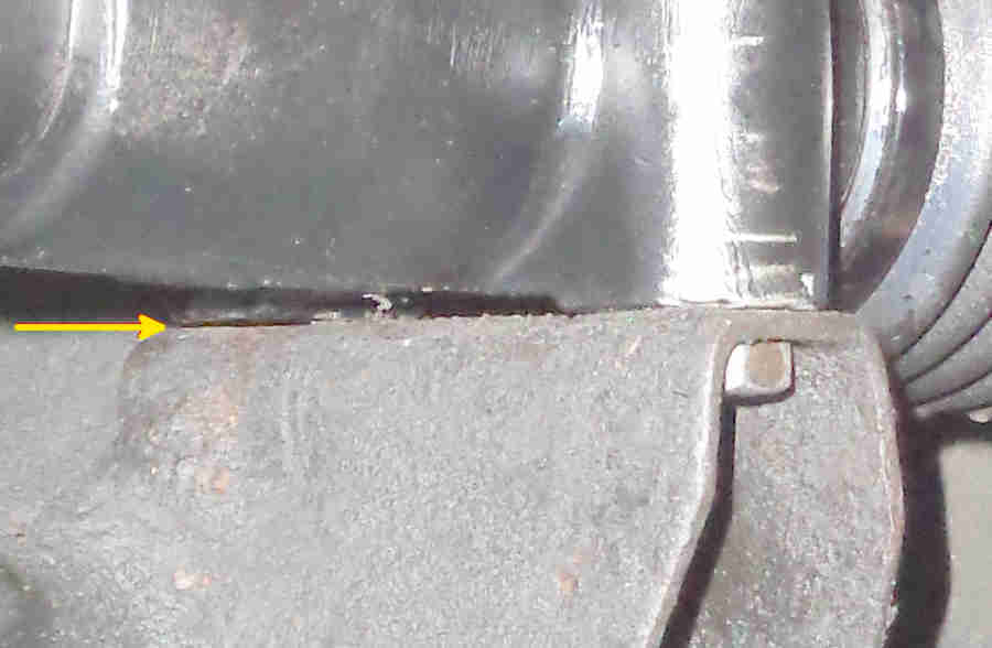
With three bolts nipped up there was a 12 thou gap between the rack and the cross-member bracket at the passenger side rear that needed to be shimmed:
Never mind the gaiters, seven months and 1500 miles later this new rack gets an advisory 'both inner joints worn' i.e. exactly the same as before!
Note that the front bolts are fitted up through the brackets and rack with the lock-washers and nuts on top, not the other way round as for the rear bolts which go into welded nuts inside the bracket. There is a section of weld inside the bracket that holds the bolt head still while tightening the nut from above:

Both my cross-members are the same, but a person very experienced in MGBs (who shall remain nameless) spotted them and said they were upside down, my MOT place has said the same, and Vitesse Global when fitting my 5-speed gearbox put them in the other way (now corrected ...). Not too bad upside down if the washer is no wider than across the flats of the bolt or nut as it will allow the nut to sit square. But if the washer is wider one side will sit on the weld and the other side will angle towards the bracket, greatly reducing the clamping area. If they could weld a nut in the deeper recesses for the rear bolt it begs the question as to why the same wasn't done at the front - damage from road rocks to the exposed thread whereas the rear bolt is protected by the sides of the bracket? But there we are.
Bee's 2nd replacement: October 2023
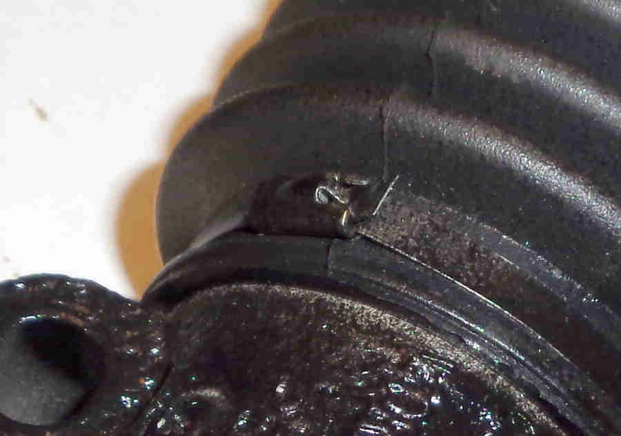
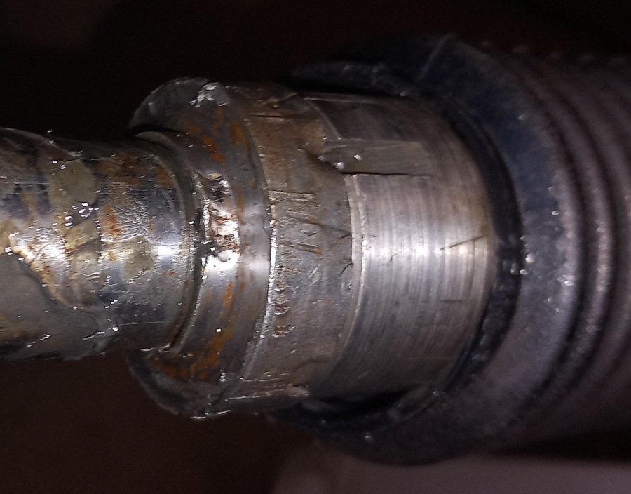
Nevertheless as both inner joints have only about 1/3rd the articulation force I dive in to find them as per the WSM so can be adjusted. The original staking of the locking-ring to the rack ...
... and to the bearing cup. Well chewed so re-used which is not surprising as they are NLA:
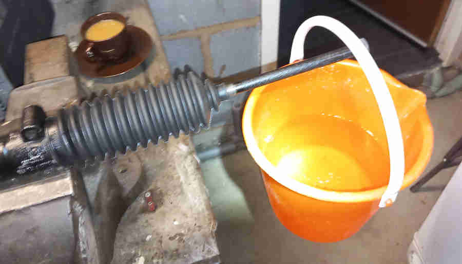
Staking released and bearing tightened to closer to the specified force using grips and Stilson's ... using a bucket of water weighing 6lb positioned 7" from the joint, which equates to 42 pound inches i.e. mid-way between the WSM 32 to 52 pound inches:
However that proved to be too tight and variable in practice so I backed them off until there was the same resistance through full articulation.
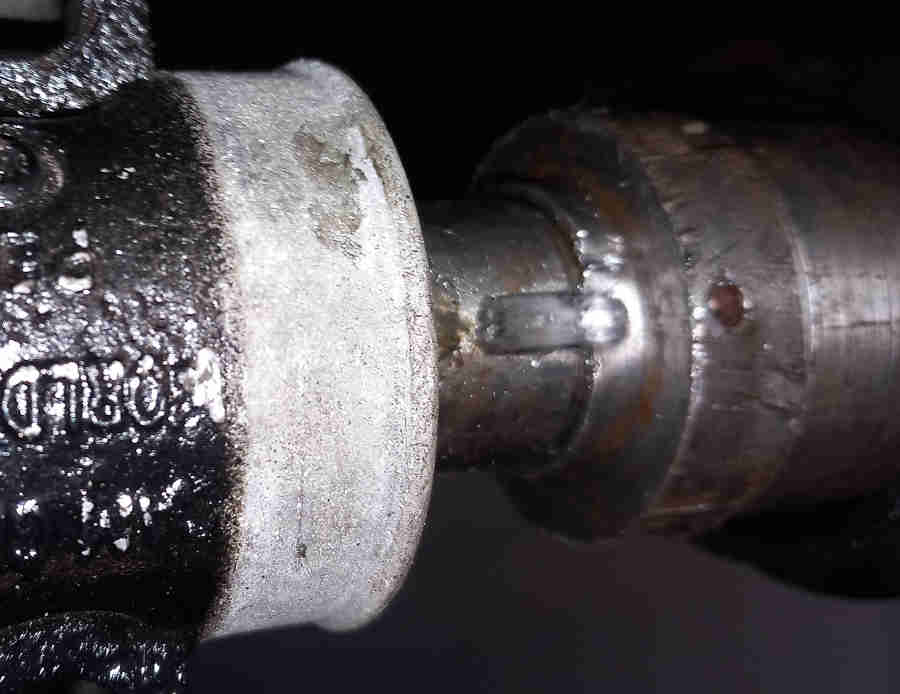
Bearing cap with locking ring tightened just a few degrees and restaked:
The other side was the same, only took about 90 mins from start to finish, just gaiter ties to replace, leaving the small one slack pending tracking adjustment.