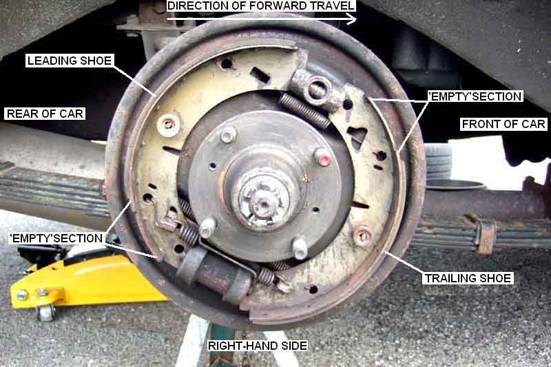
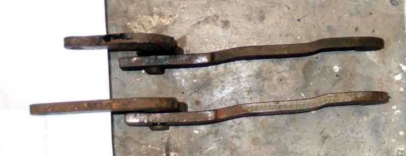
Right-hand side ditto:
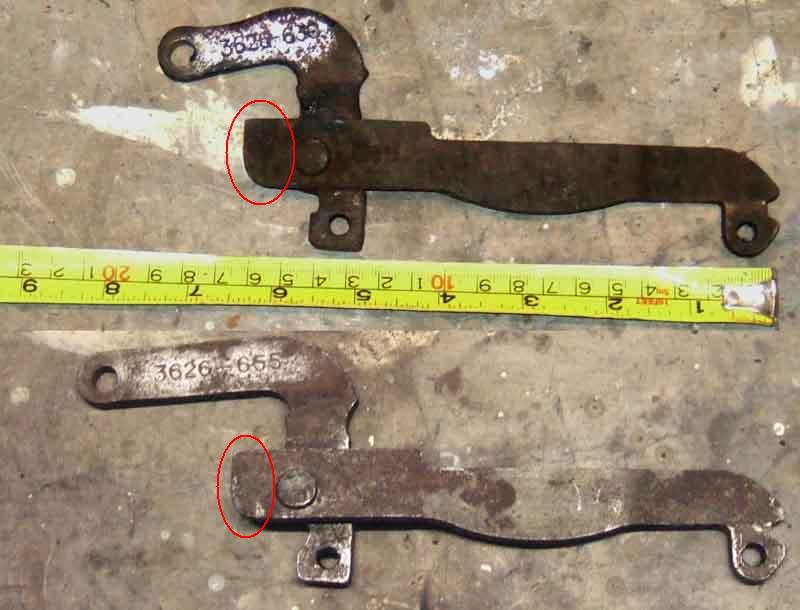
Early lever (top) with the short lever with a curved profile, and about 1" shorter than the later lever. Other than that the long lever has exactly the same profile on both types (note extension circled) ...
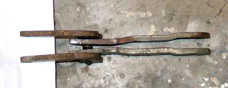
A pair of the same type have mirror-image bending of the long levers ...
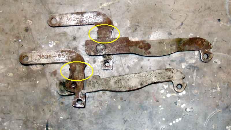
... but identical short levers, they are just fitted to the other side of the long lever. That is why the numbers stamped into the short levers are the same for both sides, and when installed one faces up and the other down. (Circled is the waisted section where the slot in the rubber boot is pushed down to when fitted).
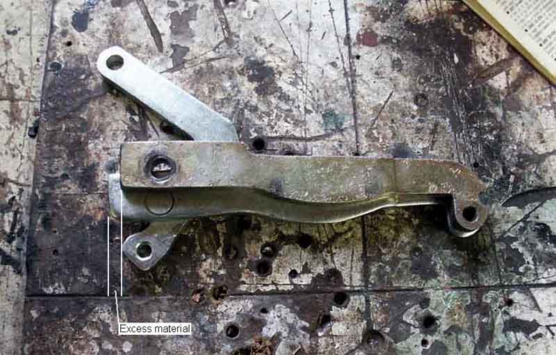
Toni Kavcic's original (short lever detached) on top, new one below, both being for the right-hand side. The excess material on the long lever of the new item was fouling the back of the rear shoe and holding it further out such that the drum could not be refitted, even when the levers were installed the correct way up i.e. long lever above short lever.
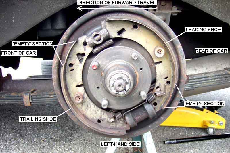
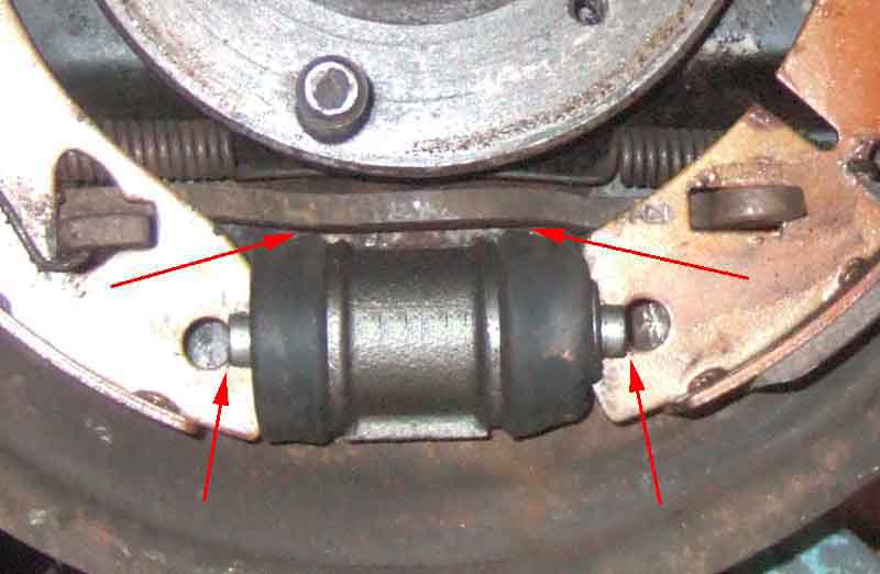
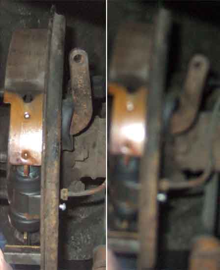
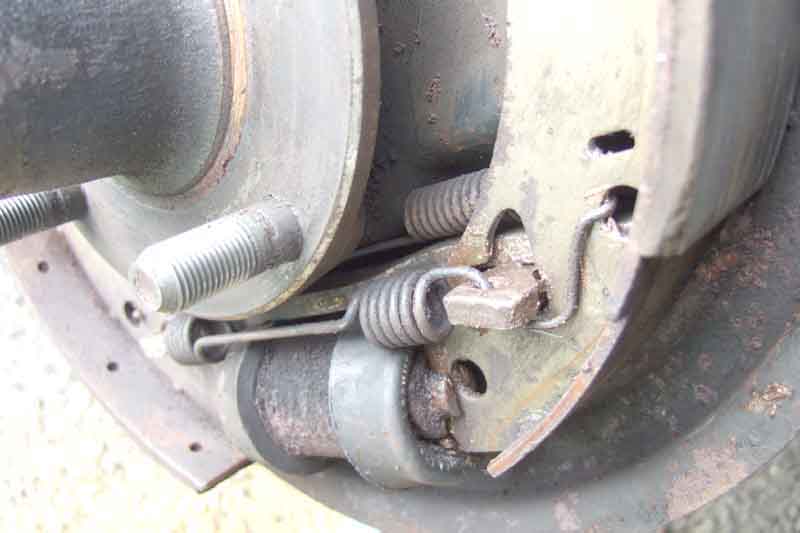
Salisbury/tube axle: Installed correctly the long lever has one kink so it is lifted away from the slave dust-cover (right arrow), and another to further lift it over the short lever (left arrow). This allows the shoes to sit such that the holes are pretty-much in line with the slave pistons. Notice also how the holes sit just inside the slots in the pistons.
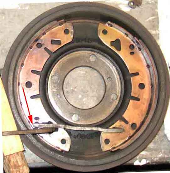
Looking from the backplate side (placed in a drum), installed correctly the projection at the pivot end of the long lever just clears the back of the shoe (arrow) and the ends of the shoes are about the same distance apart.
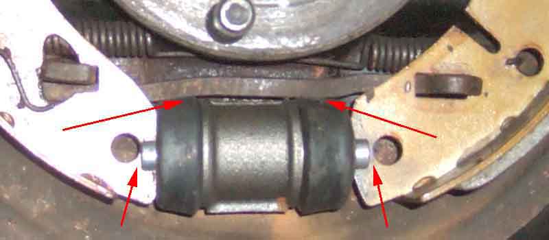
Installed incorrectly (before fitting the third spring) the long lever turns down to lie on the slave dust cover (right arrow) then turns further down (left arrow). This lifts the shoes up - holes in shoes are now above slave pistons - and forces them out - the holes are now pushed away from the slots in the pistons, and both of these aspects can prevent the drum fitting over the shoes. The rear shoe doesn't want to sit flat against the back-plate, and the long lever binds on the slave dust-covers making handbrake operation stiff and weak.
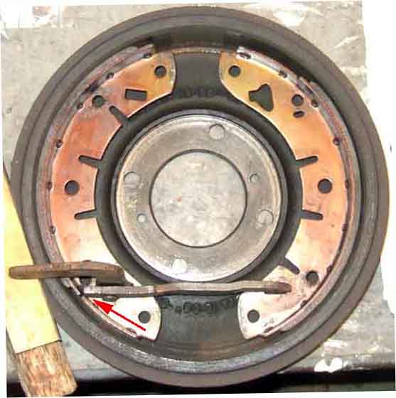
Installed incorrectly the projection at the pivot end of the long lever fouls the back of the shoe (arrow), pushing the tops of the shoes closer together and the bottoms further apart, and pushing the rear shoe away from the short lever.
Installed incorrectly because the pivot end of the long lever is pushing the rear shoe away from the short lever, there is a huge amount of free play in the short lever (unfortunately I didn't notice the poor focus until after everything was back together on the correct sides). All of these issues are exactly the same with both the early and the later levers, when the levers are incorrectly installed with the short lever above the long lever. All of these aspects are exactly the same no matter which lever type is fitted to the axle, which is a Salisbury in this case:
It's complicated by that page being about a repair done to an MGA, with a rear brake arrangement identical to the Salisbury tube axle on the MGB, whereas other sources show the rear brake arrangement on an MGA as being completely different to the MGB having a sliding wheel cylinder with only one piston, the handbrake acting on the cylinder and not the shoes. Then again yet more sources talk about converting the MGA rear brakes to MGB for reasons of cost, and MGB banjo parts do show the levers acting on the shoes, so at the end of the day the levers must be the same on both banjo and Salisbury/tube.
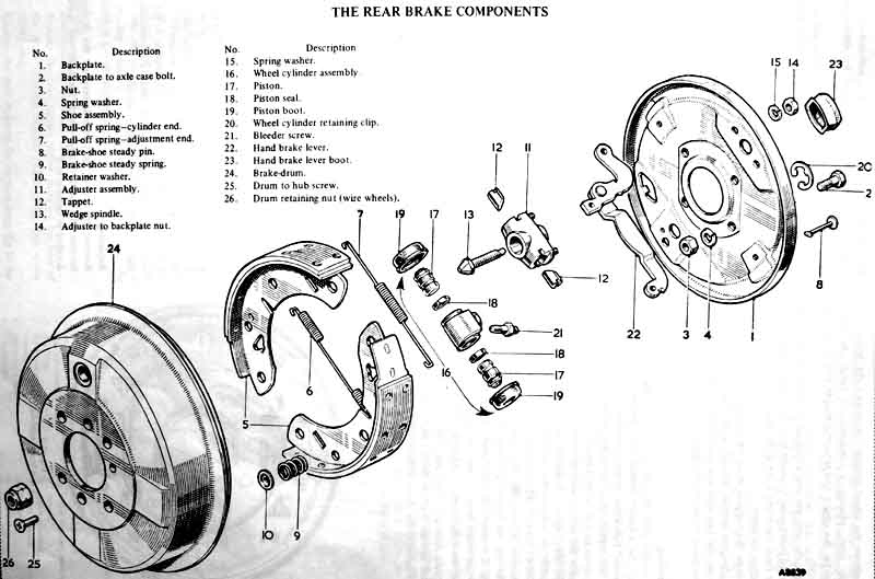
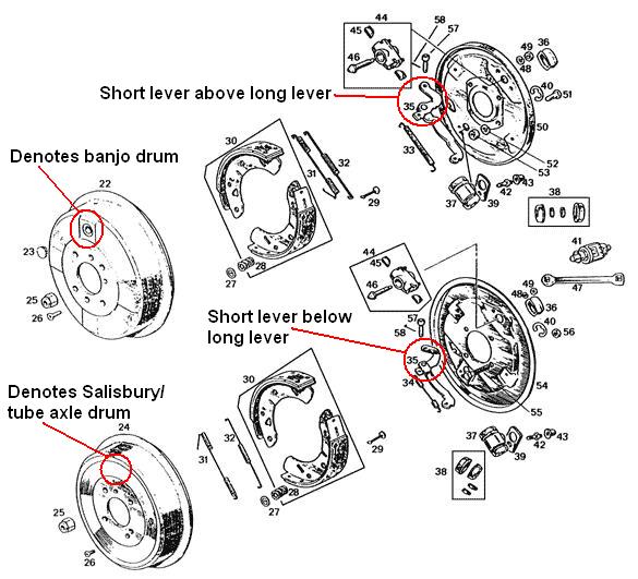
This from the Leyland Workshop Manual clearly shows the long lever below the short lever, with the banjo brake drum with the large hole in the face. One end of the lower inner spring (6) can't be seen, but the Parts Catalogue indicates it is the same part for both banjo and Salisbury, and so the end with the long wire hook must be in the front shoe. There is a drawing in the Haynes manual that also shows the short lever above the long lever i.e. in the banjo position, but it doesn't show the face of the brake drum so at first sight it isn't possible to work out which axle it represents. Haynes also shows the lower spring with the long end in the front shoe. Neither Haynes nor the Workshop Manual have drawings of the Salisbury arrangement.:
Drawings from the Leyland Parts Catalogue showing the banjo and Salisbury/tube axles. This shows the long lever below the short lever for the banjo axle as per the Leyland Workshop Manual, and above the short lever for the Salisbury/tube axle. On the banjo axle the lower inner spring (5) is orientated with the long end in the front shoe, and shows the handbrake spring (19) with a single long coil. For the Salisbury axle the lower inner spring (4) has the long wire in the rear shoe, and the handbrake spring (17) has two fatter coils. The banjo drawing depicts all the components as if looking onto the right-hand end of the axle, but confusingly for the Salisbury axle the backplate and most of its components are as if you were looking outwards from the middle of the car towards the left hand end of the axle, but the adjuster, shoes and drum are depicted as looking from the right-hand side. Even if this confusion has resulted in the Salisbury levers being shown the other way up, which other parts suppliers have simply followed, it still doesn't explain why the banjo long lever is shown on the wrong side of the short lever:
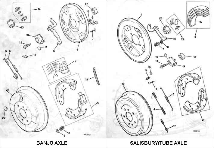
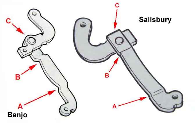
Detail from the above. Note how the long lever for the banjo axle is kinked up from the front shoe to clear the slave cylinder (A), then back down again to pass under the short lever (B). Neither of the two lever types that I have seen are like this, and there is no extension of the long lever past the pivot at C. Not quite as easy to see but for the Salisbury axle the implication is that the long lever kinks up from the front shoe as before (A), then kinks further up to pass over the short lever (B). There is also the extension to the long lever past the pivot at C. Both lever types in my possession are like this:
Drawings from Moss Europe web site showing the banjo and Salisbury/tube axles. The orientation of most of the components is correct, and helpfully shown from the same (right-hand) side of the car looking onto the shoes, but it still shows the banjo long lever passing under the short lever, and the Salisbury long lever passing over the short lever (circled). This also shows the lower inner spring (31) with its long wire in the front shoe and the handbrake spring (33) with the single long coil for the banjo axle. For the Salisbury axle the long end of the lower shoe spring (31) is in the rear shoe, and the handbrake spring (34) has two short and fatter coils. Moss US only shows the banjo arrangement:
Other suppliers show the levers without any indication as to which side it might be for, some the 'mystery' type and some the later type. However all depict them with (incorrectly) the long lever under the short lever with the exception of David Manners Group, but even that is incorrect as the one shown as being for the left-hand side was actually the one for the right and vice-versa. Motaclan/Leacy goes one further by mixing up the left and the right as well as showing the long lever on the wrong side of the short lever. So if you only purchase one, shop carefully! If buying mail order it will be less hassle to get both even if you only need one ... unless they send you two for the same side.
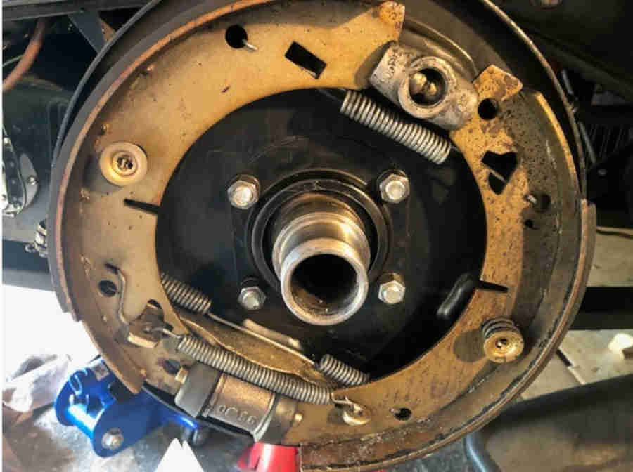
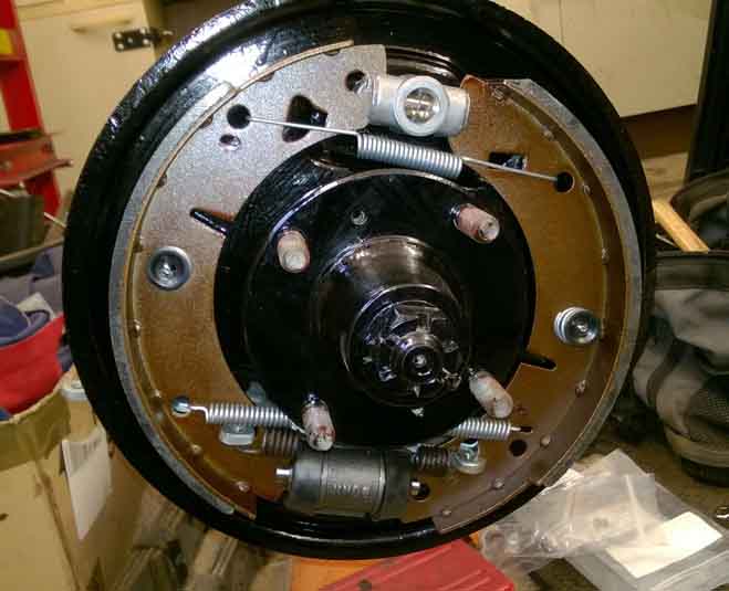
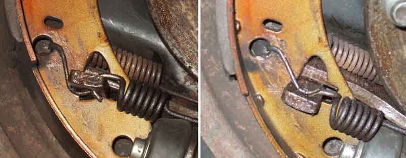
It's always been a fiddle fitting the top spring behind the shoes, I wondered if it could go on the outside, and out of many images showing it behind I came across this one with it like that. I've asked the site owner how that came about and he said that is probably how he found them to begin with. As part of stripping one wheel to replace the handbrake lever boots I refitted that spring on the outside and it was way easier. Drives fine, MOT next month so I'll be able to see if there is any difference between sides. This also shows the lower shoe inner spring on the outside as well (and using one hole and one slot instead of two holes). I don't think I'd do that as that's the one I put in the shoes before offering them up to the brake lever and wheel cylinder as a pair, and that is relatively easy:
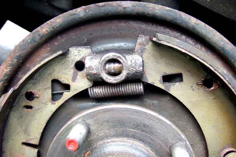
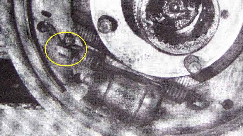
Detail of bottom springs showing the inner spring also mounted in the holes and not the slots. The outer handbrake spring goes through holes in the ends of the handbrake lever, with the wire between the coils positioned away from the long lever. Haynes incorrectly shows this in the inner position, where it rubs on the long lever. This is the later spring, the earlier version has a single long coil. The change point seems to have been with the levers, not with the axles as implied by the drawings. Maybe the orientation of the inner spring i.e. whether the long wire end came through the front shoe or the rear, also changed with the levers and not the axle:
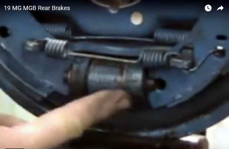
I'd never understood why the inner spring has the long extension coming through the rear shoe as in the above picture (Salisbury axle, drawings show it in the front shoe for banjo axles, which may be an error - there are many of them). Haynes shows this correctly using the hole in the shoe and not the slot, but resting on top of the handbrake lever. I've always felt that was wrong as it was easier to fit underneath - until I saw a drawing for Sprites/Midgets that described it as an anti-rattle measure for the handbrake lever, also curled round the lever as I fit it, and John Twist specifically states it goes like this at 5:05:
If it is an anti-rattle measure then it probably should be above as Haynes shows it for two reasons: One is that underneath the lever is only resting on the spring and there is plenty of free-play in the slot in the shoe above the lever for it to move around. The other is that when underneath the lever is resting on the cut end of the spring, which for moving parts seems poor mechanical practice, and having it above with the smooth loop of the spring pressing against the lever would be preferable, as well as being more effective as an anti-rattle measure. It can be positioned either below or above, although to position it above takes more effort. However with it below there is no tendency of the levers to rattle in the shoes given the third spring on the levers, so there is no point in struggling to get it on top, and no drawbacks to having it below:
Haynes showing it above the lever:
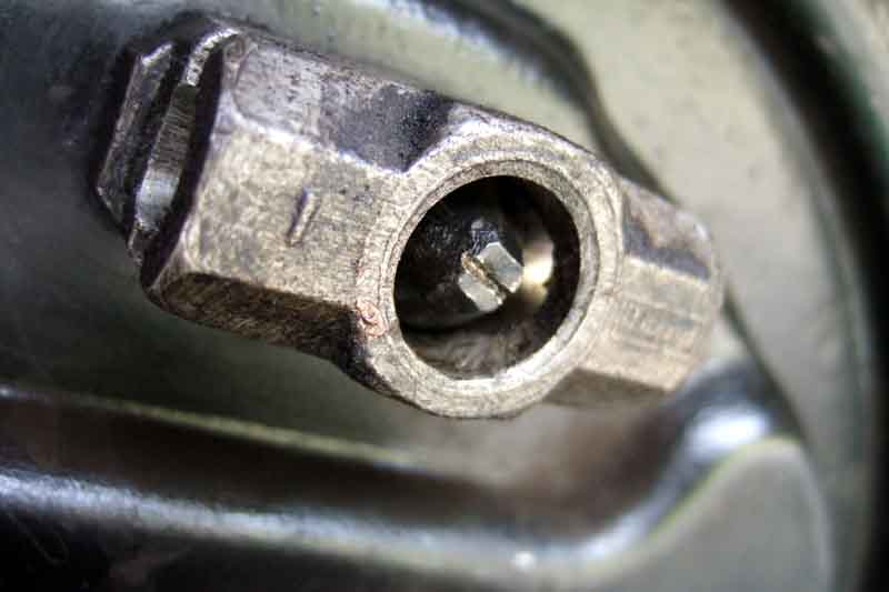
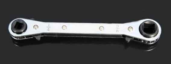
When looking at a couple of John Twist videos while investigating the 'anti-rattle' feature mentioned above I noticed he was using a ratchet spanner with a 1/4" square hole which directly fits the adjuster, and he happened to mention it was a refrigeration spanner. Various Googles later I come up with this, with four square-drive sockets including 1/4" - select CT122, which is a bargain at Ł4. OK I may not use the other three very often if at all, but seeing as how a single 1/4" from Sealey is Ł14, it's no contest. Makes winding the adjuster out from all the way in with the shoes refitted a doddle, although to be fair having the plain adjuster spanner as well for the final adjustments back and fore is slightly easier than flipping the ratchet to change direction each time: