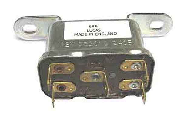
A general view of a typical 6RA 4 terminal, 4 spade type:
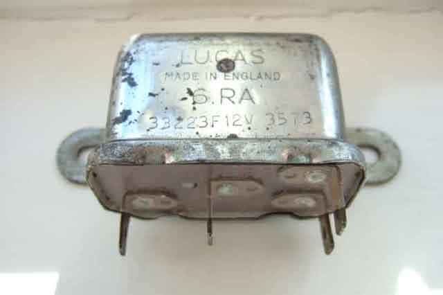
Four terminals but five spades. The double spade on terminal C1 offers a convenient branching point for a 12v supply wire to another circuit:
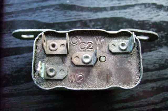
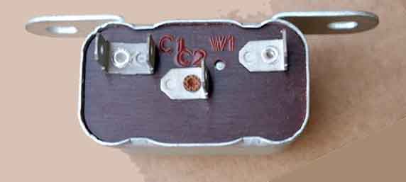
An alternative 4 terminal, 4 spade but with W2 in a different position and a C3 instead of a C1. This is a relay where the contact is 'normally closed':
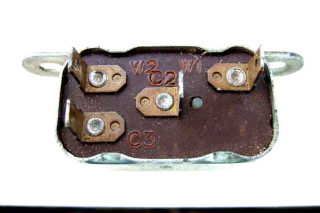
Five terminals and five spades, this has a 'changeover' contact i.e. when the relay opens it switches a common contact (C2) from a 'normally closed' contact (C3) to a 'normally open' contact (C1):
The three terminal, four spade relay 33188/SRB102 originally used for the cooling fans in V8s. The system may have been dealer-modified with a 4-terminal, 5-spade relay to take the load of the fans off the green circuit fuse. Seemingly obsolete, they were also used on Standard/Triumph, BSA motorcycles, Cobra, Jaguar/Daimler and Ferrari, for the horns and other circuits. Contrary to several opinions the missing fourth terminal (W2) is not replaced with an internal earth i.e. via the can, but instead is internally connected to the C2 terminal. The 12v supply is connected to this terminal, an earth from the switch is connected to W1 to operate the relay to the C2 12v supply, which is then extended out through the C1 terminal to operate the fans or horn: (TR Register)
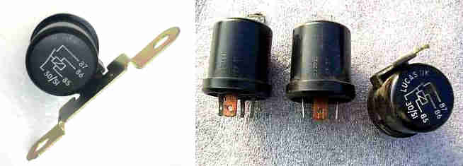
Cylindrical Lucas relays used on later MGBs, designated 26RA, SRB402. These can have either the same mounting points as the 6RA (left), or a single mounting point creating space for an additional relay if needed:
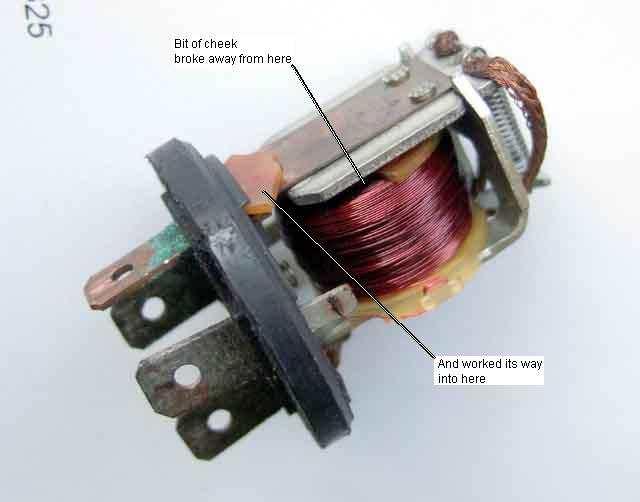
Took this off a friends car as although it was clicking as the ignition was turned off it's output was permanently energised, which had flattened the battery. Opened up (never could resist) to find one of the coil cheeks partly broken away, which had worked itself round to the back of the armature, holding the contacts closed all the time. For a start it must have been sculling around in there for ages before getting into that position, and I'm amazed the gap was big enough for it to slide in, yet small enough to keep the contacts closed! You couldn't engineer it to do that!
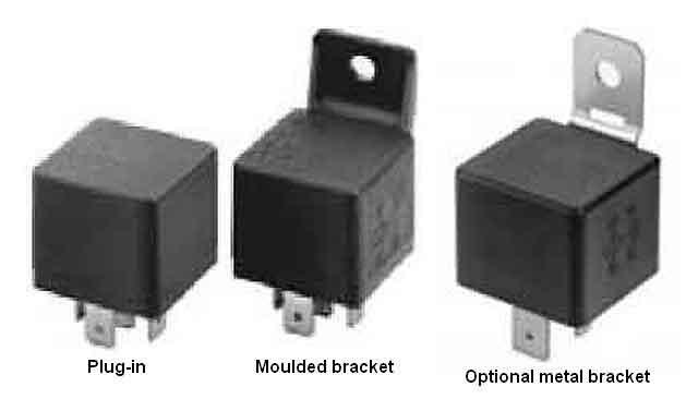
Cube-type Lucas 28RA SRB520 relays also can be found on late MGBs, identical to current (pun not intended) after-market relays
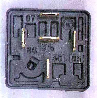
Terminal arrangement, pin 30 is usually adjacent to the mounting bracket
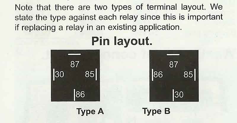
However! Note that these relays can have two different terminal layouts, 30 and 86 swapping places, as below:
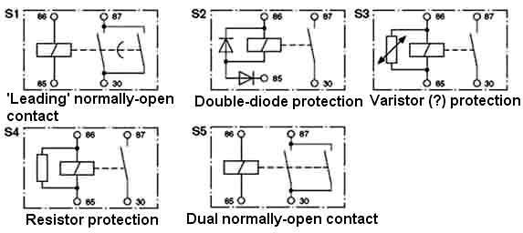
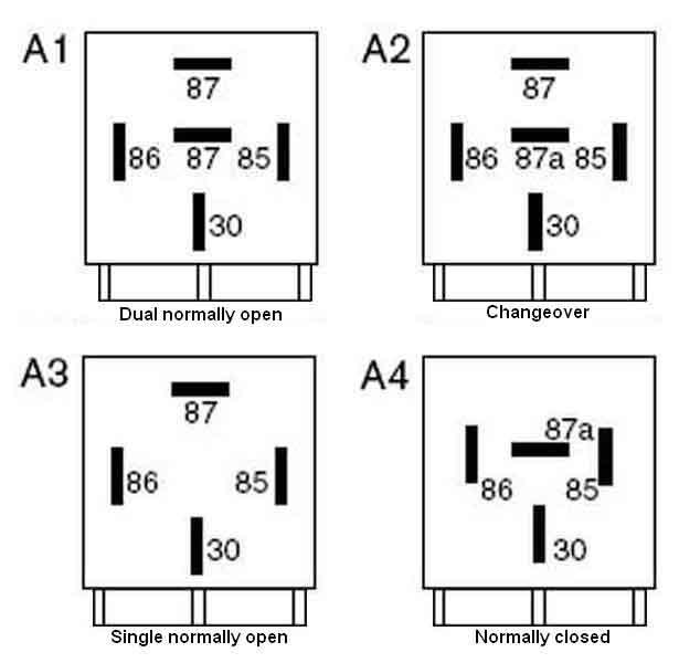
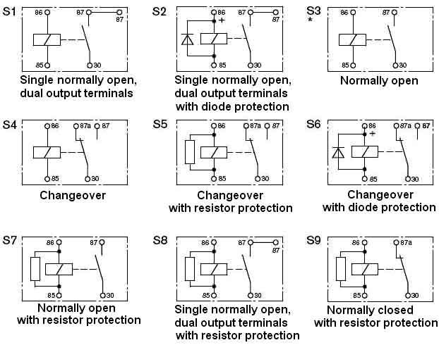
Internal circuitry of standard relays. Note that with S2 and S6 single diode protection the power supply to the winding must be connected the right way round or it will blow the diode, +ve must be connected to 86 and -ve to 85. Resistor protection isn't polarity sensitive, but doesn't give as much protection to the operating circuitry as diode protection:
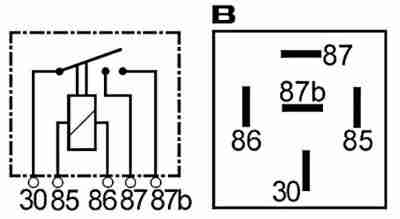 One not shown above is this dual make (aka double make, twin make) relay which connects the input to two separate output contacts (87 and 87b), when the relay is released the two outputs are isolated from one another. This relay can be used to reinstate the coil boost function when replacing the starter motor on RB cars with an after-market alternative. Not to be confused with high power relays with one or two 87 terminals but no 87b terminal.
Internal circuitry of power relays. S1 has a tungsten contact that closes first and opens last, and a lower resistance contact which closes last and opens first. The tungsten contact protects the lower resistance contact against the back emf and high current from large inductive loads. S2 has double diode protection, the series diode protecting the parallel diode from damage through reverse connection, if reverse connected the relay simply won't operate. As before +ve is connected to 86 and -ve to 85: