
There doesn't seem to be anything preventing use of the reversing lights as supplementary brake lights in the MOT Manual Section 4.3 other than the comment: "Additional stop lamps, over and above the mandatory requirements, must be tested. However, if you are not sure if they are connected, you should give the benefit of the doubt." The Road Vehicles Lighting Regulations 1989 is a little more complicated indicating that vehicles first used from 1st February 1974 may need optional stop lights (Part II) to have an approval mark (paragraph 5 (a) and (b)), and there is also both a minimum and a maximum wattage quoted from 1st January 1971, but 'no requirement' on intensity.
The same supplier has other 'bare board' LED modules for things like courtesy lights which gave me the idea of looking at the reversing lights to see if such a thing could be fitted behind the standard lens, as the high-cost items seem to be. A board of 24mm x 36mm would fit neatly into the recess for the standard festoon bulb, and could accommodate 24 5mm LEDs i.e. 12 white and 12 red. I did some browsing for the brightest I could find and came up with these 48CD white and 65CD red in the clear casings. The 'CD' number gives the intensity, usually LEDs are shown with four digits and 'mcd' i.e. thousandths of a CD and so are less than 10CD, so these are pretty powerful. As the brightness goes up the viewing angle tends to go down, i.e. 15 degrees in the case of the white and only 8 degrees for the red, but behind the bobbled lens of the light unit there will be more spread, and particularly for brake lights straight back to following vehicles is the most important. Both having clear casings is also handy so there is no red showing behind the lens when both are off. I couldn't get anywhere near the output from eBay sources i.e. free postage, they only cost pennies so come to less than the Ł30 minimum spend, 'free' delivery, but a non-trade 'handling charge' of Ł10, so definitely worth ordering parts for both lights in one go even if you don't end up making both of them. RS Components are half the handling/P&P but one of the LEDs won't be available for another six months, so there we are.
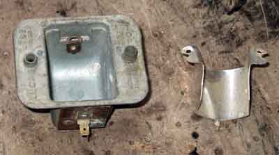 With three wires I would need to drill a hole in the side for the brake light wire, didn't want to do that to Bee's 'originals', so looked at Andy Jennings and he had them for Ł3 each. Same postage for two as one so I had two in case I decided to install them to both sides, plus Ł4 P&P so another tenner, and don't need the lenses of course. I drilled a small pilot hole in the side of the housing about half way up and near the back, and it took quite a bit of effort even with a specialist drill that goes through steel like a knife through hot butter, but this is 'Mazak' i.e. a magnesium alloy. With that hole drilled two further drills to widen it out to about 10mm had no problem. The final size was governed by blind grommets I already had, for the brake wire to come out. The reflector would be in the way but pinged off in a couple of seconds.
I did some experiments with various resistors in series with the LEDs and 12v measuring voltage and current to decide how to interconnect each group of 12. The white ones have a forward voltage of 3.2v 20mA and the red 2.2v at 50mA, so three in series would be 9.6v and 6.6v respectively, and four of the whites would come to 12.8v. They have to total less than 12v as otherwise any resistor would end up being a very small value, even higher would reduce the available voltage to each LED, so I decide to wire them in groups of three in series i.e. four white groups and four red, which would need eight resistors. I could have experimented further with wiring three triples in parallel with a single resistor for the whites and another for the reds, or even wiring all eight triples in parallel and putting a single resistor in the common earth connection, but didn't. I ended up with 270 ohms 1/4W as the series resistance for both white and red, using a lower value for the whites made no apparent increase to the brightness and I had ten of the resistors to hand.
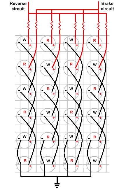 I cut out a section of PCB to fit in the reverse light recess. I only have copper-strip PCB so have to carefully cut the tracks so the LEDs don't interfere with each other even though I don't intend to solder them to the board. I'll interconnect them about 1/4" off the back of the PCB using the wires as the LEDS are pushed through until flush with the front. Soldering to the board with such a short length of lead could damage them. If I soldered with the LEDs proud the PCB would need to be smaller to fit further back into the tapered recess of the housing. The LEDs are fitted into the PCB as a matrix i.e. white red white red across the top row, then red white red white across the next row down, and so-on. For each group of three I bent the -ve terminal of the top LED down to the +ve of the next one, sleeved both and soldered them about 1/4" away from the PCB. That leaves me with a white +ve and a red +ve at the top of each vertical row on the PCB, and earth or -ve connections at the bottom. Resistors were soldered to the +ve of the top white and top red in each vertical row and sleeved, then the four whites were brought together and a single wire soldered, ditto with the four reds. At the other end the bottom but one -ve was soldered to the bottom -ve, then those four were sleeved, brought together, soldered to a single black earth wire and that connection was also sleeved.
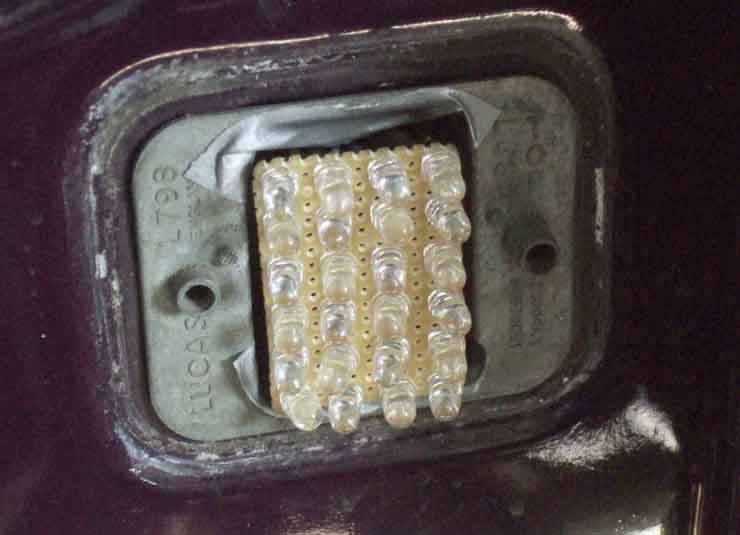 I had intended to solder the white +ve and the black earth to the connectors for the festoon bulb and only bring the brake wire out, but space was getting a bit tight the way I'd wired it so brought all three out through the side of the housing. For the other side I'll try doing things a bit differently so the reverse and earth wires can remain inside. I tried soldering the wires to the 'silver' rivets that were attaching the spade connectors to the housing but no go. The spades are L-shaped and I was able to clean up the flat part and solder to that, which didn't interfere with the harness plug going on the spades. Because I had used copper-strip PCB the ends of some of the tracks were 'live' didn't want those coming into contact with the housing, so put some duct tape in as an insulator. The piece at the bottom is probably superfluous as that end is all earths anyway. I could have cut the tracks back from the ends but at this stage didn't want to damage any of the connections. Something else to remember for the other side. The off-side brake light bullet connector is a 4-way with only three wires (green/purple) so there is a spare hole for the additional wire that side. The near-side uses a 2-way connector as there are only two wires, so a 4-way is substituted.
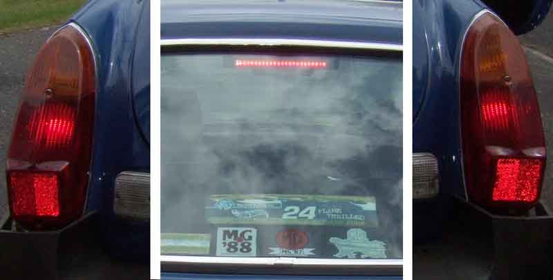
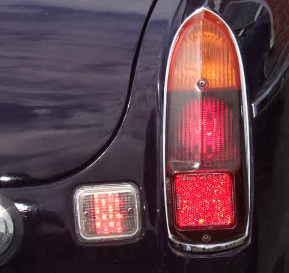 In use in direct sunshine. Tricky to get an accurate representation in a photo as the an area is averaged to set the exposure, even when 'spot' mode is used. Hence the yellow or white spots of light dotted through the red part of the lens which is where the intensity has exceeded the range of the sensor. But still an improvement in visibility I suggest as it is an additional light coming on, changing from white to red, and better in practice than here.
 Reverse lights clearly much brighter, not just whiter, with very good spread to the sides and down despite the narrow angle of the actual LEDs. You could achieve this effect, without the brake-light function, with an LED festoon although get the Cree type with additional electronics visible such as these as 'standard' types with only the elements visible whilst whiter than incandescent are no brighter. When doing the left-hand side I realised that bulb was well blackened, unlike the right-hand side when I took that out, so part of the reduction in light that side is down to that.
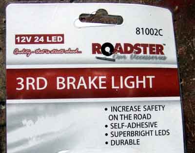
So one duly ordered ... but when it came I realised I had ordered the wrong one ...
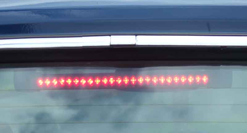
Interestingly mine has LEDs all the way across, no gap like John's (which turns out to be from a radio aerial stuck to the glass blocking two of them). The ultimate in flimsy wires, and nowhere near long enough. I shortened them to about 3", soldered on some standard wires, and with a couple of thicknesses of heat-shrink each became about as fat as a 2-way bullet connector, but shorter. These I superglued into the recess in the ends that the LED strip pivots on and tucked the flimsy wires in afterwards, so there is no strain on those. The earth I ran under the rear cant rail cover as far as the load-space light and used a through-hole terminal under one of the screws. Having replaced the C-post cover in the past (and what a pain they were) I wasn't going to remove them again, so pulled out the foam packing and fed the 12v wire part under the cover and part with the other wires inside the C-post, down to the 4-way brake light bullet connector which on the off side only has three wires and hence a spare hole.
Again very difficult to photograph on what was a bright day in near sunshine to get a true representation of what it would be like on the road.
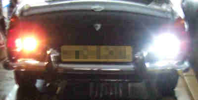
I wanted a single image of all three lights for comparison, but with standard exposure the LEDs came out as little white dots almost invisible against the glass reflecting the sky, again because the intensity was exceeding the capacity of the camera sensor. So stopped right down to get this ... and yes the standard brake lights are on! Also the apparent intensity to the eye is much more than appears here, more than I was expecting for something so cheap, so worthwhile.
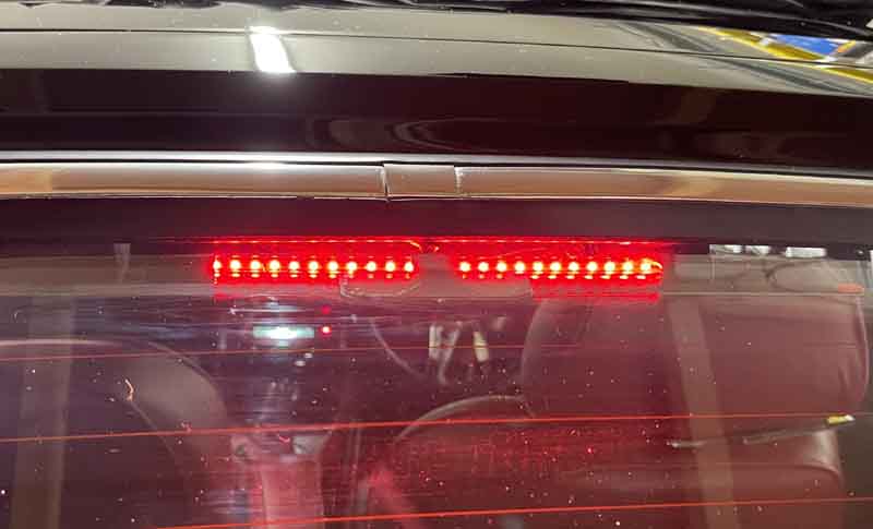
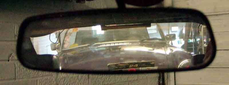
I had wondered beforehand about impact on the rear view mirror. John said it was fine, and although it is visible at the top short of an Close Encounters of the Third Kind I doubt it will be a problem, I haven't been aware of it when using the car since:
Subsequently I think about supplementary fusing - I don't want a problem with any of my changes blowing the main green-circuit fuse. I want a different fuse-holder so I don't fit a 17 amp in error, in-line for convenience, and I find these 20mm screw-type holders (they took over a week to arrive so link deleted, there are other eBay sources) which should be just the job. Paraphrasing the 1987 sci-fi film 'fuses not included', but I have some 4A so they will be fine. I'll fit one where the green/brown in the main harness joins the rear harness in the engine compartment for the roadster reversing lights, and one where the connection to the brake light circuit is made by the right-hand rear light in both cars. For the roadster with the two supplementary brake lights I shall run the near-side one to the offside so one fuse will power both lights.