
4-cylinder cars 4-cylinder cars with added relay Factory V8 Factory V8 modified

Notes:
- North American cars had two fans connected in parallel, other markets only have a single fan.
- All 4-cylinder cars have an in-line fuse under the fusebox in the fan circuit. This fuse is fed from the white/brown (ignition relay, but see below) circuit, then feeds the thermostatic switch with a green wire. Later models from some time in 1978 had a second in-line fuse between a white/brown and a green feeding the indicators, heater fan and GT HRW. Be aware that these green wires are electrically separate from the main green circuit that is fused from the 2nd fuse up in the 4-way fuse block.
- It's possible that early cars with electric fans may have had a fan relay before they got an ignition relay, and when they got the ignition relay the fan relay was deleted, but I've not seen any diagrams that show this. The Parts Catalogue shows a 3-terminal relay the same as for the V8s, but in order to use this the sensor switch would have to be wired differently, probably he same as for the V8s.
- Some owners have moved the white/brown wire for the fans from its usual position on the 4-way fuse block to a spare brown spade. This results in the fans continuing to run when the ignition has been turned off, or indeed, starting to run after you have left the car. Nothing earth-shattering in doing so - except that a fault could cause the fans to flatten the battery, or in the worst case start a harness fire.
4-cylinder cars with added relay

Notes:
- In this circuit the fan wire is moved from the thermo switch contact to a relay contact. When the thermo switch closes it extends 12v from the green through to the relay which operates to earth. The green on the thermo switch contact is extended to the other relay contact which when it closes powers the fans. Thus the same green feed is used to power both the relay and the fans, but the thermo switch only carries the light current of the relay, the relay carries the heavy current of the fans.
- You should not need to add a relay to 4-cylinder cars with standard fans, even two, as the standard switch seems more than man enough for the job. However if replacement radiator switches fail quickly they may, like replacement brake light switches, be of poorer quality than the originals in which case a relay may be beneficial.
- The relay contact number given are for current after-market relays. If using a standard Lucas relay use W1 for 85, W2 for 86, C1 for 30 and C2 for 87.

Notes:
- Factory V8s have two fans wired in parallel.
- The Workshop Manual Supplement shows the relay been fed by a green wire as shown here i.e. fused. The relay is an unusual 3-terminal design in which the power supply from the fusebox is used to operate the relay in series with the sensor switch to earth, as well as being extended through the contact to power the fans. This puts a heavy load - about 10 amps in my case - on the fusebox and ignition switch, and the heated rear window, also a high current item, does the same thing. Not a good idea with 30 year-old electrics and a significant contributor to slow or non-flashing indicators.
- Mine came to me with a 4-terminal relay with the power for the fans fed from the brown at the fusebox and unfused, while the relay itself is still powered from the green circuit. I thought that might have been a PO mod but I've since heard of others, so possibly a dealer mod to reduce the load on the main green circuit in the fusebox. The glovebox handbook shows the power coming from the brown circuit and not the green, albeit using the same 3-terminal relay. So whether the colour is an error in one of the drawings, or whether the change to the relay was missed off the handbook drawing, we will never know.

Originally I though the factory V8 diagram was a misprint as mine has a four terminal relay with a connection from the brown circuit at the fusebox to the relay contact to power the fans, meaning that only the load of the relay winding is on the green circuit. A useful modification, but it meant the fans were not fused, easy enough to add an in-line in the brown wire between the fusebox and the relay.
However even with this brown feed instead of the green there is still significant volt-drop in the fan earths, which share a relatively small-gauge wire with each other and the headlights right back to a earthing point by the fusebox. I provided an additional heavy gauge earth connection to a lug under one of the mounting bolts to the bonnet slam-panel for each motor. As my alternator has a spare large output spade, and a spare input spade on the relay, I provided a heavy gauge brown wire between them to increase current still further. These changes supplied an extra 25% or so voltage to the motors, which gives a very noticeable increase in fan speed and hence cooling. Because this meant there were now two brown feeds to the relay (with my additional brown wire effectively creating a 'ring main' circuit) I opted to fit the in-line fuse on the relay output to the fans wire.
Thanks to Graham Cornford for pointing out the error in the relay terminal naming, and if using a modern relay the terminal numbering would be W1 = 85 or 86, W2 = 86 or 85, C1 = 87, C2 = 30.
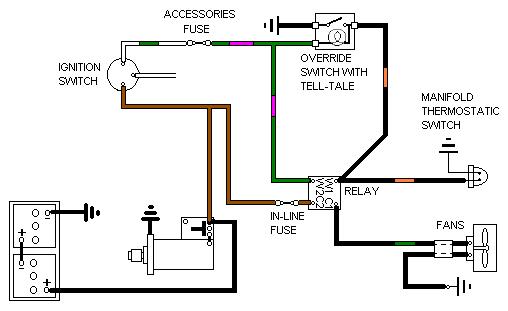
I opted to make a further modification so that the fans can only operate when the accessories circuit is powered, which means that they are disconnected during cranking which takes a significant load off the battery. Yes, they will continue to run when turning the ignition key from 'run' to 'accessories', but still will stop when the ignition is turned fully off and the key removed. The green fused ignition feed to the relay is removed and a green/pink fused accessories feed connected instead. Note that if you have an override switch, and if that has a tell-tale, then you need to make the same change at the switch. The easiest way of doing both of these is to take a piggy-back feed off the heater switch (which is powered from the accessories circuit) to the override switch for the tell-tale, then extend that wire into the engine compartment to the relay.