by Herb Adler 5243 3409
SNIPPETS
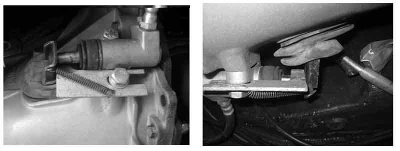
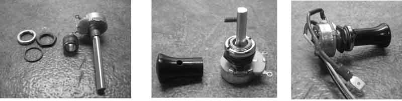
Throwout bearing protection
I was a bit concerned about throwout bearing wear, so I made this gadget, which limits the distance that the lever arm can move, so that the bearing is not continually in contact with the clutch pressure plate.
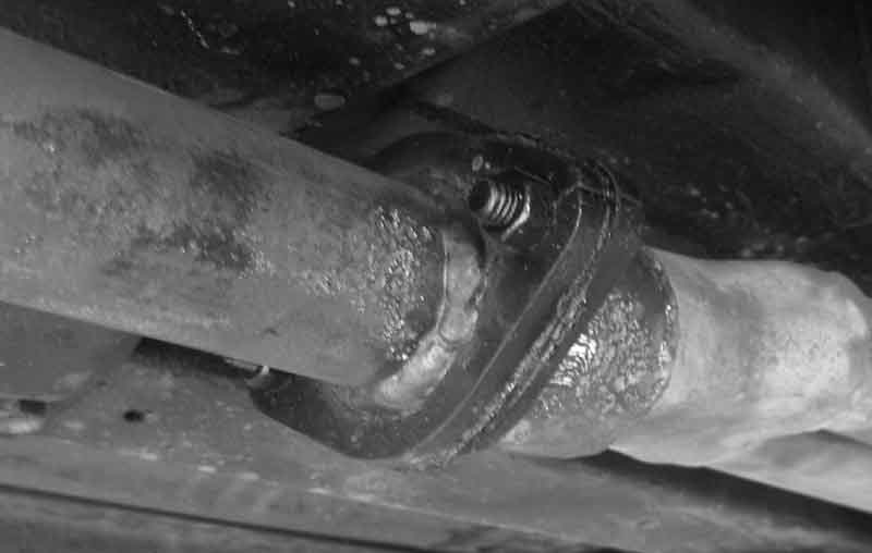
Exhaust
I have extractors and the exhaust system was a single piece from the engine to the rear tail pipe. This made it impossible to remove the engine, so the pipe had to be cut. To keep cutting and welding the pipe was not on, so I had these flanges fitted.
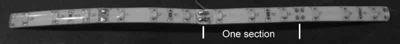
I have been playing with upgrading the lighting of the gauges in the BB, using green LEDs (light emitting diodes). These LEDs are brighter and use much less power than conventional globes. I used LED strips, which are about 8mm wide and have many individual LEDs and current limiting resistors on them. They come by the metre and one can cut them to a desired length, providing a section contains 3 LED chips and their corresponding resistor. Experimenting shows that there will be a significant improvement. Because LEDs use so much less power the existing brightness adjusting rheostat cannot be used, so I developed a replacement, mounted in the original bezel.
LED strip
Part of the upgrade consists of painting the inside of the gauge cases gloss white, which in itself improves the brightness.
New rheostat
The new rheostat is a 500 ohm 3w wire wound potentiometer, epoxied into the bezel from the original rheostat. The shaft is cut to length and a hole drilled and tapped to 1/8”, for the knob locking grub screw.
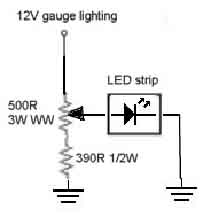 The circuit for the new rheostat is a 500 ohm 3 watt wire wound pot., with a 390 ohm ˝ watt resistor to ground. This resistor is required to be able to completely turn off the LEDs, as even a very large (100k) resistor in series with the LEDs still turns them on, slightly.
I positioned two single sections of LEDs, as shown, inside a white painted case, using automotive grade double sided tape.
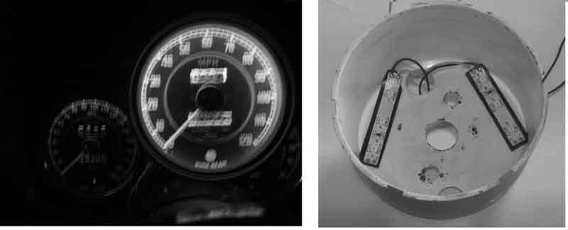
Comparision, LED and standard lights LEDs in case
‘scuse the burriness, I couldn't hold the camera steady long enough.
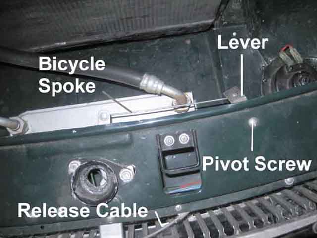
Bonnet release cable
Well, early on I had to fit a bonnet release cable. I had two problems. One, the “slam” panel had a catch that required the cable to come from the left side of the car, but there was no hole on that side of the dash for a cable, although there was one on the right side. Two, I didn't relish having to lie across the seats every time I wanted to open the bonnet. So how to overcome these issues? Using a nice chromed metal piece I had lying around (from a bike pack carrier) I fashioned a lever, which I mounted on the panel. I made a cable locking screw, by drilling a hole through a screw and using two nuts to clamp the cable. The other end, that went to the catch, was a simple bike spoke.
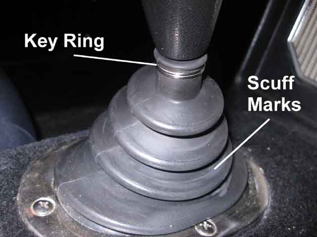
Shift lever boot
When I replaced the shift boot, with a brand new one, the new one was flat. When shifting gears the rubber corrugations would rub against each other and make an annoying squeak. The original boot wasn't flat, but extended to nearly the top of the shift lever. Pulling the new boot to the top didn't work, as it wasn't tight enough to stay. So I fitted a key ring, which was a tight fit, and a cow to get on, and now the boot is locked to the top, no more squeaks. A fellow club member told me that the new boots tended to wear out quickly, at the places where the rubber came into contact with the next corrugation, so I probably extended the life of the boot as well.