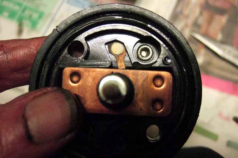
4-Cylinder pre-engaged:
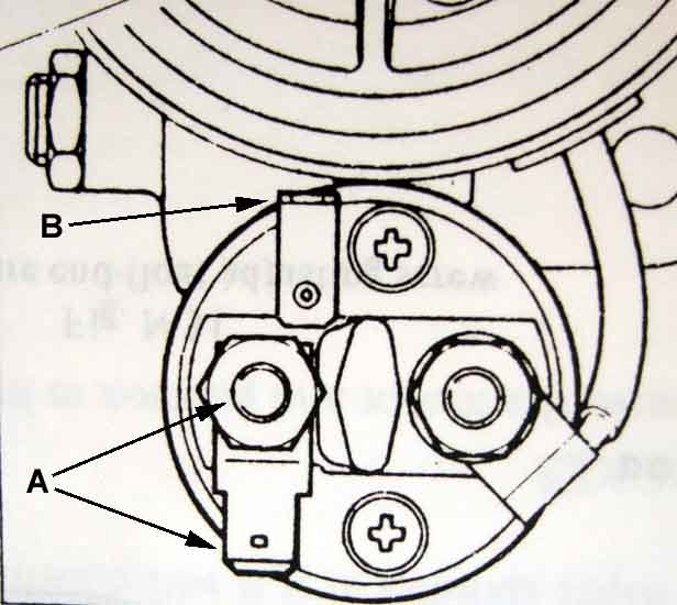
Earlier 2M100 pre-engaged starter on 18Gx engines: A - battery cable stud and large 12v spade. B - standard-sized solenoid operate spade. No 'boost' contact:
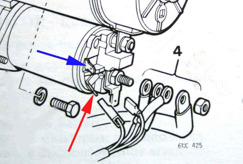
Later 2M100 pre-engaged starter on 18V engines, V8 starter is similar: Everything bracketed as '4' goes on the stud - battery cable and two or three brown wires. There should always be two thick brown wires (from the alternator and to the rest of the cars electrics) and an optional standard-gauge brown wire which goes to the alternator for voltage sensing. The large spade (9.5mm) on the stud is for compatibility with earlier models. The standard-sized spade (6.3mm) lower left (red arrow) is for the solenoid operate wire which is a thick white/brown or white/red (or possibly a brown/white, diagrams vary). The small spade above that (4.8mm) is for the coil boost wire (rubber bumper 4-cylinder and all V8s) which is a standard gauge white/light-green (white/light-blue on V8). (Leyland Workshop Manuals)
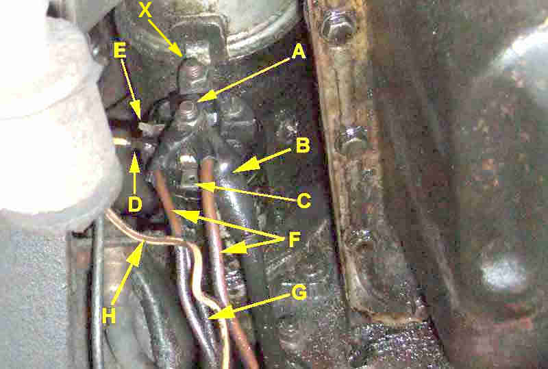
In practice: 'A' is the battery cable stud, 'B' the battery cable, 'C' the large spade for brown wires as used originally. 'F' are the brown wires to the cars electrics and the output from the alternator, 'G' is the additional smaller gauge wire to the alternator on cars that used battery sensing. 'D' is the solenoid operate terminal and 'H' the solenoid operate wire, 'E' is the coil boost terminal only used on rubber bumper cars and V8s. 'X' is the output stud of the solenoid with the nut clamping a copper strap leading into the motor:
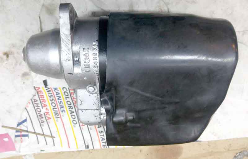
Rubber boot over the starter connections from May 72: (Ahmed EL Abasiry, Canada)
V8 specifics:
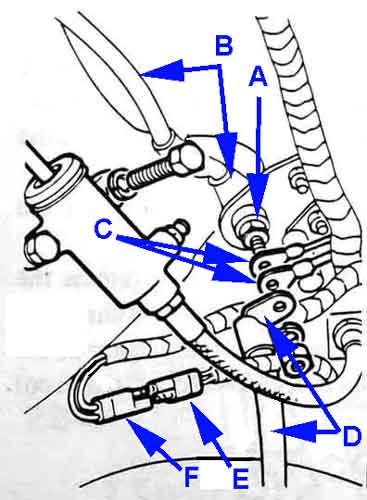
The intermediate connection in the V8 battery cable: 'A' is the insulated stud on its mounting plate bolted to the toeboard; 'B' is the cable from the battery mounted to the top part of the stud; 'C' are the two brown wires from the harness; 'D' is the short length of battery cable to the starter solenoid stud; 'E' is the 2-pin connector on the short sub-harness going to the solenoid spades; 'F' is the other half of the 2-pin connector on the main harness tail. This connector can only be assembled one way (and is the same as the cooling fan connectors): (Leyland V8 Workshop Manual Supplement)
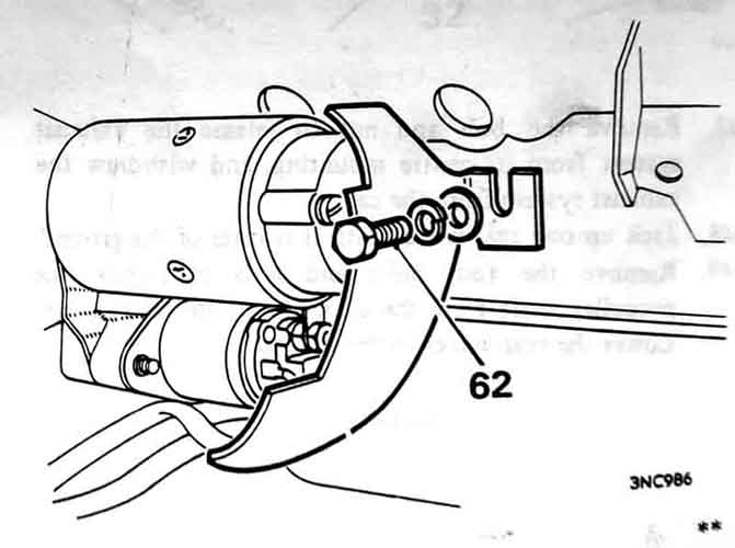
V8 starter heat-shield, the correct item is moulded heat-resistant material with a metal bracket riveted on. Not shown but the off-side exhaust down-pipe is immediately to the right of this, but it also passes underneath so although the end of the solenoid and starter are shielded the lower body of the solenoid isn't. The heat eventually weakens the ability of the solenoid to hold in once it has connected power to the motor and battery voltage has dropped, and it chatters as if the battery is flat. When Vee came to me it was just a tin sheet which wouldn't have helped much with keeping heat off the solenoid, with one of the bracket rivets broken away so with relatively light pressure it could by pushed against the battery cable stud shorting it out! (Leyland V8 Workshop Manual Supplement)
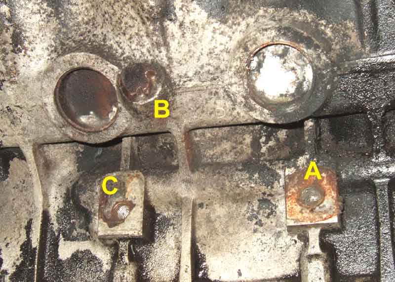
At least one person has said his block doesn't have a tapped hole for the fixing bolt, but both my original and an engine from elsewhere both have it. 'A' is the lower mounting point for the engine mounting plate, 'B' is the block drain plug, and 'C' is the hole for the heat shield:
Vee's replacement starter: A copper bar bridges the two stud contacts A and B when the solenoid operates and is supposed to connect power to the small coil boost contact as well. But that contact (arrowed) is bent back ...
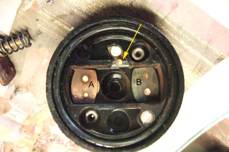
... so that the copper bar misses it altogether, and has obviously never worked on this starter that I fitted in December 1999 as a newly rebuilt item:
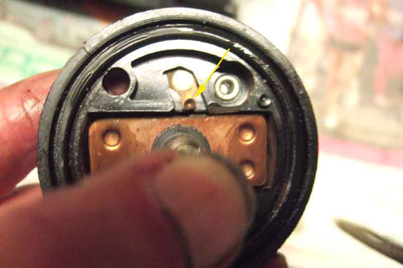
The coil boost contact is straightened and positioned so that the copper bar touches it and pushes it down just before it reaches the two studs:
