Fixings Pickup/strainer Overflow prevention Filler caps
For those worried about ethanol this tank has been on Peter Mitchell's 1978 since he got in 1988, it had done 34k by then so is probably original, and shows no signs of internal corrosion:
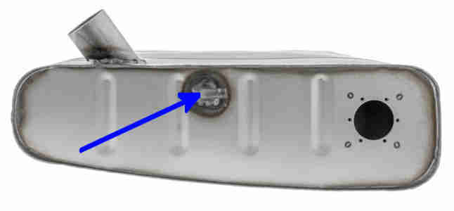
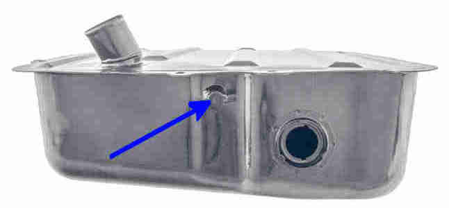
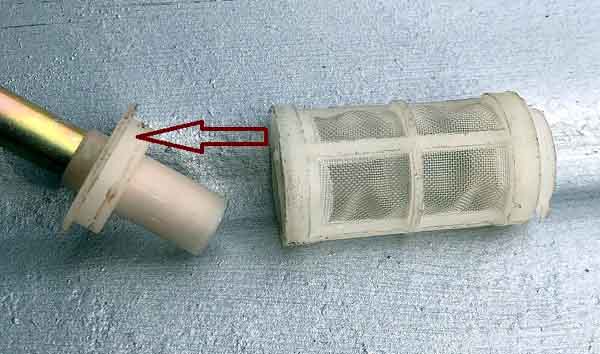
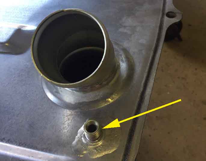
Later 12.7 gall bolted tank from March 65 with locking-ring sender, fuel outlet prior to August 1976 arrowed, after that it was incorporated with the sender:
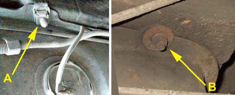
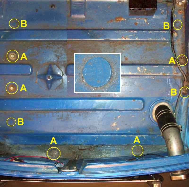
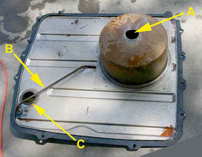
The bolts into the captive nuts are at A, and the welded studs are at B, with a stud enlarged in the inset:
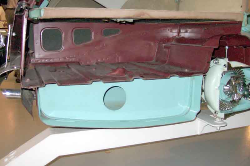
Second baffle, left-hand side:
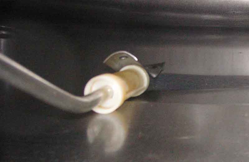
From Albert Ross - detached strainer on a combined sender and pickup, he 'welded' it back together with a soldering iron to melt the plastic, in preference to using an adhesive which would need to be chosen very carefully:
From Richard Massey - a replacement tank from the MGOC with no baffles and the strainer wedged under the bracket, even though there appears to be a hole for the tube to pass through. Interestingly with the strainer lying on the bottom instead of standing up there is probably an extra inch of usable fuel, which considering the size of the base could be a few litres. However lying down like that it is going to be picking up any water lying on the bottom, although that's only likely to be a problem if the car is unused for a long time and something has allowed water to collect. Forget ethanol - that ABSORBS water and it will pass through the engine and the only effect would be an unnoticeable reduction in fuel economy. Non-ethanol fuels are more likely to get water separation, and as liquid water it could stop the engine running or cause damage:
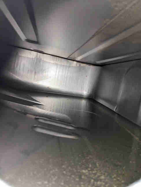
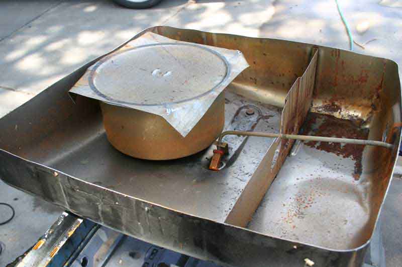
The chamber removed from the lid and lying in the bottom of the tank, also shows the remaining baffle and the pickup:
Breather port (in place of a vented cap) on top by the fuel filler: (Bill Etter)
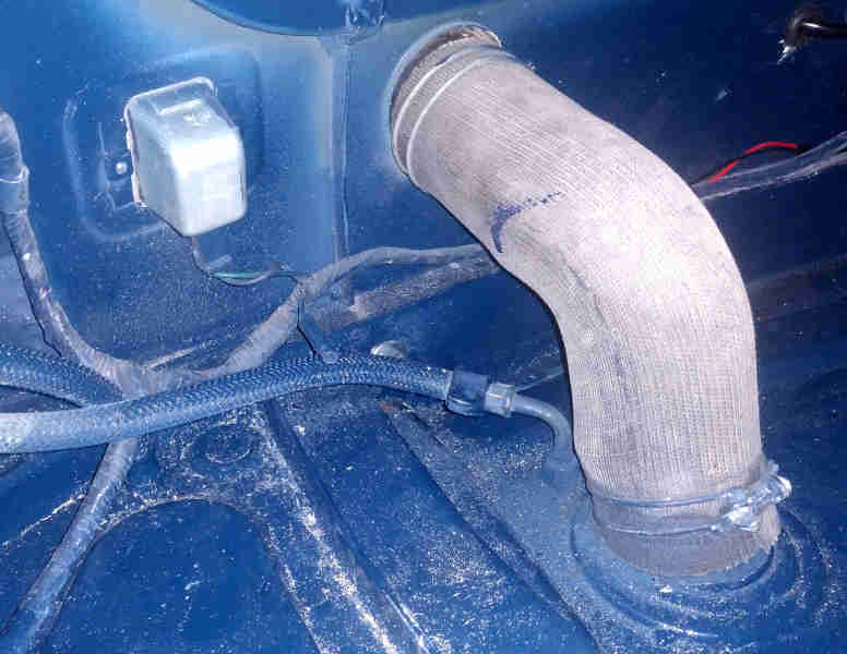
Connection to the tank vent: (Bill Etter)
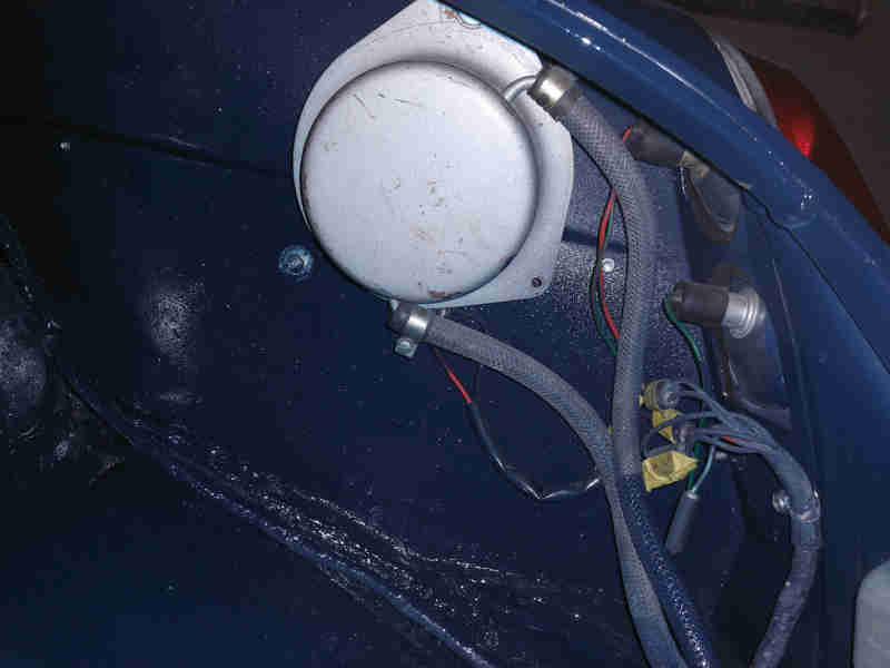
Up to the separation chamber (lower connection so fuel can run back to the tank): (Bill Etter)
And from the upper connection through the boot floor to the pipe leading to the charcoal canister: (Bill Etter)
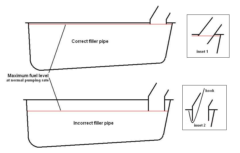
Filler pipes, correct at the top (see 'C' here as to how it should be inside), incorrect at the bottom. For each inch the filler extends into the tank you are losing about nine litres or two gallons of capacity! Note that if the filler pipe goes into the top of the tank at an angle it is the highest point of the bottom of the pipe that will determine how much lost capacity there will be, not the lowest point (see inset 1). If the tank is installed with the boot floor and foam seal covering the top of the tank, then with the filler neck and joining hose removed a length of stiff wire bent into a hook adjusted in length until the loop of the hook is just held below the bottom of the filler by the top of the hook being on the underside of the tank, will give you a good idea, see inset 2:
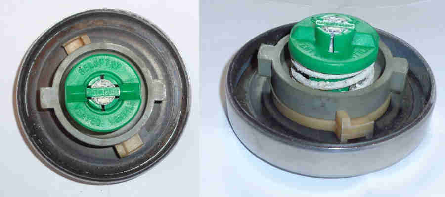
The green part with the - hefty! - spring underneath is attached to the barrel of the lock so the spring is trying to pull the barrel through the cap at one end and pressing down on the grey part at the other. That grey part has lugs (shown here in the fitted position) that latch onto the filler pipe, pulling the seal under the outer part of the cap down onto the neck of the filler pipe. Fitted I can get my finger-tips behind the cap and pull against spring pressure, which is lifting the cap seal away from the filler neck. It may be that with a depression in the tank the reverse happens in that the grey part is pulled back, which takes the pressure off the seal, so letting air in. However it takes quite a lot of force, and the depression will be acting on other parts of the cap and seal as well, the outer part of the cap as well, so I'm still pondering. If not that then there must be another valve and spring inside the cap somewhere (like the radiator cap), and videos do show those with valve and spring much smaller.
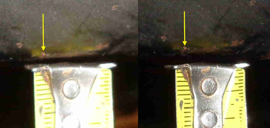
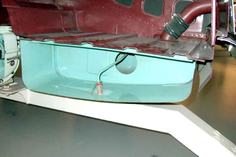
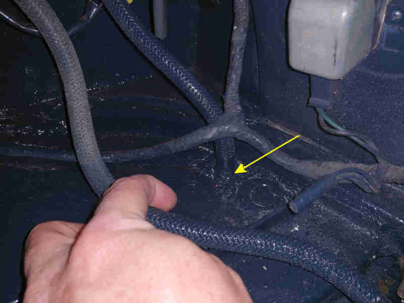
Tape measure propped up under the lowest part of the tank, a gallon pumped out, then put in the boot so the weight is as before. Only about 2-3mm difference as indicated by the little rust-spot arrowed: