

Notes:
- 12v is switched for both normal and fast speeds.
- Earth (black) at the motor is used for both running and parking, the green at the motor is used for parking only.
- Red/light-green is 'slow' speed, blue/light-green is used for 'fast' speed, brown/light-green is used for parking.
- For 1971 models until the end of chrome-bumper production and all V8s the wipers (and heater fan and electric screen washer) were powered from the accessories circuit via an in-line fuse under the fusebox. This has a white/green wire from the ignition switch and a green/pink to the wiper switch and motor.
- 1978 and later UK models cars have two sub-divisions of the green circuit with their own in-line 35 amp fuses under the fusebox. Both are supplied by the white/brown (ignition relay) circuit and one feeds the heated rear window, indicators, heater fan and tach, the other feeds the electric cooling fan. Which leaves the original green circuit fuse (2nd one up in the four-way fuse block) feeding things like reverse lights, stop lights, washers, wipers, and circuits associated with the seat belt warning lamp and time delay buzzer.
Later parking system (2-speed round motor) - Logical representation:
Note 1: The above diagrams show the later (round) 2-speed motor. I have received information from one source indicating that the rare 67 GT single speed round body motor has the later parking arrangement, and from another source that theirs has the earlier. You have been warned!
Note 2: From 1971 for the remainder of chrome bumper production and all V8s the electric washers (and wipers and heater fan) were powered from the accessories position of the ignition switch via a white/green to an in-line fuse under the fusebox, and then via a green/pink. 4-cylinder cars reverted to green (ignition) from the main fusebox with rubber bumpers.
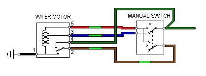
Physical representation: 'Switched off but not yet parked':
The rocker switch has internal connections that are not brought out to spade terminals.
For the column switch in the off position the brown/light-green (park) and red/light-green (slow) wires are connected together. In the slow position the red/light-green and green (12v) wires are connected together, and in the fast position the green (12v) and blue/light-green wires are connected together. All of which the toggle/rocker switch does as well, but in a more complex fashion.
Hover over a wire to confirm the colour

Wipers running at slow speed. 12v from Green through manual switch then via Red/Light-green to motor. Motor parking switch is disconnected.
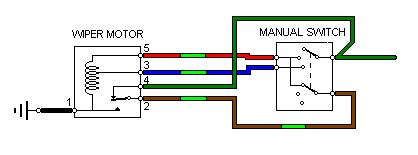
Wipers running at fast speed. 12v from Green through manual switch then via Blue/Light-green to motor. Motor parking switch is disconnected.
Wipers switched off but not yet parked. 12v from Green through motor parking switch, from motor to manual switch on Brown/Light-green, through manual switch (off) then to slow-speed winding of motor on Red/Light-green.
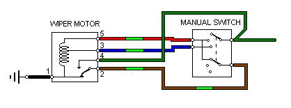
When the wipers reach the park position the motor park switch changes over and connects an earth
via the Brown/Light-green, the manual switch (off), Red/Light-green to the slow-speed winding, effectively shorting it out and rapidly stopping any residual movement of the wipers. The wipers are now switched off and parked.
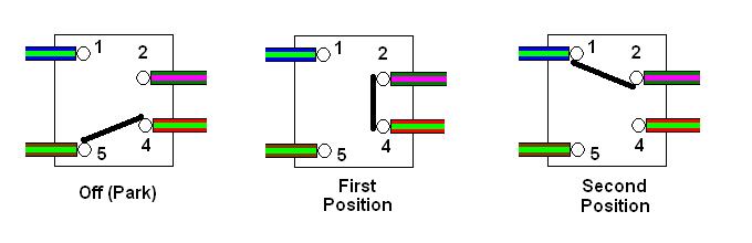
 Early toggle switches have pins 1, 3, 5 and 7 connected together internally and brought out to spade terminals which are unused.
In the off position contacts 2 (park, brown/light-green) and 6 (slow, red/light-green) are connected together to allow parking.
In the slow position contacts 4 (12v, green) and 6 (red/light-green) are connected together.
And in the fast position contacts 4 (12v, green) and 8 (blue/light-green) are connected together.
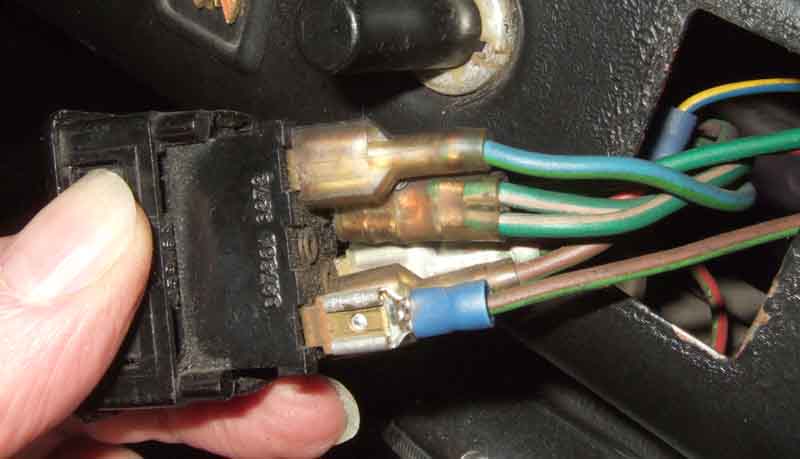
In the off position contacts 5 (park, brown/light-green) and 4 (slow, red/light-green) are connected together to allow parking.
In the slow position contacts 2 (12v, green/pink) and 4 (red/light-green) are connected together.
And in the fast position contacts 2 (12v, green/pink) and 1 (blue/light-green) are connected together.
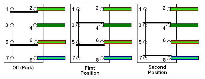
The 12v supply wire (green, green/pink from 1971) is connected to terminal 4.
The slow-speed wire (red/light-green) is connected to terminal 6.
The fast-speed wire (blue/light-green) is connected to terminal 8.
The 12v supply wire (green/pink) is connected to terminal 2.
The slow-speed wire (red/light-green) is connected to terminal 4.
The park wire (brown/light-green) is connected to terminal 5.
Note that although the terminals are numbered top to bottom with the switch the right way up and horizontal to the spade they refer to, the numbers themselves are upside down:

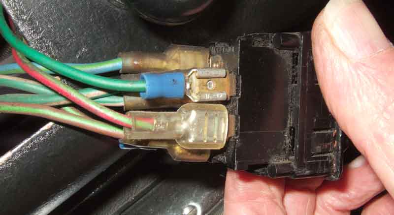
There are two factory green/pinks in one spade connector on terminal 2. This shows a second brown/light-green piggy-backed with the existing brown/light-green on terminal 5 ...
... and a green piggy-backed with the green/pinks, both as part of a Smartscreen installation:
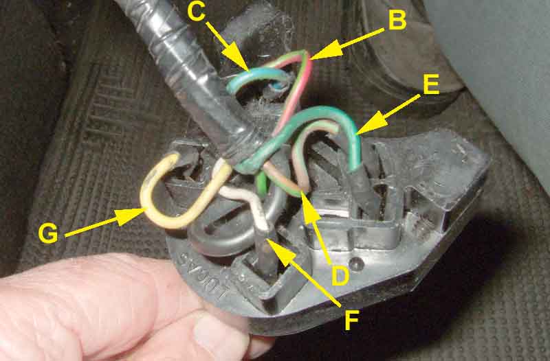
Internal arrangement of the column switch:
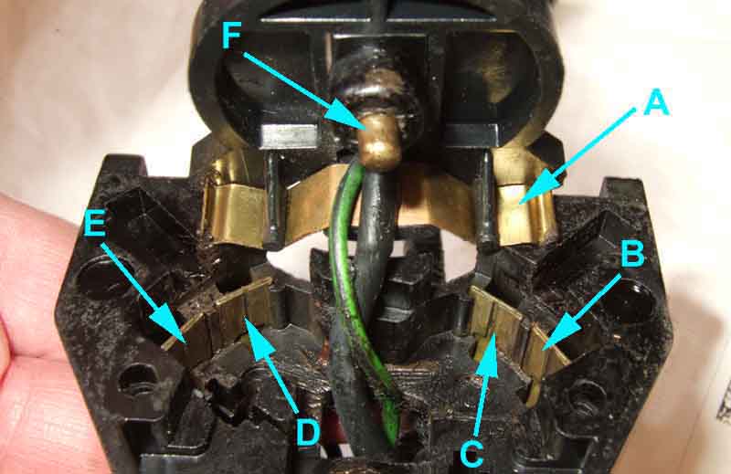
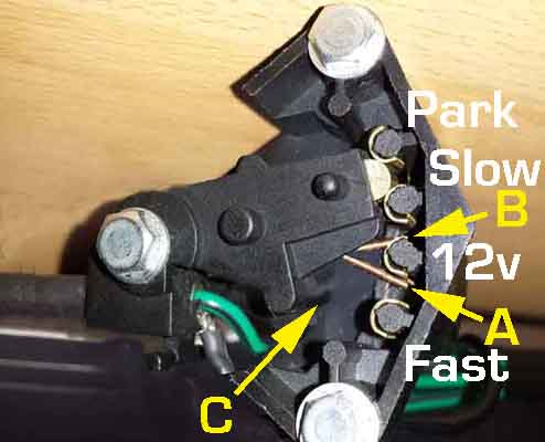
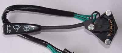
Back of the switch: B - red/light green slow speed; C - blue/light-green fast speed; D - brown/light-green park; E - green 12v; F - white ignition feed for overdrive; G - yellow to overdrive:
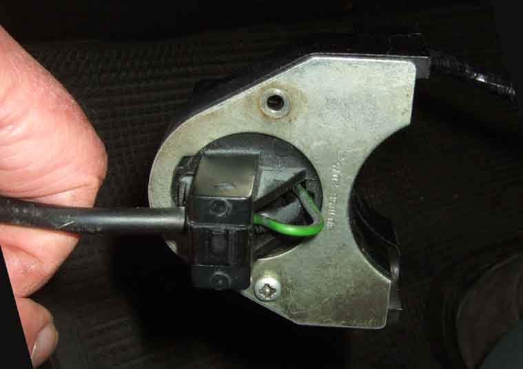
Front of the switch, two screws (one already removed) in the cover:
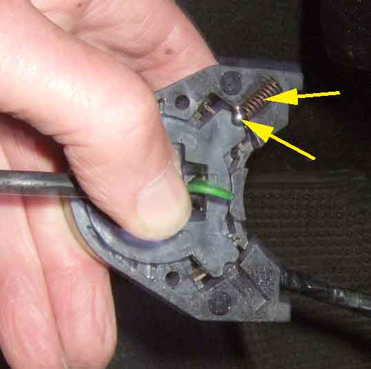
Cover removed, two detent balls and springs arrowed (lower pair removed):
Inside the switch: A - bridge to connect the various contacts together; B (slow) to D (park) - park/off; B (slow) to E (12v) - slow speed; C (fast) to E (12v) - fast speed. F is the sprung detent for the OD switch:
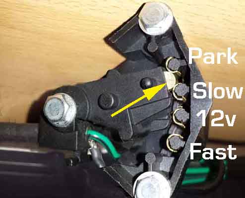
The moving portion of the switch has a brass roller (arrowed) that bridges adjacent pairs of contacts in each of the parked, slow and fast positions. The switch is shown in the parked position bridging the Park and Slow contacts. The switch is shown in the RHD orientation, rotate the image 180 degrees for LHD.
Flick-wipe, switch now BAU1020:
Basically the same switch, but the stalk is allowed to move down past the Off position. There is also a wire spring wrapped around the stalk pivot, with two arms to make the flick-wipe connection.
With the switch in the Off, Slow or Fast positions both wire spring arms A and B are resting against the 12v contact.
But with the stalk pulled down past the Off position, the roller moves away from the Slow contact to break the connection between the Park and Slow contacts, then cam C passes spring arm A and moves spring arm B away from the 12v contact and onto the Slow contact. With spring arm A still on the 12v contact the motor is powered at its slow speed while the stalk is held down. When the stalk is released spring pressure returns it to the Off position, with both spring arms resting against the 12v contact. The roller reconnects the Park and Slow contacts, and the motor parks as normal.
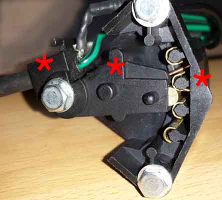
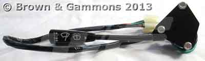
Switches from a number of sources have been assembled incorrectly - maybe with the change of part number to BAU1020 - as shown by the asterisks above: The stalk is above the pivot instead of below, the cam to operate the spring fingers is also pointing upwards instead of down, and the wire spring fingers are around the second contact down instead of the third. At the time of writing Moss, Brown & Gammons and Midland Sports and Classics are correct in that the stalks are below the pivots as can be seen here:
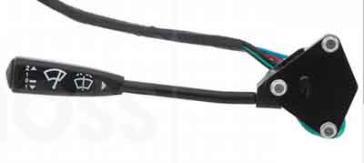
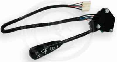
Whereas (again at the time of writing) these (Motaclan/Leacy, ANG and Auto Electrical Supplies) are all incorrect as the stalk is above the pivot:
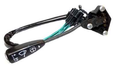

You can see by the logos on the stalk end that it is not a case of these switches needing to be installed on the other side of the column, or being operated in the other direction. Another thing to note is that all the correct items have a cover over the contacts on the side facing the driver, whereas the incorrect items do not. The upshot is that the stalk has to be moved in the opposite direction to that expected, and that indicated by the logos.
September 2019:
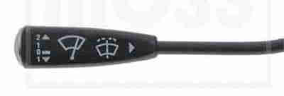 The above Motaclan/Leacy, Moss and Brown & Gammons and Auto Electrical Supplies links are currently all showing the stalk above the pivot i.e. incorrect, only MS&C are showing it below (ANG Classic Car Parts are not currently showing it). They all quote the same part number, all show the same logo showing the stalk should be lifted for speeds 1 and 2 and depressed from the off position for flick-wipe. (Moss)