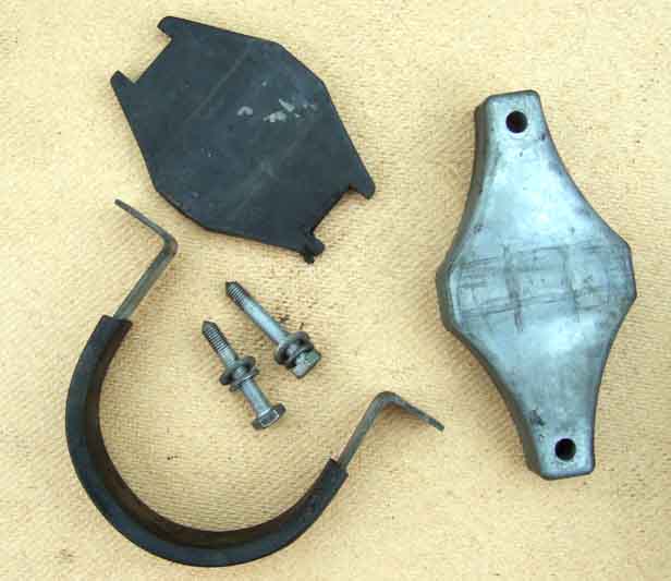
First thing is to remove the U-strap securing the motor. There should be a plastic/rubber sleeve between the strap and motor, and a metal backing-plate behind the motor, with a rubber insert between the plate and motor:
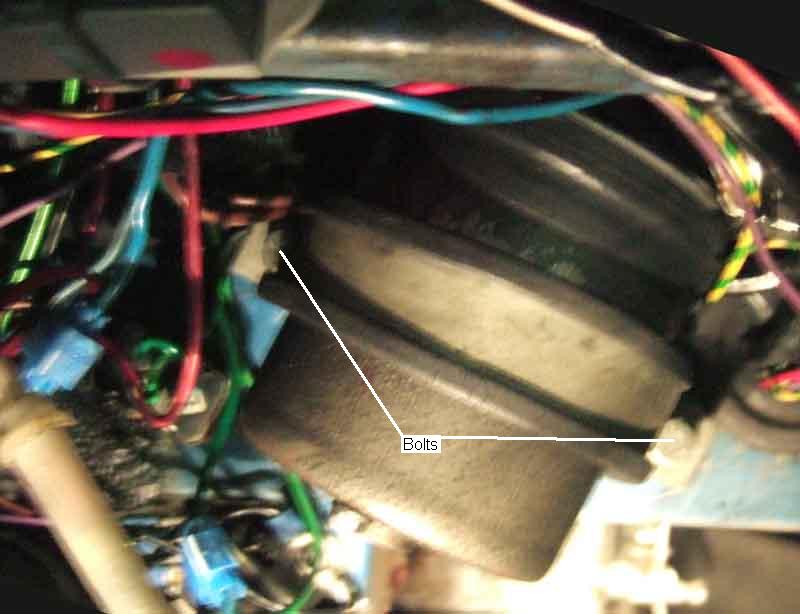
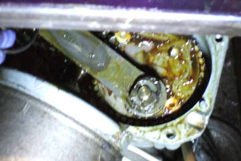
This allows you to orientate the motor to be able to remove the harness plug from the motor for electrical tests (but be aware that 12v on a meter from an unplugged connector could still have bad connections further back that will prevent the motor running) and also makes access to the four gearbox cover screws easier. Remove these to expose the gears and 'con-rod' that connects the large gear crank-pin to the end of the rack:
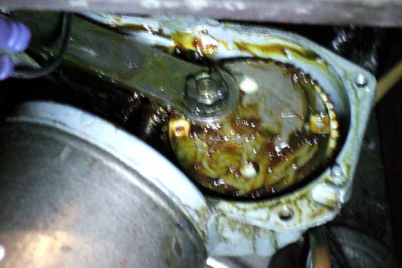
If you lift the blades off the glass, turn the wiper switch on, then turn the ignition on and off while watching the crank pin, you can position it to be lower down and so easier to access:
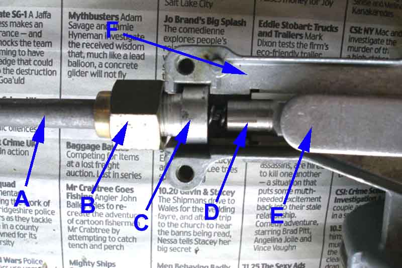
A - rack tube; B - nut; C - tube locator; D - spiral rack with end connector; E - connecting rod; F - gearbox casing. The nut is behind a swage on the end of the tube and screws onto the locator to clamp the tube to it. The tube locator slots into the gearbox casing: (Mike Howlett)
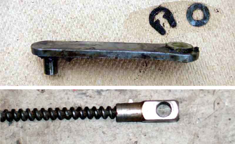
The connecting rod (top) is secured with a spring clip to a crank-pin on the large gear. Lever the clip off (with your thumb over it to stop it pinging off somewhere) and remove the crinkle washer and connecting rod. Note there should be a larger shim under the con-rod on the crank pin. The pin on the rack-end of the connecting rod is fitted into a hole in the rack cable connector (bottom):
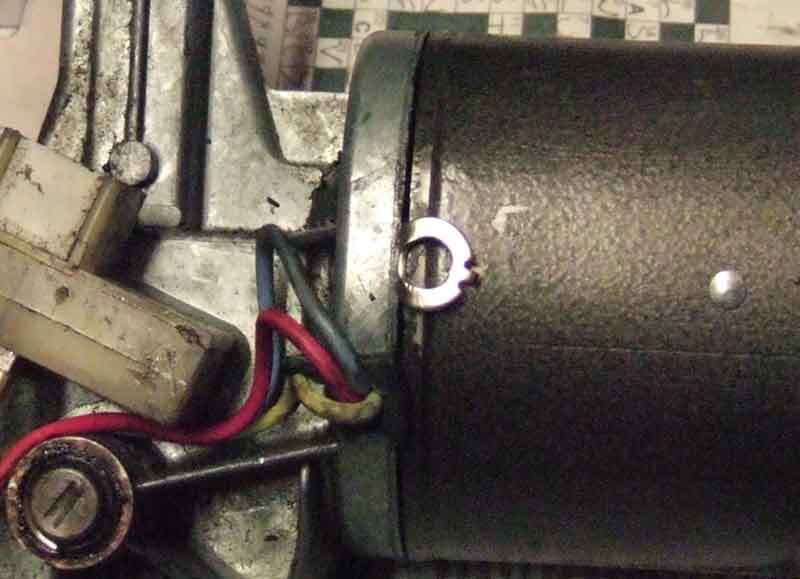
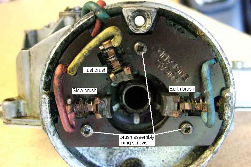
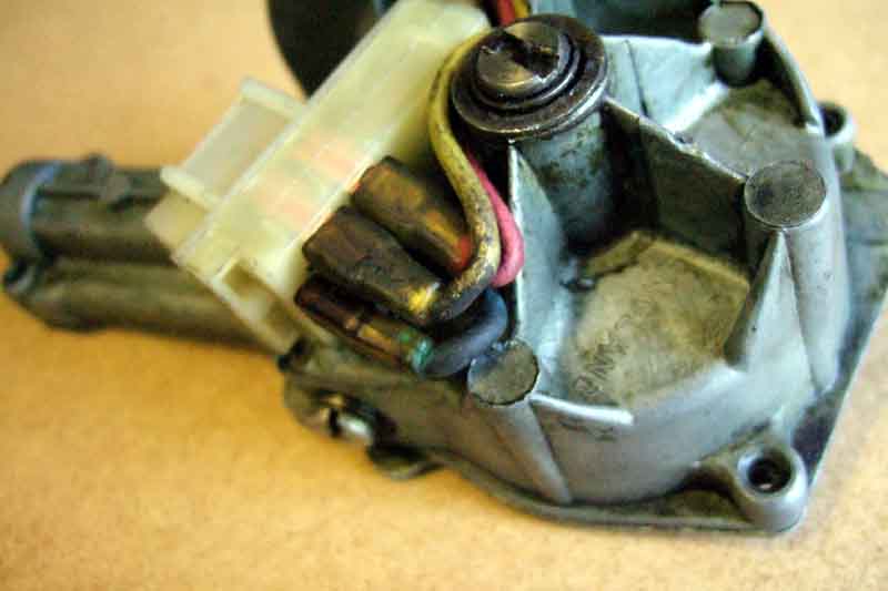
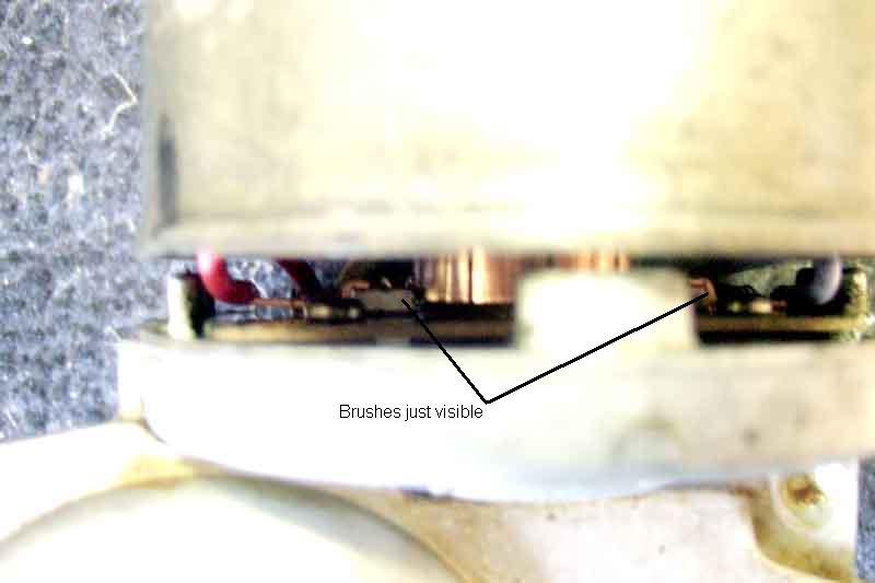
The rack and its tubing can now be lifted out of the gearbox casing and the motor unit removed from the car. Unless you are going to be working inside the gearbox it is a good idea to refit the cover to stop the grease going everywhere. Remove the two long bolts from the back of the motor and separate the motor from the gearbox carefully, to expose the brushes. Note the slow-speed brushes (red and blue wires) are diametrically opposed to each other and the fast-speed brush (yellow wire) is offset, and has a narrower running surface. The blue brush is the earth connection common to both speeds, 12v being switched between the red and yellow brushes to change speeds:
Note also how the wires connect to the connector block:
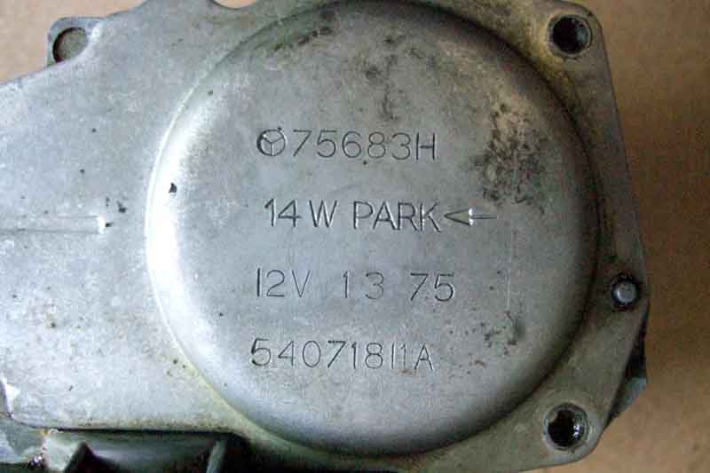
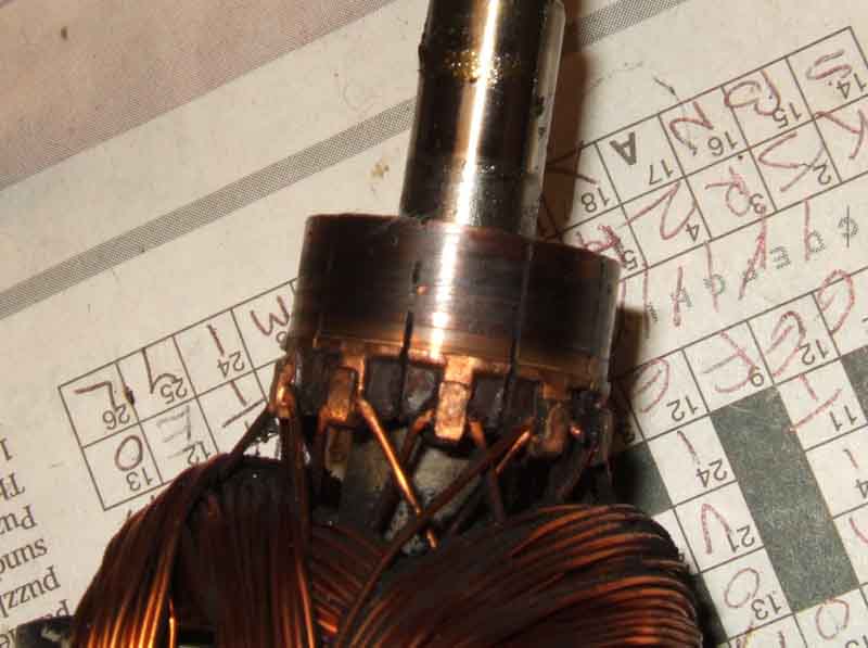
'14W' is the motor type. 'Park' and the direction of the arrow shows where the crank pin parks, in this case closest to the rack tube putting the blades on the right. Despite being what appears to be the original motor (manufactured week 13 of 1975) and having done over 200k miles ...
... the commutator shows no apparent wear:
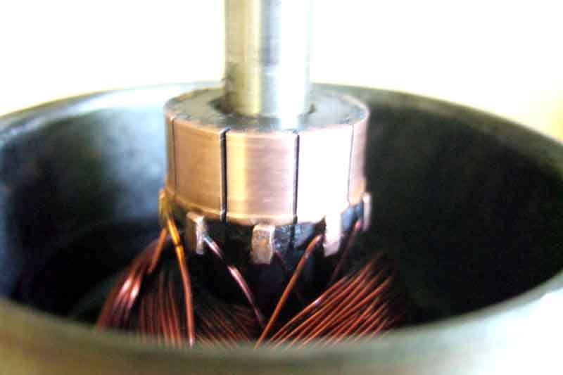
No need to undercut the insulation between the segments, I just ran the tip of a craft knife through the slots carefully to clean them out and polished the commutator:
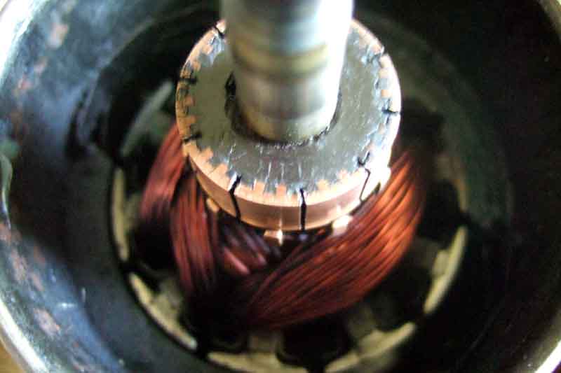
Bee's was exactly the same - just needed a clean and a knife blade run through the slots to clean them out - this is the 'before':
I also pulled the rotor out of the casing (which requires quite a bit of force to overcome the magnetic attraction so make sure you have a good hold on it), cleaned the surfaces of it and the magnets on the inside of the case, and lubricated the felt bush at the bottom of the bearing in the motor case with light oil. When reinserting the rotor the magnets will pull it to one side, but it isn't too difficult to lever it against the magnets to get the end of the shaft aligned with and inserted into the bearing. Make sure the rotor rotates smoothly, although because there is no support for the top of the shaft at this point this is easier said than done, but possible. It will bind if the rotor is tilted over so that one side of it is up against a magnet, but should rotate easily if you can get a relatively equal clearance between rotor and magnets all the way round:
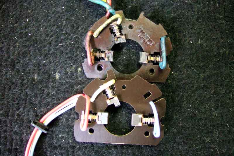
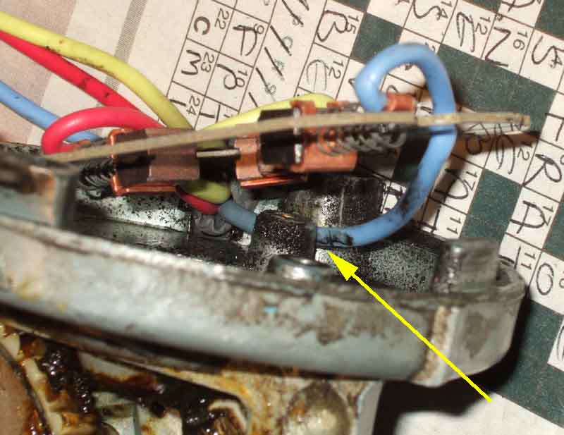
Vee's old (top) and new brush assemblies. Plenty of 'meat' on the slow and particularly the earth brushes (they may not be original), although most of the narrow section of the fast brush has gone, more from mechanical wear than electrical as I rarely have had to use fast speed. The brushes were still close enough to stop the end of the commutator fitting straight back in, but only just, and so not much spring-pressure to make a good electrical contact. Note there is no curve on the face of the new brushes. Remove the old and fit the new brush assemblies, being careful to get the wires on the correct spades of the connector. The blue wire runs in a slot inside the gearbox, make sure it sits in the slot and doesn't get trapped between the brush assembly and the casing. The grommet needs careful work with a screwdriver to work it into the slot in the gearbox casing before attaching the motor:
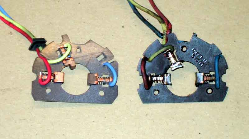
Bee's old (left) and new brush assemblies, if anything worn more than Vee's. Interestingly neither Vee's nor Bee's brush set had grommet, but both new ones did. However it was only when reviewing this picture that I realised something else. Whilst the brush material itself is considerably longer on the unworn new item, the springs aren't pushing the back of the brushes anywhere near as far out as the old springs are. So unless they work out as they are used, only a small amount of wear will need to take place before these stop working properly as well. Looking at Vees above that is similar, but not as pronounced:
When fitting the new brush set make sure the blue wire is positioned between the screw boss and the side of the gearbox casing, and doesn't get trapped. It's the earth wire so shouldn't cause an electrical problem, but it will affect the alignment of the brushes:
Reassembling the motor to the gearbox. Hold the gearbox so the motor is uppermost and pointing vertically downwards, such that the end of the comm is pressing lightly on the sides of the brushes. Use a screwdriver to pull the slow or earth speed brush back against its spring, the end of the wire where it sticks through the crimp and is soldered is convenient for this. Because the new brushes have flat ends and not curved they have to be pulled back further than is first apparent. This will allow the comm to drop a little bit further past the pulled-back brush, which when released should now rest on the surface of the comm at its very end. If it doesn't try doing the other brush first. When one is located do the other main brush, and finally the fast-speed brush. You should now be able to carefully push the motor and gearbox together. Make sure all three brushes are resting on the cylindrical surface of the comm and are not trapped by its end before applying pressure:
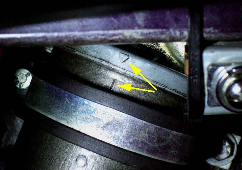
Twist the motor body so the bolt holes in the motor and gearbox casing line up - you may have to pull the two apart a little way to do this (but not so far as to release the brushes!) - and insert the motor casing screws. Note the alignment marks on the gearbox and motor casings:
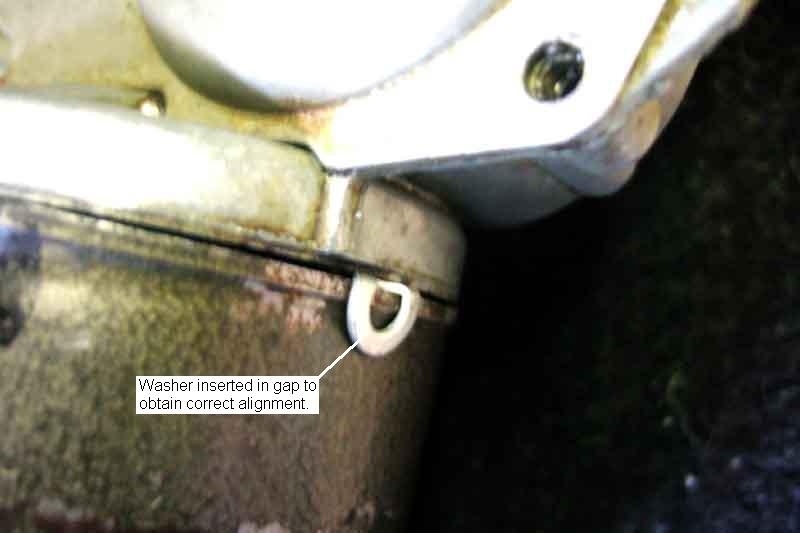
At this point it is absolutely vital to test the motor before final reassembly to the rack. This can either be done on the bench with flying leads, or by plugging the harness connector into the motor whilst supporting the motor in the footwell. The former is preferable, as I shall show. I used flying leads and immediately noticed that the motor didn't move, but I was getting lots of arcing as I tapped the leads on the motor spades. This immediately told me there was electrical continuity through the motor (there wasn't before I replaced the brushes) but something was preventing the motor spinning. If I had plugged the harness into the motor in the footwell I wouldn't have seen this, wouldn't have known whether the problem was electrical or mechanical, but the arcing and high current would have been occurring at the switch contacts which would be bad news for them. After quite a bit of fiddling about I discovered that as long as the motor bolts were slack it would run, but as soon as I started tightening either of them it would slow and as I tightened further would stall. One of the bolts had a greater effect on this than the other, which told me something was out of alignment. I tried rotating the motor casing 180 degrees relative to the gearbox but it was just the same. After a lot more fiddling, dismantling, inspection and reassembly, including slackening the large screw in the gearbox casing that supports the screwed end of the motor spindle, I discovered that by wedging a thin washer in one specific part of the casing the motor would run at full speed even when the motor bolts were fully tight. This needed quite a bit of experimentation with one or more washers around the periphery (I only inserted them adjacent to the lugs on the gearbox casing that protrude down into the motor casing to avoid the risk of them falling inside) before I landed on the best arrangement. Why this should be I don't know, maybe I have disturbed something. If I get any further problems with the motor then I think I shall have to replace the whole thing, but it's worth a try first, even at the risk of being called a DPO:
Finally I taped round the join between the motor and gearbox to seal the gap where the washer was, plugged the motor into the harness and tested again using the column switches, and reassembled to the rack, which is the reverse of removal but a lot more of a fiddle! With everything back together and a bit of water on the glass it doesn't seem much faster than before (but at least they run!), but then the glass wasn't as wet as it normally would be when using the wipers, the engine wasn't running so the system voltage was a couple of volts down, and because the new brushes are square-ended instead of being curved there is only a small contact area at the moment. Subsequently I used a watering can with rose to sprinkle water at the top of the screen while I tried the wipers at slow and fast speeds with the engine running at a fast idle, and they ran fine. It seemed to me they were faster than before, so maybe there had previously been an incipient binding that was slowing the motor a bit, which my opening it up worsened, but the washer has compensated for.
Testing Bee's motor I found exactly the same problem I had had with Vee's new brush set and that was the motor binding and running very slowly. Slackening the motor screws and tilting its case slightly freed the motor up, again exactly as before. This time determined to try and find the cause, I removed the motor case, refitted the old brush set, and refitted the motor, and it ran perfectly. Several times I had the motor off and on with both new and old brush sets and it always ran correctly with the old set, and always ran slowly with the new. The only point of contact between the brush set and the armature is between the brushes and the commutator, so there is no way they can be causing it when tilting the motor 'cures' it. It can't be the upper bearing in the gearbox casting as that is spherical externally in a spring mount so orientates itself to match the spindle. And it isn't the large screw in the gearbox casing that bears on the end of the armature spindle as I slackened that to give a clearance and it made no difference, and there is a nylon bush between the two anyway. It's a mystery, so again I resort to a washer inserted to create a gap on one side, i.e. tilting the motor relative to the gearbox. I reinstall everything, but may well investigate further when time and no imminent runs allow: