
by Michael Beswick
At first glance it may seem that the 4 bolts holding the mounts to the gearbox could be removed. Subsequent removal of the 4 cross member bolts would allow the cross-member to be lowered (supporting the gear box) complete with the ōyokeö fittings. However at least 2 bolts through the mounts into the gearbox are inaccessible and all may suffer from the rubber mounting pad expanding and covering the bolt heads.
According to John Twist's video there are 16 different ways for the assembly to be fitted! (November 2014: Now doubled to 32!) Whether due to incorrect fitting or not, most people have difficulty removing the cross-member! This is my experience /suggestions! Take particular care to mark which way round the bits go......
Mine is a 4 synchro box with overdrive on a 69/70 chassis.
To start, it is worth printing off the Moss parts diagram as it illustrates the all bits and some of the angles of fitment. The Leyland 4-cylinder and Haynes Manuals and the Parts Catalogues drawings are variously incomplete and/or misleading in respect of what parts are present, the order and the orientation. However the Leyland V8 Supplement also has a good drawing showing the assembly, additionally with the detail of the bush location in the yokes.
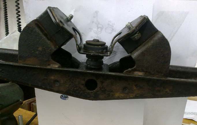
First, try to loosen the 4 main (9/16 AF) bolts that hold the cross-member to the chassis, and the 2 central ones (1/2ö AF) that hold the lower yoke to the cross-member. If your gearbox is anything like mine, it leaks, so all the adjacent nuts and bolts are unlikely to be rusty. Cross-member mounting bolts are another story and are mounted to captive nuts (or maybe a threaded plate) in the chassis rail. If it is a plate, this may move, so avoid raising or lowering the car if possible ¢or loosely fit a bolt in each side.
Assuming the bolts move, mark the position of the cross-member on the chassis rails and nip them up again.
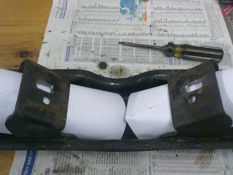
Looking at the parts diagram, note the angled brackets that take the mounts can have 2 holes in them. As the cross-member comes away leaving the mounts (and yokes) attached to the gear box, note which hole the mount was fitted to. Witness marks should show this. For which years had which parts see here. It is worth bearing in mind that after 40 years (more or less) any car could have any combination of gearbox, cross-member and mounting parts, and there could be more than one combination that lines up depending on which way each part is orientated. For example John Twist states that standard gearboxes use the front hole and overdrive the rear, but this assembly was found with an overdrive gearbox using the front holes. The bottom line is that the datum must be the engine attached to its mounts, then the cross-member parts orientated to put minimum stress on the gearbox rubbers when bolted up.
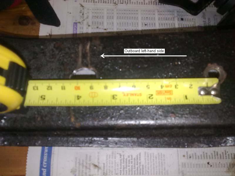
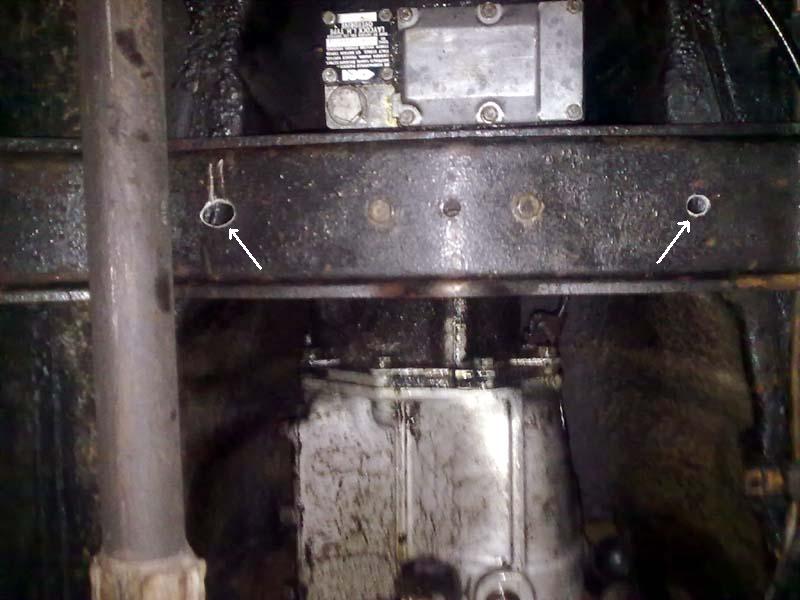
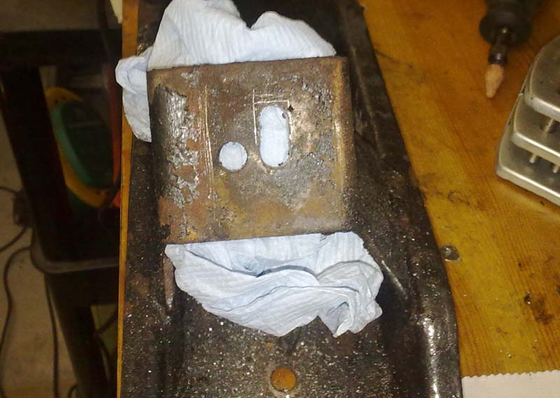
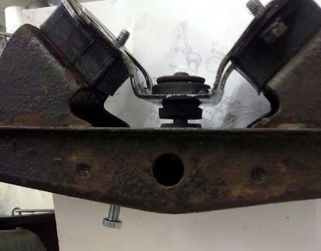
Measure and mark a point 100mm from the centre of the bolts that hold the yoke to the cross-member outwards. Drill respective pilot holes. The exhaust starts to get in the way on the left-hand side.
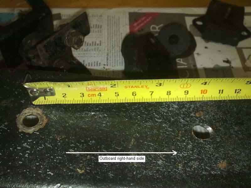
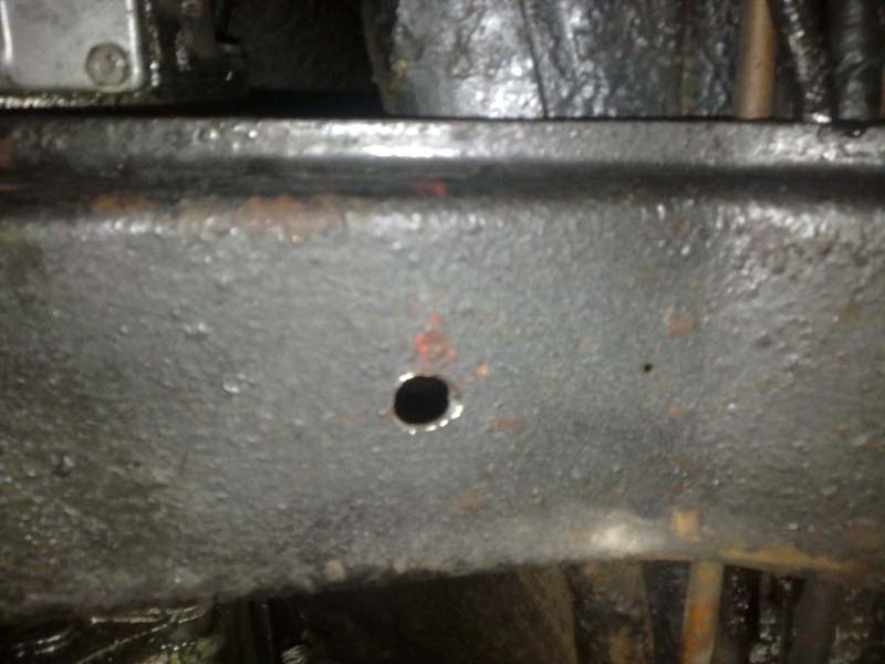
On the right-hand side enlarge the hole to 10mm, and then elongate it to about 18mm. The 18mm dimension is ōacrossö the car, the 10mm front to back of the car.
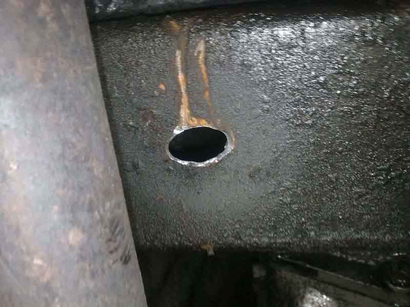
Repeat for the left-hand side but enlarge to about 22mm ōacrossö and 18mm front to back. This is not critical-the cross-member is strong, so you could just make bigger round holes. I used a Dremel to enlarge them.
It should be possible using a 250mm ╝ö extension and a Įö socket to reach the nut on the rubber mount on the right-hand side. Fit the socket after you have fed the extension bar through the hole. Note that rubber bumper cars and all V8s should have an earthing strap round the right-hand mount.
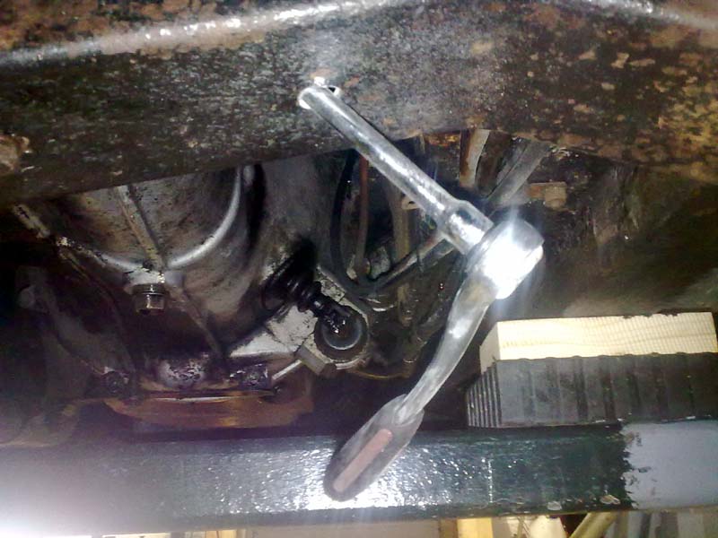
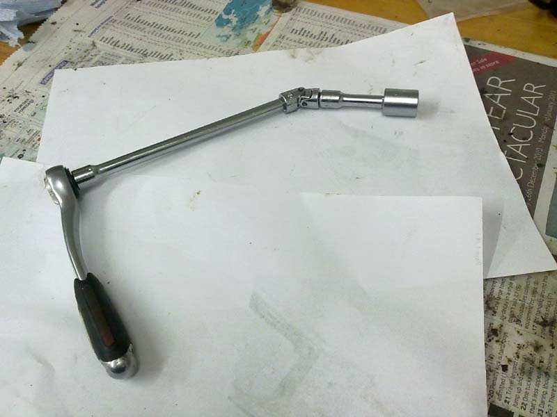
If the nut won't shift or you only have a 3/8ö drive set-make the hole bigger. For the left-hand side, the socket fits on to a 75mm extension, then a universal joint, then a 150mm extension. This allows you to work inboard of the exhaust pipe. The whole lot does move about a bit, as the U/J is turning in the hole that you drilled.
Alternatively remove the exhaust, so it becomes a repeat of the right-hand side.
And all this for two Įö nuts........(Note washer and spring washer each side) Have a break-you've earned it!
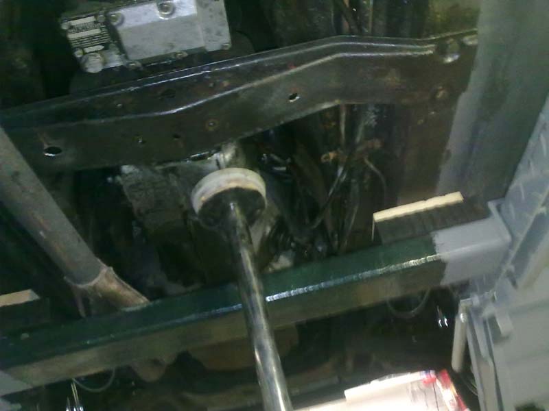
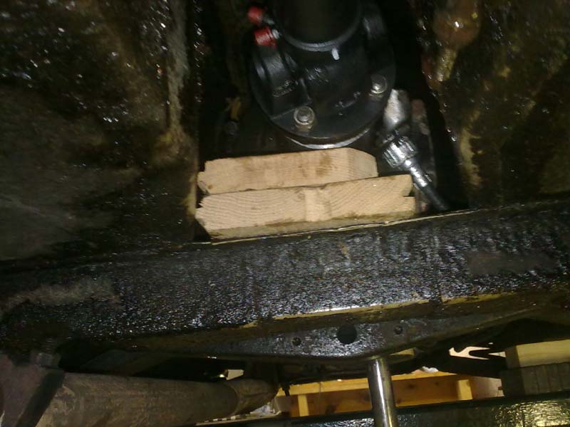
Support the gear box back end. If O/D style, blocks of wood allow you to rest the tail of the O/D on the fixed cross-member. I lifted the tail slightly to compensate for the collapsed mounts. Remember that the whole engine is now tilting slightly, so for c/b cars the clearance between front crankshaft pulley and steering rack could (but shouldn't) become an issue. (Mine is 10mm clearance)
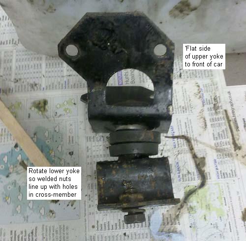
Remove the 2 bolts that hold the yokes to the cross-member. Remove the 4 bolts holding the cross-member to the chassis. It should now move, though probably will not drop away, as the studs on the rubber mounts are still through the angled shoulders of the cross-member. Look at the parts diagram: as this hole is not elongated the cross-member cannot be freed. You will need to lever one side or the other to free the bolt one side. There should be some ōplayö as the rubber mounts are almost certainly squishy! Now it will come away. Note which way round the lower yoke is mounted (it rotates fairly easily) to aid re-assembly. The captive nuts in this lower yoke are mounted off centre...
You should now have the cross-member free and the rubber mounts, upper and lower yokes bolted to the gearbox. The rubber mounts almost certainly have ōspreadö preventing easy access to the bolt heads. Cut away the excess rubber! Remove the two bolts on either side and remove the upper and lower yokes (bolted together) and the two rubber mounts.
Note which way round everything goes-again!
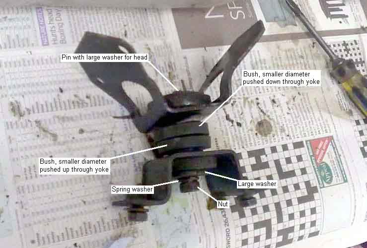
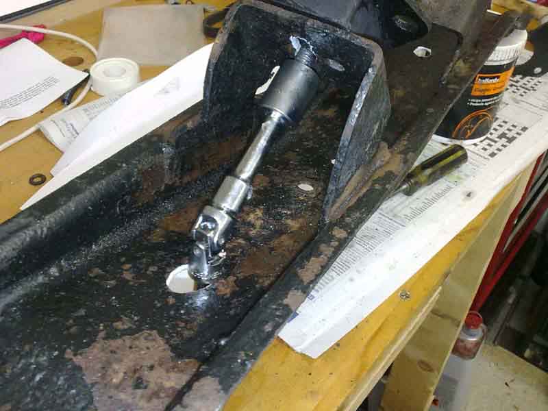
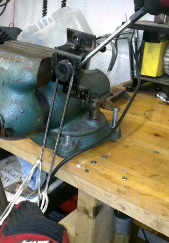
To dismantle the yokes, use a mole grip on the top ōdiscö to allow removal of the nut and washer at the bottom. With so much apart it is pointless not to renew the rubber ōbobbinsö that are a feature of the two yokes. These are a pig! I reduced the diameter of the smaller of the two ōdiscsö from 32mm to 28 mm using a belt sander whilst rotating the bobbin. The technique is to heat the bobbins, and use Vaseline on both it, and the metal yoke. Put the yoke in a vice, and put a loop of nylon cord around the waist of the bobbin (check which way up they go ¢see parts diagram) with the ends passed through the hole in the metal yoke. Pull downwards so the lower edge of the smaller diameter ōdiscö of the bobbin goes through the hole and use a blunt pusher (6mm punch) to push the rest in ¢ working round the disc. Note that it makes sense for the narrower diameter of each bush to be pushed through from the side that doesn't have the lip round the edge of the hole.
I managed to snap two across the middle-perhaps they were faulty......
Clean up the captive nuts in the bottom yoke and the threads on the bolts (or replace) use Coppaslip! John Twist mentions squeezing (or stretching) the lower yoke in a vice so the bolt holes in the cross-member line up with the welded nuts on the yoke. It's a good time to check and adjust this alignment now.
Having re-assembled the 2 yokes with new bobbins I was unimpressed with the amount of ōslopö in the whole arrangement (see here for comments on the various engine/gearbox restraint methods over the years), especially when viewed against the effort of getting the bobbins in. However it allows more ōwiggle roomö during re-assembly.
Now back to the cross member. The new rubber mounts are likely to have far less give in them, so it will be more difficult to lever the cross-member on than removing it-and it has to be in the right place! Elongate the fitting holes to about 15-18mm-upwards. This should allow the cross-member to be lifted and located easily(!) on the protruding studs of first one and then the other mount. Clean the cross-member mounting bolts ¢or replace- and put Coppaslip on these. I also slightly enlarged the holes in the cross-member through which the bolts go to hold the lower yoke, to aid reassembly. Note John Twists's video (and also this very wordy alternative) shows one of these holes elongated so neatly that it seems 'factory', however this cross-member didn't have that.
Note the bolts holding the yokes and rubbers to the gearbox are UNC. Clean the threads. The corresponding drillings in the box casing are probably clean, but worth running a new bolt (or a tap) to check. Again I Coppaslipped the lot!
Generally the fitting holes in the shoulder on the cross-member are front for non-o/d and back for o/d. Mine were front for o/d....The upper yoke always has the flat face pointing forward. The cross-member always has the cut out (for the earliest gear box steady bar) pointing forwards. Check the alignment of the lower yoke captive nuts and the holes in the cross-member. Using longer bolts with a filed point to aid location would be easier than refitting the short original ones, and allows for some wiggle room on re-assembly. Once the assembly was tightened (but before bolting up the cross member) I removed these long bolts one at a time and replaced with short ones. You could leave the long ones in, but the protruding thread will corrode make disassembly more difficult next time!
Re-assembly: Now is a good time for examining faults with either the reversing light switch or the overdrive switch, and for treating the inside of the chassis box sections with Waxoyl or Dinitrol.
Re-assemble the two yokes with the pin through the two bobbins. Mount this and the rubber mounts on to the gear box. The top yoke will be firm, the lower one able to move.
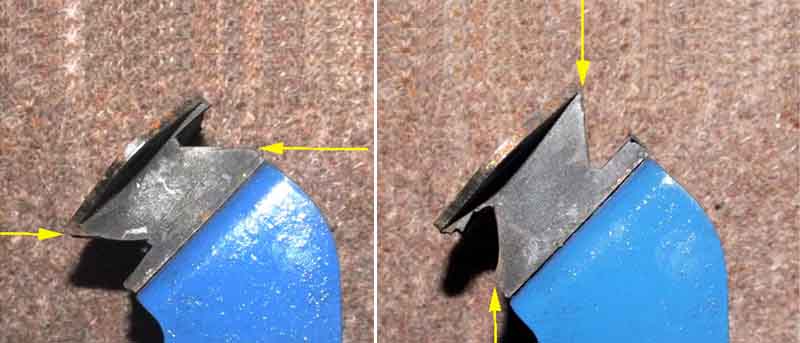
November 2014: If there wasn't already enough options for assembly some suppliers now have the rectangular rubber mounts with cut-outs, meaning that whereas before they could be fitted either way round, now there is a difference in the shape of the rubber and the forces acting upon it, making them 'handed'. In the orientation as shown on the left the unsupported faces are horizontal, but as fitted on the right they are vertical. Logic dictates that vertical is correct, as the main weight of the gearbox acts vertically so the rubber will be in compression. If fitted horizontally the rubber would experience a significant shear load. It's true that when in use the forces could be in any direction, including fore and aft, but as with very few exceptions cars spend more time sitting than running, it seems that fitted as shown on the right is preferable. (Images from Graham Barker)
Wiggle the cross-member roughly into position resting up against the yoke assembly. Use the longer bolts mentioned above to lift the cross-member and take its weight. Starting on the left-hand side, waggle the cross-member on to the stud of the rubber mount. With a little squeezing lift the other side on to its corresponding stud. Tighten the bolts that hold the cross-member to the yokes just enough to prevent the cross-member dropping away-no more.
Jack up the gearbox enough to remove the packing supporting it on the fixed cross member. I left an 18mm thick block, which still allowed access for the next operation.
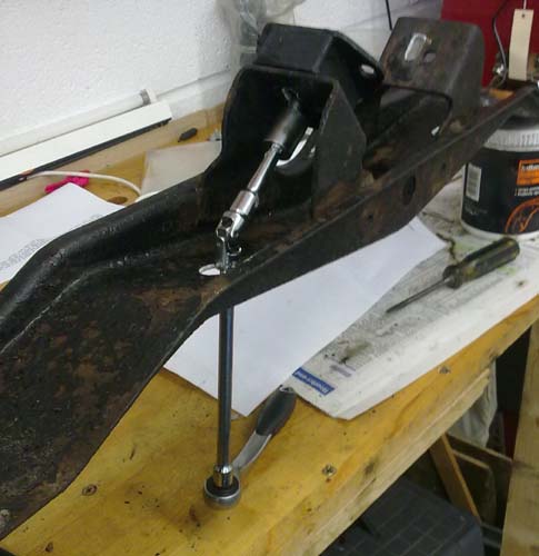
The angle of the studs (protruding through the supports) is downwards, making fitting washers and nuts difficult. Start with the more difficult left-hand side. Coppaslip the stud to assist with stiction. I opted for a single spring washer, and used one of those spring tools with 4 claws (operated by your thumb on a plunger) to hold the washer. There is a convenient slot through which you can offer the washer and gently press it over the stud with a finger on your other hand! Put the nut in the socket, and place the socket above the elongated hole in the cross member. Fit the short extension bar through the cross-member on to the socket and allow to hang (vertically). Fit the U/J and the longer extension bar. Use two fingers to locate the short extension/socket/nut on to the stud, whilst maintaining a little upward pressure on the long extension as you twist it. Repeat for the right-hand side where the long extension is all that is needed. Remember to refit the earthing strap on rubber bumper cars and V8s!
Snug the long bolts through the cross-member into the lower yoke. Remove one and replace with one of the correct length. Tighten this and repeat for the other long bolt. This isn't because the standard bolts don't fit until the bushes have been compressed, but because it is a juggling act holding the cross-member up, keeping the lower yoke at the right angle, and lining up the cross-member hole with the yoke captive nut so you can start the bolt, the longer bolts make this easier.
Jack up the gear box (not the cross-member as you may need to waggle it to fit) until the cross-member is correctly located, and refit the 4 bolts.
© Copyright Michael Beswick 2011