Non-positive system used until February 1964. This uses a hose from the rocker cover to the front air-cleaner (outside the filter) and a non-ventilated oil filler cap: (Clausager Original MGB)

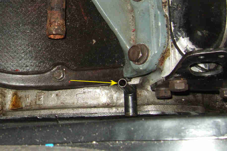
There is also a hose on the front tappet chest cover clipped to a stud or blanking-plate screw where the mechanical fuel pump is on other models, just hanging down with an open end: (Auto-Part.com)
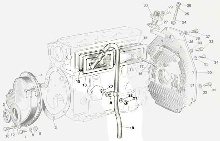
The result was pretty ineffectual, with the air-cleaner hose being outside the filter it was basically at atmospheric pressure, relying on resistance to air being drawn into the cleaner to create any kind of suction. If and when suction did occur crankcase fumes had to pass through the filter making it dirty on the way to being burnt in the engine. By the same token any such suction would pull air from below the engine into the crankcase hose - complete with any dirt or moisture. It was equally possible that the crankcase hose - also known as a road draught tube, could experience suction from forward motion which would emit fumes direct to the atmosphere, and draw air via the rocker cover tube from the 'dirty' side of the air-cleaner i.e. unfiltered. So pretty poor whichever way air flowed.
In February 1964 a Positive Crankcase Ventilation system was implemented. Until October 1968 it consisted of a PCV valve (13H5191) mounted on the inlet manifold, plumbed to a port on the front tappet chest cover. The oil filler cap is now ventilated with a restriction and a filter: (Clausager Original MGB)
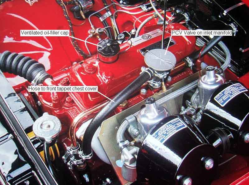
A much better system that used inlet manifold vacuum to draw air from the crankcase, letting filtered air in through the rocker cover. The PCV valve restricted how much suction that could be applied to the crankcase to limit how much oil as droplets could be pulled though, the tappet chest cover containing an oil and flame trap mesh to further reduce droplet flow. The rocker cover cap as well as being filtered also had a restriction to reduce air flow still further. This resulted in a small standing negative pressure inside the engine while it was running which helped reduce oil losses through seals. However with a flexible diaphragm, spring and needle valve they do eventually wear out which can cause excessive suction and oil burning.
Order of assembly - the spring goes in the casting first, then the plunger sits on the spring with the pin pointing towards the hole at the bottom of the casting (not the one on the side). The diaphragm sits on top of the plunger, with the plunger disc sitting in a large recess in the diaphragm. Difficult to show profile detail of a photo of the black rubber diaphragm hence the simple line drawing below. The cap fits on top of the diaphragm with the ribs facing down and the recesses facing up (any 'writing' should be legible with the cap fitted but some are plain). The cap has a breather hole (lower right here) which allows air in and out above the diaphragm as manifold vacuum pulls the diaphragm down or the spring pushes it back up. The ribs facing down allows air to flow freely across the whole of the top of the diaphragm. Note that this air does not pass through or past the diaphragm into the body of the valve, unless the diaphragm (or possibly casting) is faulty in which case the faulty component(s) should be replaced as it will result in excessive suction on the crankcase and probable oil burning: (image components from various sources)

Finally a spring clip presses the cap down onto the diaphragm. Manufacturer/patent info legible here but replacements may be plain:

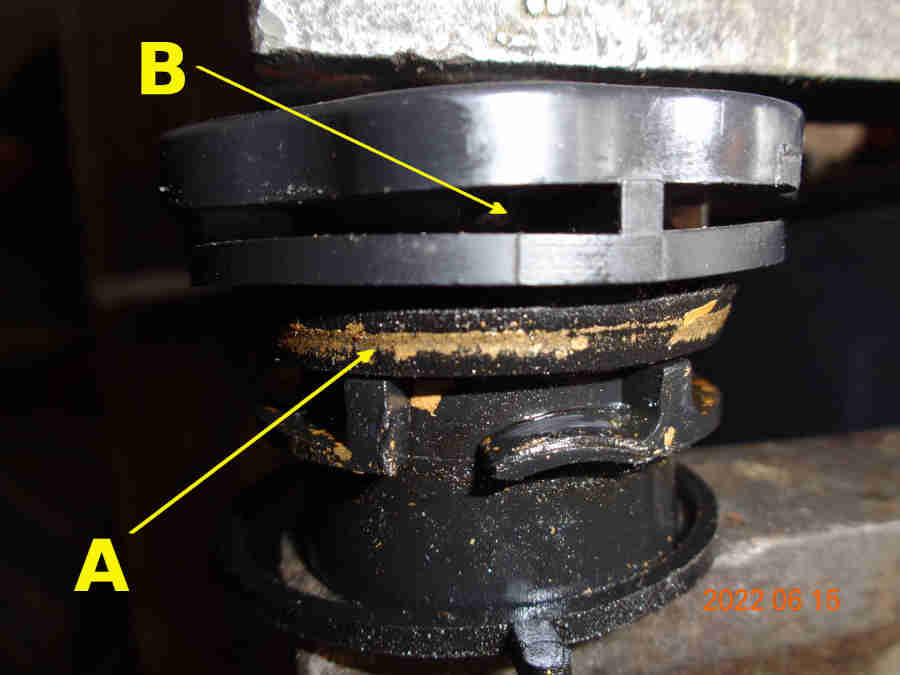
Ventilated oil filler cap, with filter gauze visible through the hole at the bottom, used on non-North American spec MGBs until the end of production:
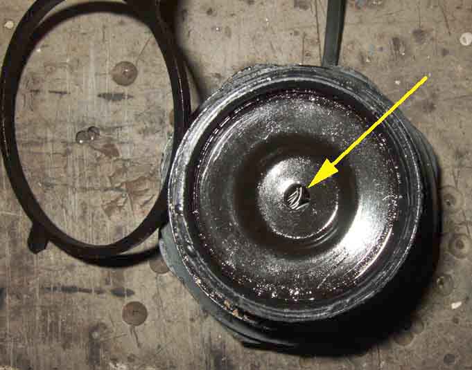
'A' is the rubber seal to the filler neck, 'B' is one of two air inlet holes:
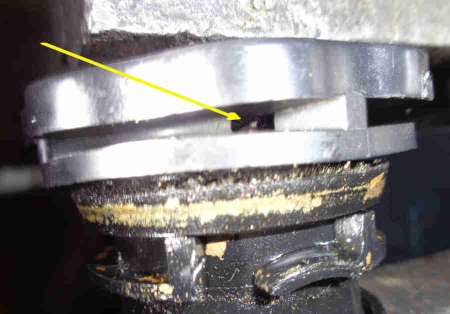
One of the two air inlet holes, just above where the cap locks onto the pins in the filler neck. With a light shining straight down onto the hole you can see the filter mesh:
Non-ventilated caps of this type i.e. plastic have no path through and no filtering gauze inside, and are only used with North American PCV systems that include the charcoal canister.
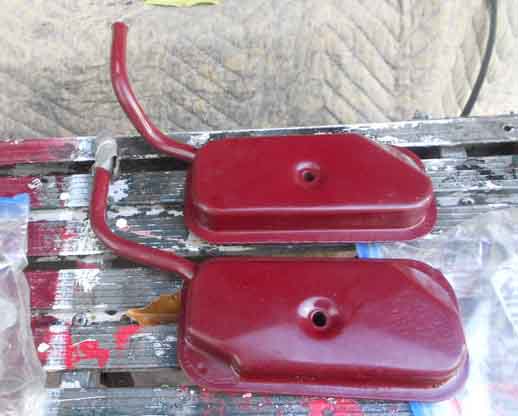
Front tappet chest cover 12H1399 (at the top here) with internal filtering and oil separation, used with the PCV valve: (Chris Howells)
In October 1968 the PCV valve was replaced by carb ventilation, with ports on both carbs connected together and taken down to the front tappet chest cover. The oil filler cap is ventilated as before. This system was used on RHD cars until the end of production:
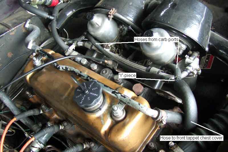
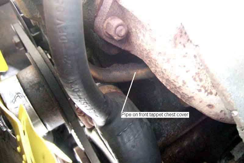
This utilises a feature of the SU (and Zenith/Stromberg) carbs where between the throttle butterfly and the needle piston there is a relatively constant low-level suction all the time the engine is running (this is why such carbs are known as 'Constant Depression' carbs) regardless of throttle opening as the vacuum source. No additional moving parts or components so trouble-free unless excessive oil or blow-by from a worn engine clogs things up, which is equally possible with the earlier PCV valve system.
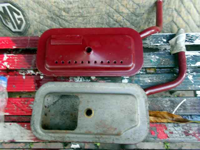
Cover with external filter and separator 12H3684 used with carburettor ventilation until the 18V779/780 engines during the 74 model year: (William Revit in Tasmania via the MG Enthusiasts forum.)
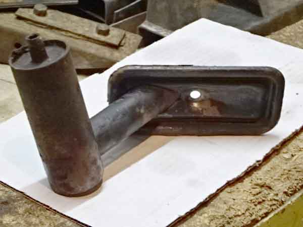
Cover 12H4395 (at the bottom here and very similar to the earlier 12H1399) again with internal filtering and oil separation, used with original 18V797 and later engines. However the Parts Catalogue states that rebuilt engines 18GG and later also used this cover (as is the case with Bee's Gold Seal): (Chris Howells)
Note the small difference at the external lower left corners between the two covers, but they are very different internally: (Chris Howells)
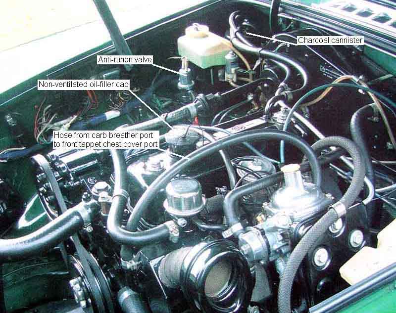
North American spec from October 1969 with the charcoal canister. Originally with twin SUs connected to the front tappet chest cover as before, but with a non-vented oil-filler cap as fresh air was drawn from the canister. This version shows the later single Zenith/Stromberg carb and anti-runon valve: (Clausager Original MGB)
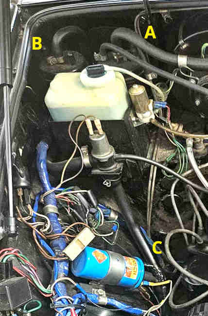
1978 models gained a second canister is tandem with the first as in this 1980 model. 'A' is the primary and 'B' the secondary. When first reading about this I had assumed (I know, I know) the second canister would be on the fresh-air side of the anti-run-on valve as that has a hose from the inlet manifold, with the potential for fumes to escape to atmosphere. But 'C' clearly shows the fresh-air inlet is still the valve and not the secondary canister: (Bill Etter)
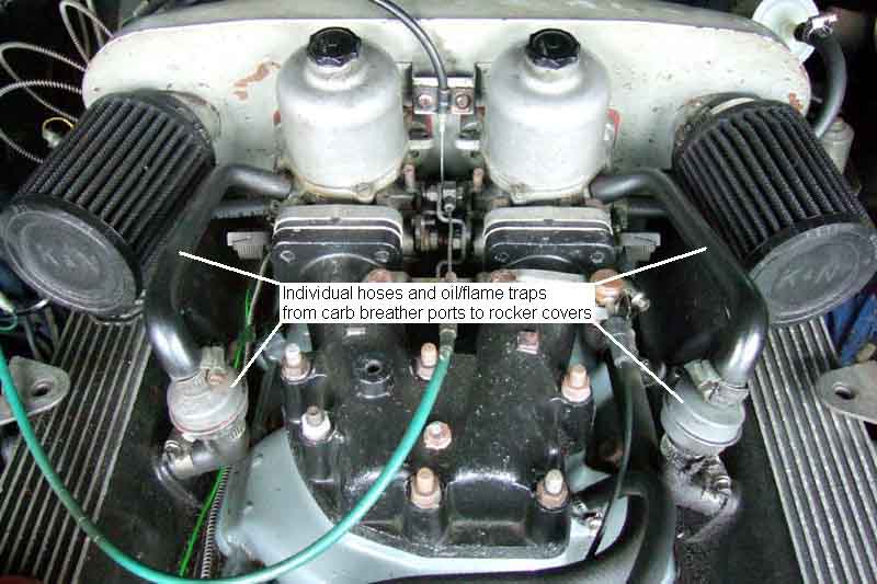
V8 with individual hoses and oil/flame traps from carbs to rocker covers:
Rear of the V8 air-cleaner box showing the breather intake filter with mounting clip and hoses, the oil filler cap in unventilated:
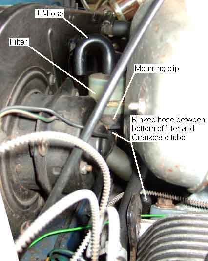
Clutter out of the way, the vent is a horizontal tube with a closed outer end pushed into the back of the block with a vertical tube pointing up to take the short hose to the filter: