
North America with Ignition Relay (1977-80)
")
Note 1: There are two browns from the alternator to the solenoid, some schematics showing them as two thick output wires i.e. using a '' alternator, and some showing one of them being standard gauge i.e. using a '' alternator.
Note 2: Some schematics show two thick browns up from the solenoid to a white connector block by the fusebox (shown below, arrowed), to increase current carrying capacity. The way this is drawn in some factory diagrams indicates that the two browns are separated in this connector, unlike a 4-way bullet connector, and probably incorrect as others show the two brown circuits as linked in the connector which makes more sense. One output feeds the fusebox and ignition relay, the other feeding the lighting and ignition switches. A third brown from the solenoid feeds the starter relay and hazard flasher fuse.

There are differences in the main power wiring between the Leyland and Autowire drawings for late models as follows:
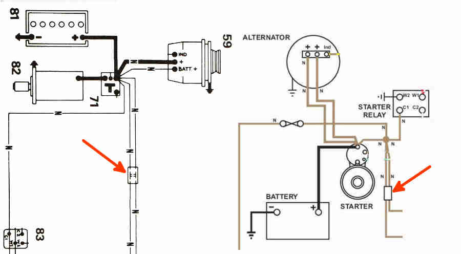
- There are five brown wires at the starter solenoid on Leyland but only three on Autowire (plus the battery cable on both).
- Both show two going to the alternator but Leyland indicate one of these is a standard gauge to the Batt+ terminal (battery sensing system) however this was not used after 1976, instead the two terminals were both output terminals with thicker wires as per Autowire.
- Autowire shows the third solenoid wire going to a sealed connection and from there to hazard fuse and starter relay plus two more to something that looks like a 4-way bullet connector and from there to the remaining components.
- Leyland show a wire from the solenoid to the starter relay and hazard fuse, then two more from the solenoid to a connector that on the face of it also looks like a standard 4-way bullet connector with one brown wire from it feeding the lighting switch and ignition switch and another feeding the fusebox and ignition relay. However the drawing shows two lines inside this connector joining the two through-connections indicating all four wires are connected together (i.e. it is not a 2-pin plug and socket as used for cooling fans) instead of only one on standard 4-way bullet connectors. A subtle difference, but the component concerned is completely different being the white plastic component above rather than a standard black 4-way bullet connector.
- Leyland show a similar arrangement for RHD as for North America but without the white plastic connector, however a harness removed from a UK 1980 model did have a sealed connection with four wires!