
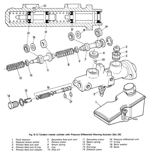
General principle of a dual-circuit master cylinder: (How Stuff Works)

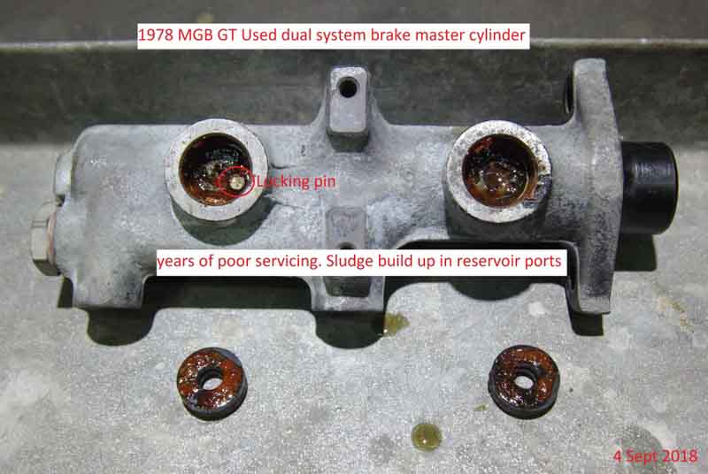
Note the ports from the right-hand reservoir (primary) are incorrect, the one with the red arrow should be to the right of the seal on the piston to allow the space at the back of the pressure seal to fill, as with the left-hand reservoir.
Initially both pistons move - the primary from the push-rod and the secondary from the primary via the spring, but the secondary moves at half the rate of the primary as that has a second spring in front of it and both are being compressed. If the primary circuit starts developing pressure first its spring is not compressed any further, instead fluid pressure pushes the secondary piston at the same speed as the primary until that develops pressure. If the secondary circuit develops pressure first that piston stops moving and the primary piston continues until that circuit develops pressure. In practice with calipers on the primary circuit and drum brakes on the secondary the primary circuit is likely to develop pressure first.
If there is a leak in one of the circuits that circuit will not be able to develop pressure. When the primary circuit leaks the primary piston contacts the secondary cylinder to maintain pressure in that circuit, however with the loss of front caliper braking there will only be about 30% braking effectiveness available from the rear drum brakes (try stopping with just your handbrake!). If the secondary circuit fails that piston will move to the end of the cylinder and stop, only then does the primary circuit start to develop pressure. This will result in more pedal movement than normal, again less braking effectiveness but not as much loss because the front brakes i.e. the primary circuit deliver 60-70% of the total braking effort.
1968 to 74 North American unboosted dual master 37H2780, two outputs to a separate manifold unit that contains the pressure failure switch:
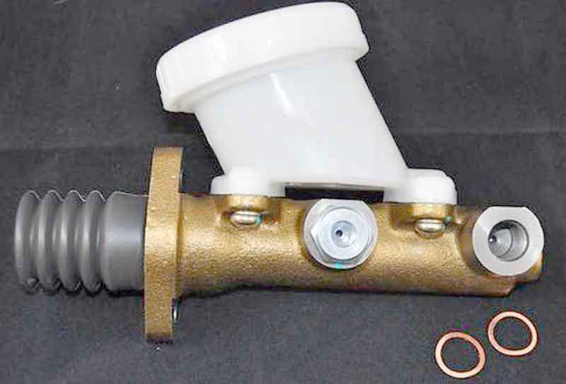
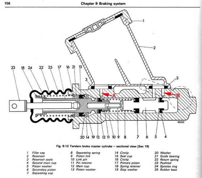
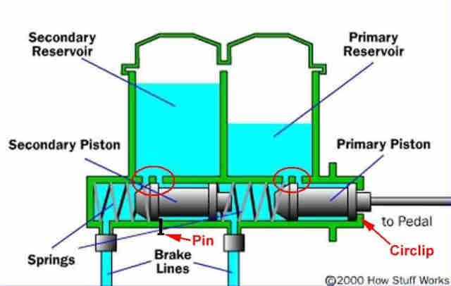
Internals from Haynes:
The remote pressure failure switch assembly 13H5905: (Somerford Mini)

Internals from Moss Motors:
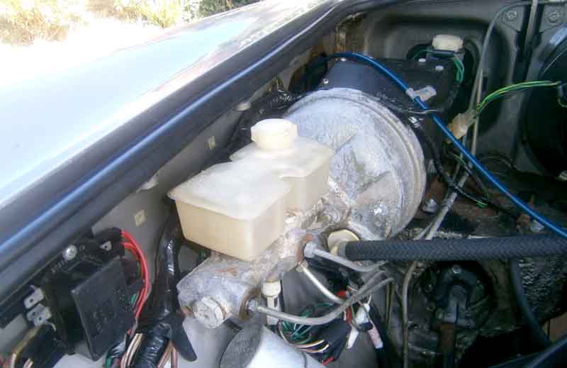
1974-on North America and 1977-on RHD dual brake master with integral servo:
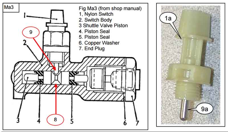
Next three images from John Maguire in Australia:
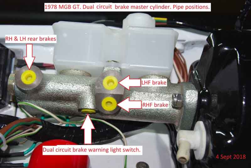
It's important to note that the hydraulic ports have a metric thread whereas the balance switch port, and the rest of the unions in the brake system are Imperial, as described by John Twist in his excellent rebuild video). There can be two sizes of O-ring for the shuttle valve and two types of seal for the reservoir mounting, not all rebuild kits contain all parts.
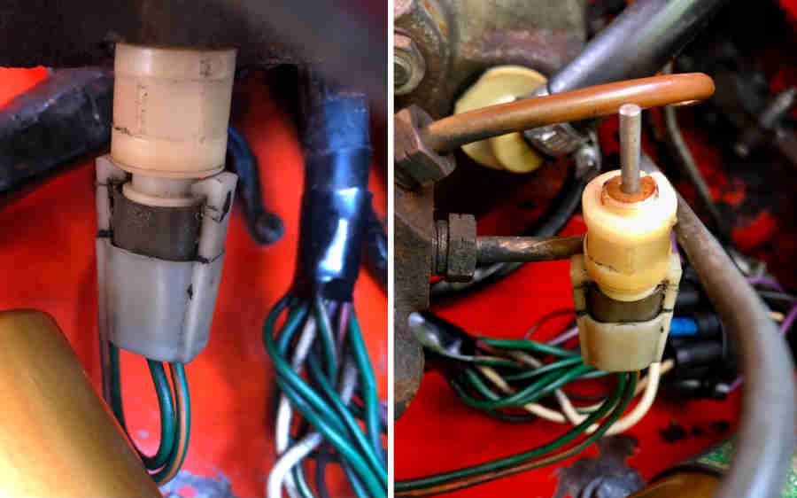
Care is needed with the switch (AAU2454). It's only plastic and screwed into a casting it can seize, snapping off if too much force is used as here: (anon)
Drawing from Haynes. Note the reservoir on the MGB can be rectangular or wedge-shaped. In the images above John has removed the plug and spacer for the differential switch unit from the master but not the differential unit (shuttle) itself. The two O-rings 17 are probably what fails and causes fluid to leak from the switch. The BL Parts Catalogue shows repair kit 18G9081 which only came up with a couple of sources in the US (which didn't look like they had these O-rings) and an Amazon page (unavailable). According to John Twist in the above video there can be two sizes of O-ring for the shuttle valve and two types of seal for the reservoir mounting, and not all rebuild kits contain all parts. But the Amazon page listed several equivalent part numbers and Googling those one took me to Brown & Gammons GRK1004. This has several more components than the US sites including some small O-rings which hopefully will be for the shuttle, and also contains the outer seal, washer and housing that John Twist says is not included:
One (unverified) opinion has it that with a circuit failure on this later system the shuttle valve moves to light the warning lamp and latches in that position, but also blocks off the leaking circuit.
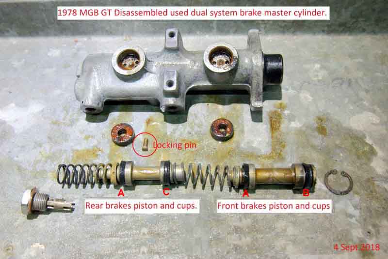
Primary reservoir ports corrected. Showing the position of the locking pin which this is necessary to position the secondary piston in exactly the right place between the two ports with the pedal released. Also the push-rod end of the cylinder retains the internals with a circlip or you wouldn't be able to get them in!:
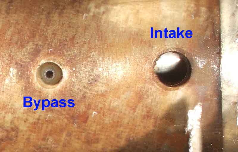
Although Haynes shows different arrangements for the front and rear passages from the reservoir to the main casting John Maguire just shows two identical seals and that's all John Birbeck found. John B had fitted a new master cylinder but couldn't get any fluid to flow from the reservoir to the front brakes. There is a passage from the shuttle valve to the front ports, but not down from the reservoir! John M shows two small holes in the casting under the reservoir which are probably the inlet and bypass ports for in front of and behind the pressure seal, perhaps the inlet in John Bs is blocked. In the single circuit master this is a very small passage, which looks like it has been drilled then a bead with a tiny hole pressed in closing most of it off:
Servo:
The push-rod from the servo acts directly on the master cylinder piston:
