
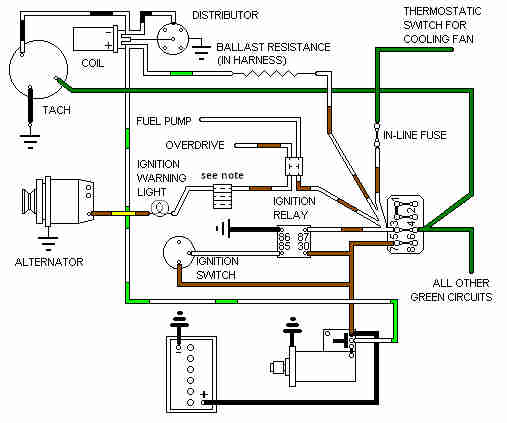
Note: This is one of three multi-way plugs behind the dash.
August 2026: If the ignition relay fails no ignition-powered circuits will work. The engine will start when you turn the key to crank but cut out again as soon as you release it, this is because the coil has an alternative power supply during cranking from the starter solenoid.
When there are there or more wires on the input side of the fusebox (as with the four white/brown wires here) only one of them is supplying 12v, the other three are daisy-chaining it on to other circuits. There is only ever a maximum of two wires in a factory spade connector, that means that whichever wire is sharing the spade connector with the 12v supply wire it will still have its 12v supply even if the spade connector is removed from the fusebox. The other wires of that colour e.g. two white/browns will be in their own shared spade connector which is fitted to the partner spade on the fusebox. As a result if the 12v supply spade is removed from the fuse box these other two wires will lose their supply, as well as the circuits fed by that fuse. The same thing can happen if there are bad connections between the two spades on the back of the fusebox, or the spades or connectors are themselves corroded.
There are two separate green circuits - the original circuit fed from the 2nd fuse up in the 4-way block for all the original green circuits, and another fed by an in-line fuse from the white/brown circuit on the relay output for the cooling fan. This fuse is located below the fusebox, probably with the hazard flasher fuse which has brown wires both sides.
There are three separate white circuits - one from the ignition switch feeding the ignition relay, another in the rear harness feeding the fuel pump, and the third in the dashboard sub-harness feeding the ignition warning light. These last two are taken off the white/brown circuit from the relay output.
The schematics show the original rectangular Lucas relays with W1, W2, C1 and C2 terminal numbering, but in practice cylindrical relays with ISO numbering were fitted. The relationship is as follows:
| Wire colour | Original numbering | ISO numbering |
| White from ignition switch | W1 | 85 |
| Black earth | W2 | 86 |
| Brown 12v supply | C2 | 30 |
| White/brown to ignition powered circuits | C1 | 87 |
Information on the ballast resistance can be found here.