
The 'electronics' is easy, at the simplest level it need not be anything more complicated than a buzzer, with a switch that closes when the fluid level drops. An enhancement is if the buzzer is made to sound by the switch opening when the fluid level drops, which also monitors the wiring between the buzzer and the switch. A further enhancement is if the buzzer can be made to buzz briefly each time you turn on the ignition, to let you know that the buzzer itself is working OK and the wiring to the switch is complete.
The tricky bit is the switch. BL cars in the 80s had a master cap that contained a float and a switch, which are probably still available if you look around, but the masters and even the caps are much bigger then the MGB items, and would not fit in the same space even if everything else about them was 'correct'. So I started experimenting, and knowing that water conducts electricity, I wondered if brake fluid did, and it does! Old fluid did, but that could already have absorbed water, but new fluid did as well. However that was glycol fluid, I didn't know if silicone (which I don't have anyway) would be the same. But more importantly I wasn't happy about passing a current through brake fluid, no matter how small with the appropriate electronics, as voltages and currents where metals and fluids are brought together can cause corrosion. I looked at capacitive fluid detection, some of which can be external to the reservoir, but it would have to be a plastic reservoir, it doesn't work with metal as both mine are. Replacement masters come with plastic reservoirs from the usual suspects and are the only type available (although the same applied to clutches until recently, now metal reservoirs are available again, perhaps OE-style brake masters will be too). You can also do capacitive detection with something dipping in to the fluid, but the circuitry required for that is quite complex. That left floats, as used by BL earlier.
I have plastic caps which very conveniently have a flattish top that clips into the main part of the cap:
This gives a convoluted air path, for air to move in and out of the reservoir as the fluid expands when heated through driving, and cools again when parked. It's essential that air pressure can escape, or it will increasingly apply pressure to the fluid which will apply the calipers at least, generating more heat, more expansion, and more pressure on the brakes. The down side of this air going through the cap is that it can suck moist air in, which will be absorbed by glycol fluid. Silicone fluid is no real solution - it won't absorb the moisture, but the same amount of moisture will be in there, and it condenses into droplets and lies around inside the system. But I digress. Because the top flips off there is the possibility of mounting something inside the cap, or attached to the lower main part and projecting down inside the master.
I considered various types of hollow container that might go through the filler hole, and cork. Attaching the tube but allowing it to move up and down was a non-starter as being too fiddly, but the cork was a possibility as a hole could be drilled through the middle for it to float up and down on a spindle attached to the cap. I wondered whether the cork would soak up fluid and become too heavy, so left one floating in a small container of fluid for some weeks, and it didn't seem to be sinking over time. However once I had fitted a spindle through it, it tended to stick to the spindle and not go up and down freely. Vibration from driving may well be enough to jiggle it down if you were losing fluid, but I wasn't that happy with it.
But that's only part of the requirement - the other is some kind of switch to be operated by the float. Mechanical operation just seemed too iffy, the contacts would have to be very light to be moved by a float in brake fluid, and really would need to be sealed from the atmosphere to prevent contamination and bad connections. Reed contacts are the obvious choice as the contacts are sealed in a glass tube containing an inert gas, and are operated by bringing a magnet into close proximity.
 I had some rectangular surface-mount burglar
alarm door switches which contain just such a reed contact in the part that
attaches to the frame, and a magnet in the part that screws to the door. But
two problems - the reed contact was very flimsy and as soon as I tried to do
anything with the wires coming out of the ends of the glass tube the ends would
break away and the two halves would fall apart. The magnets were also too large
to sit on a float.
I had some rectangular surface-mount burglar
alarm door switches which contain just such a reed contact in the part that
attaches to the frame, and a magnet in the part that screws to the door. But
two problems - the reed contact was very flimsy and as soon as I tried to do
anything with the wires coming out of the ends of the glass tube the ends would
break away and the two halves would fall apart. The magnets were also too large
to sit on a float.
But
researching magnets I came across very small ring magnets, which were worth a
punt. However with the reed contact lying across the underside of the cap, the
magnet rings had to be on their sides to operate the contact, which meant I
couldn't have a hole up the middle and a spindle. I tried them inside a copper
guide tube attached to the cap, but it stuck even more, and I didn't like the
idea of copper parts in the fluid.
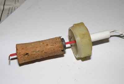 A pal was also experimenting and he had a
different type of flush-mounted door contact that can be fitted in the upper
part of the cap. This has the reed contact orientated differently, so that the
ring magnets can lie flat on the top of the cork, with a thin spindle passing
through them and the cork acting as a guide and a retainer. However the cork
tended to stick to the spindle as well.
A pal was also experimenting and he had a
different type of flush-mounted door contact that can be fitted in the upper
part of the cap. This has the reed contact orientated differently, so that the
ring magnets can lie flat on the top of the cork, with a thin spindle passing
through them and the cork acting as a guide and a retainer. However the cork
tended to stick to the spindle as well.
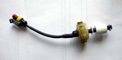
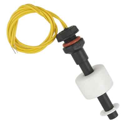 More research into float switches came up with
a commercial product that looked to solve both problems. These have a
polypropylene foam float containing a ring magnet, that slides on a spindle
that contains a reed contact. Furthermore by turning the float over, you can
arrange for the contact to close when the float drops, or to open when the
float drops - this latter being just what I wanted. If that wasn't enough they
have a thread, sealing ring and plastic nut at the top end where the wires come
out which will be ideal for securing it to the master cap. There were various
offerings from a couple of suppliers, with different dimensions, the most
important being the float diameter, as it has to fit through the filler neck.
Float diameters were either 15mm or 19mm, and checking my masters they varied
between 17 and 19mm. The length is also a factor, there is 56mm available from
the top of the neck to the metal plate over the cylinder inside the reservoir.
But for the items on sale only overall lengths were given at 72mm and 44mm
respectively. And although the overall length included the mounting flange and
thread, I couldn't be sure if the longer one (which had the narrower float)
would fit. So I ordered the shorter one, very cheap and free P&P even
though it comes from China, but it does mean a wait for them.
More research into float switches came up with
a commercial product that looked to solve both problems. These have a
polypropylene foam float containing a ring magnet, that slides on a spindle
that contains a reed contact. Furthermore by turning the float over, you can
arrange for the contact to close when the float drops, or to open when the
float drops - this latter being just what I wanted. If that wasn't enough they
have a thread, sealing ring and plastic nut at the top end where the wires come
out which will be ideal for securing it to the master cap. There were various
offerings from a couple of suppliers, with different dimensions, the most
important being the float diameter, as it has to fit through the filler neck.
Float diameters were either 15mm or 19mm, and checking my masters they varied
between 17 and 19mm. The length is also a factor, there is 56mm available from
the top of the neck to the metal plate over the cylinder inside the reservoir.
But for the items on sale only overall lengths were given at 72mm and 44mm
respectively. And although the overall length included the mounting flange and
thread, I couldn't be sure if the longer one (which had the narrower float)
would fit. So I ordered the shorter one, very cheap and free P&P even
though it comes from China, but it does mean a wait for them.
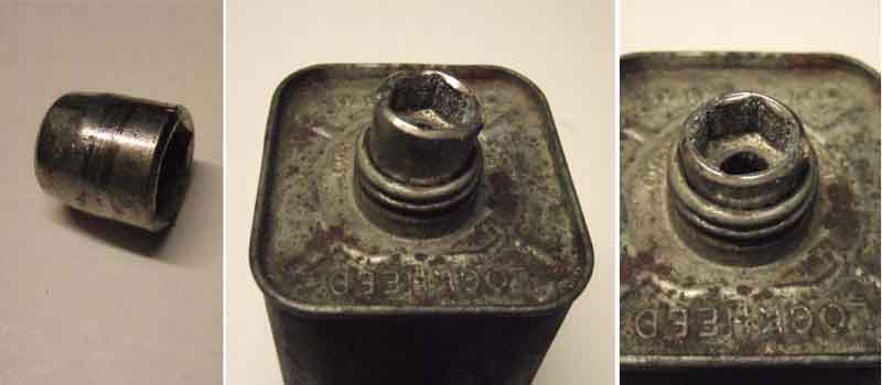
When it arrived I found the float would not fit through the neck. The neck size can be pretty variable, as although the OD is fairly precise as you have to be able to screw the cap on and tighten it down i.e. it can't be too big or too small, but at the top of the neck it is turned over and back down inside itself so it doesn't leave a sharp edge, and the ID can vary by quite a bit. I had two options - try and turn down the float a bit, or expand the neck. The float was first, I put it on an arbor and spun it on a drill, and used glass-paper gently on the surface. It did very gradually reduce the diameter, but of course left tiny flakes hanging on that I didn't want dropping down inside the master, and it was on the verge of melting even with light pressure. That left modifying the master.
By experimenting on an old master that had rusted through (I knew it
would come in handy one day ...), and with an old nut driver I had found years
ago in my father-in-laws 'bits drawer' I found that it was relatively easy to
carefully press the turned over edge outwards, making the hole bigger, without
distorting the thread on the neck. A large pair of pliers can do the same job,
as long as it has rounded faces to the outer edges of the jaws so fragments of
metal are not scraped off the opening.
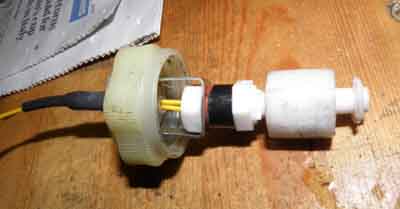
I've got two choices - I can either fit the threaded part of the spindle up through the main part of the cap and have the nut under the top cap, or I can fit the spindle down through the main part of the cap, and have the threaded part going through the top cap and the nut above that. Unfortunately not so easy, having set the float correctly so that it opens the reed contact when fluid level falls, I find that not even the lower position i.e. with the nut inside the two halves of the cap, does the float rise high enough to close the contact.
 I pondered spacers and brackets to position
this short switch lower down, and a pal did opt for that method. However it
does mean that as you unscrew the cap the switch and the wiring from it twists
as well.
I pondered spacers and brackets to position
this short switch lower down, and a pal did opt for that method. However it
does mean that as you unscrew the cap the switch and the wiring from it twists
as well.
 I decided to go for the longer switch, but that
has its own issues. The float rises far enough to close the switch, but even in
the higher of the two mounting positions the bottom of the switch spindle hits
the internal plate over the cylinder before the cap is fully screwed down. The
float is retained on the spindle by a plastic circlip in a groove, and there is
about 1/4" of spindle below that, giving me some scope to shorten it. This
I do, and now it fits, but has exposed the end of the reed contact connection
wire! Not ideal, as it puts an electrical circuit in contact with the fluid
which I was tying to avoid. But as one side of the switch will always be at
earth, and the metal can of the master is always at earth potential, as long as
I connect the earth to the exposed side of the switch there shouldn't be a
problem. Also because the flange on the switch is between the upper and lower
halves of the cap I don't need to fit the nut which means the float switch can
swivel, and hence its wiring can stay still while I'm turning the cap to remove
or refit. But there is another issue with the float this way round, and that is
if the float rises high enough up the spindle, the reed contact opens again. It
may never rise that far in practice, but to be sure I cut a groove round the
spindle and fit another circlip above the float, limiting its upwards movement
to below that at which the reed contact opens. After that it was a relatively
simple matter to strengthen the thin wires by replacing most of the length with
stouter wires, covering them with layers of heat-shrink including over the
thread at the top of the switch, and connecting them to a 2-pin plug (of which
more later).
I decided to go for the longer switch, but that
has its own issues. The float rises far enough to close the switch, but even in
the higher of the two mounting positions the bottom of the switch spindle hits
the internal plate over the cylinder before the cap is fully screwed down. The
float is retained on the spindle by a plastic circlip in a groove, and there is
about 1/4" of spindle below that, giving me some scope to shorten it. This
I do, and now it fits, but has exposed the end of the reed contact connection
wire! Not ideal, as it puts an electrical circuit in contact with the fluid
which I was tying to avoid. But as one side of the switch will always be at
earth, and the metal can of the master is always at earth potential, as long as
I connect the earth to the exposed side of the switch there shouldn't be a
problem. Also because the flange on the switch is between the upper and lower
halves of the cap I don't need to fit the nut which means the float switch can
swivel, and hence its wiring can stay still while I'm turning the cap to remove
or refit. But there is another issue with the float this way round, and that is
if the float rises high enough up the spindle, the reed contact opens again. It
may never rise that far in practice, but to be sure I cut a groove round the
spindle and fit another circlip above the float, limiting its upwards movement
to below that at which the reed contact opens. After that it was a relatively
simple matter to strengthen the thin wires by replacing most of the length with
stouter wires, covering them with layers of heat-shrink including over the
thread at the top of the switch, and connecting them to a 2-pin plug (of which
more later).
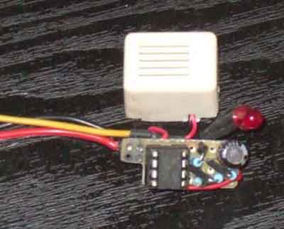
Next the electronics. I wanted the full 'self-check'
version, with LED and buzzer, and as most of my electronics experience has been
with discrete transistors started off with that. I also wanted it to be as
small as possible, and found a Hammond ABS enclosure just 35mm square and 20mm
deep. At the time I had a Maplins 12v buzzer which with a little trimming did
just fit into the case, but only left enough space for a bit of 4 x 11
stripboard, but a 4 x 4 section had to be cut off the corner of that to fit
round the column for the lid screw! I needed two transistors - one as the
detector and timing circuit to give the self-check buzz, and the other to
switch the LED and buzzer on and off. It worked, but after its self-check
period gave an annoying dying squawk as it switched off, as without additional circuitry
the transistors only switch on and off gradually.
 So I tried another version using a voltage
comparator IC and managed to squeeze that into the same space as well. It has a
fixed potential divider to deliver a reference voltage on one input, and a
variable potential divider on the other. The 'variable' part consists of a
fixed resistor on one arm and the float switch being open or closed on the
other, to deliver the variation in the signal voltage. With the switch closed
the signal voltage is lower than the reference voltage which turns the IC off
and silences the warning. With the switch open the signal voltage goes higher
than the reference voltage to turn on the IC and give the warning. A capacitor
across the fixed resistor on the signal input initially pulls the signal
voltage high to switch the IC on and sound the warning - the self-check - but
over a short period of between half a second and a second the signal voltage
falls to its normal level - as long as the level switch is closed - to turn the
warning off again. With positive feedback from the output to the reference
input the IC switches on and off very rapidly - no dying sound.
So I tried another version using a voltage
comparator IC and managed to squeeze that into the same space as well. It has a
fixed potential divider to deliver a reference voltage on one input, and a
variable potential divider on the other. The 'variable' part consists of a
fixed resistor on one arm and the float switch being open or closed on the
other, to deliver the variation in the signal voltage. With the switch closed
the signal voltage is lower than the reference voltage which turns the IC off
and silences the warning. With the switch open the signal voltage goes higher
than the reference voltage to turn on the IC and give the warning. A capacitor
across the fixed resistor on the signal input initially pulls the signal
voltage high to switch the IC on and sound the warning - the self-check - but
over a short period of between half a second and a second the signal voltage
falls to its normal level - as long as the level switch is closed - to turn the
warning off again. With positive feedback from the output to the reference
input the IC switches on and off very rapidly - no dying sound.
 It worked, but I still didn't like the buzzer,
and LEDs coloured red when they are off are not very easy to see in direct
sunlight when they are on. I found an electronic sounder on eBay which is much
smaller than the buzzer and allows me a lot more space for electronic
components. I also selected a different LED - a very much brighter, narrow
angle water-clear type which is very easy to see come on even in direct
sunlight. That all worked fine on the bench, but when connected to the roadster
I found that turning anything on caused the alarm to sound briefly, and when
cranking it was squawking like hen with a fox in the coop. That is almost
certainly caused by the large spikes generated when any conventional electric
component like incandescent lights, motors etc. is turned on and off. So I add
a large electrolytic capacitor across the 12v supply leads, which stops
everything but the cranking interference. That is annoying, but my ignition
switch has the accessories contact that disconnects during cranking, so
powering the electronics from here solves that problem. But only eventually,
because when I first connected it to the accessories circuit it did exactly the
same thing as on the ignition supply. Investigating the wiring of the ignition
switch revealed that two wires were swapped over, so the white that fed the
overdrive was on the accessories circuit, and the accessories wire was on the
ignition! I'd never dug into those wires, so it must have been like it for
years, maybe from the factory. With that corrected the only minor drawback is
that as I turn the ignition key the circuit is powered up from the accessories
and ignition circuits, is disconnected while cranking, then powered up again as
I release the key, so sometimes I get two self-check beeps. But that's a minor
inconvenience. It's installed on the side of the centre console, at the top,
with double-sided sticky tape, angled such that the LED is pointing straight at
me.
It worked, but I still didn't like the buzzer,
and LEDs coloured red when they are off are not very easy to see in direct
sunlight when they are on. I found an electronic sounder on eBay which is much
smaller than the buzzer and allows me a lot more space for electronic
components. I also selected a different LED - a very much brighter, narrow
angle water-clear type which is very easy to see come on even in direct
sunlight. That all worked fine on the bench, but when connected to the roadster
I found that turning anything on caused the alarm to sound briefly, and when
cranking it was squawking like hen with a fox in the coop. That is almost
certainly caused by the large spikes generated when any conventional electric
component like incandescent lights, motors etc. is turned on and off. So I add
a large electrolytic capacitor across the 12v supply leads, which stops
everything but the cranking interference. That is annoying, but my ignition
switch has the accessories contact that disconnects during cranking, so
powering the electronics from here solves that problem. But only eventually,
because when I first connected it to the accessories circuit it did exactly the
same thing as on the ignition supply. Investigating the wiring of the ignition
switch revealed that two wires were swapped over, so the white that fed the
overdrive was on the accessories circuit, and the accessories wire was on the
ignition! I'd never dug into those wires, so it must have been like it for
years, maybe from the factory. With that corrected the only minor drawback is
that as I turn the ignition key the circuit is powered up from the accessories
and ignition circuits, is disconnected while cranking, then powered up again as
I release the key, so sometimes I get two self-check beeps. But that's a minor
inconvenience. It's installed on the side of the centre console, at the top,
with double-sided sticky tape, angled such that the LED is pointing straight at
me.
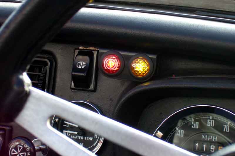
At one point I bought a couple of after-market warning lights - one with a brake symbol and one with an oil can for an oil pressure warning light. However they weren't very bright, certainly no good for the roadster with the top down and the sun shining, so didn't use them. But eventually I worked out how to prise the lenses out without damage. Underneath is a standard red LED (behind an red lens, orange behind orange for the oil) with dropper resistor to operate off 12v. These old-style coloured LEDs are not very bright at all, and the lens reduces it still further. Interestingly the led/resistor legs had two fine springs pushed onto them, and they fitted onto two spikes which came up from the external terminals of the light unit, making removal and refitting very simple - no soldering. So it was a simple matter to take a super-bright white LED and fit that instead without a resistor, which is inside the electronics module. With the corner of a bit of square, black plastic drain down-pipe I fabricated a mini-panel to hold both, which simply pushes into the gap between the dash and the crash-pad. Much brighter than before, it's only in full direct low-level winter sun that the light becomes less easy to see. Not a problem as that has an audible warning as well.
After-market warning lights modified with superbright LEDs: Visible from the driving seat, off ...
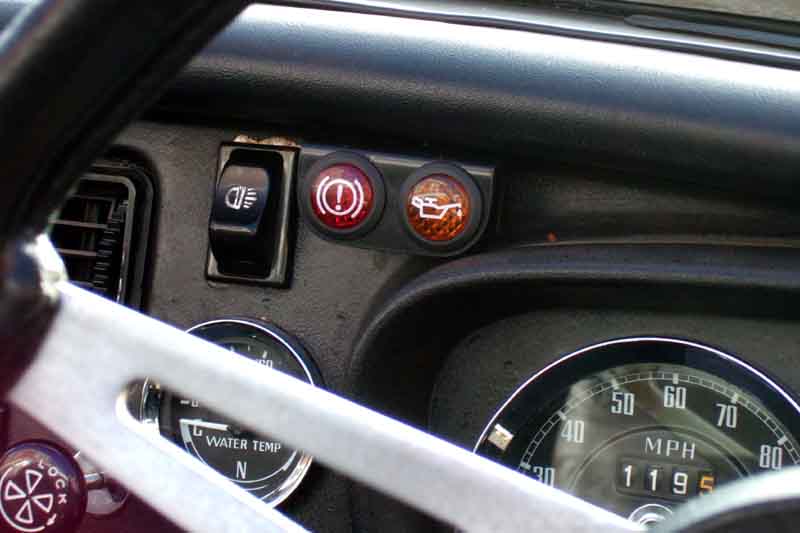
... and on in bright but not direct sunlight.
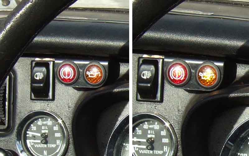
However less visible in low direct winter sun - off on the left, illuminated on the right. Maybe a cowl? They are angled towards the driving position.
First fitted over a year ago, and it's been working fine ever since, and the fluid level hasn't dropped enough to set it off. Also no apparent change in the polypropylene float or other plastic components. Time to make one for the V8 as well. Going back to the squawking problem I thought that if I ran the electronics at a lower voltage, I could get them to ignore the voltage fluctuations caused by turning other circuits on and off. So got another set of components on a bread-board, powered those from 12v, and tested it on both cars to confirm I was still getting the unwanted son et lumiere which I was. I found a data sheet for the IC I was using which said it operated from 4 to 15v. I had a 5v zener diode and used that with a suitable resistor and capacitor to produce a regulated and smoothed power supply to power the electronics. It didn't work with the resistor values I had originally chosen, which didn't surprise me as now it was running at less than half the voltage. But try as I might I just could not get the circuit to switch, no matter which of the input voltages was higher than the other. I wondered if I'd blown the chip so put it back to 12v and the original values, and it was fine. Much pondering, head-scratching and testing, but no change. Until I suddenly wondered if a higher supply voltage might make a difference. Upped it to 6v - and it worked perfectly! The data sheet I had found was for a chip of that number, but from a different manufacturer, obviously mine needs a higher supply voltage. So I used a 7.5v zener diode which I also had in stock, to give something of a safety factor. After that it was relatively easy to find a set of resistor and capacitor values to give me the required switching and self-check beep. Back on the cars, no interaction at all on the roadster including when cranking, and on the V8 just a tiny flick of the LED (but no buzz) when cranking, so a result. By upping the power supply smoothing capacitor from 10uF to 22uF even the V8 flick on cranking was eliminated.
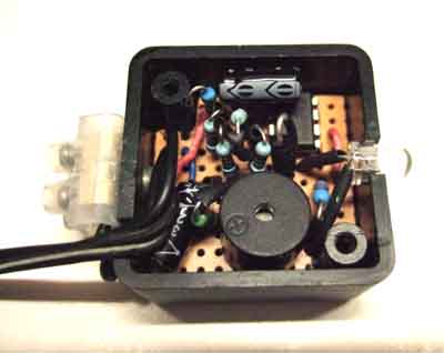 The sounder I'd used in the roadster circuit
was for 12v, but as I was planning to run it at a lower voltage I bought a 3v
version. I could have used a 6v, but the connections are easier running it in
series with the LED, that needs a series resistor anyway, and 27 ohms in series
with the LED and the sounder gives the correct voltage and current conditions
for both. That all fitted neatly in the same sized box as before, and the next
job was to design the component layout on strip-board. That proved easier than
the first circuit, with less linking and strip-cutting. I did need to buy a
second 22uF capacitor as I only had one in stock. Normally I get my components
from Maplin as we have a shop locally, but the last two times I've ordered
stuff online for collection, shown as available in that store, but they have
then said they don't have them. So ordered them from eBay - cheaper - but when
they arrive I find that instead of the dumpy type that I already have they are
taller and narrower and won't fit in the box standing up. Fortunately there is
enough room around the other components to lay them over, so building proceeds.
When complete I bench test - and the buzzer and LED are on all the time, even when
I simulate the switch being closed. I'd built the circuit-board version using
the same components that had tested OK on the bread-board, precisely to avoid
problems with different tolerances of different sets of components. I wondered
if I had damaged the IC from heat by soldering it direct into the strip-board,
which I had to do to make space for the laying down of one of the capacitors.
Testing the voltages at the IC pins in both switch open and switch closed modes
I found that touching the meter probe on one of the pins was enough to cause it
to switch off, and removing the probe it stayed switched off. Testing the
voltages on the two inputs instead of there being a clear difference between
switch open and switch closed, as I thought I had done on the bread-board, I
found the switched input voltage was only fractionally lower than the reference
voltage, when it should have been about 1v lower, so it looked like a marginal
signal voltage problem. Fortunately the input resistor was accessible, and relatively
easy to swap for a lower value to give a bigger voltage differential, and all
was well.
The sounder I'd used in the roadster circuit
was for 12v, but as I was planning to run it at a lower voltage I bought a 3v
version. I could have used a 6v, but the connections are easier running it in
series with the LED, that needs a series resistor anyway, and 27 ohms in series
with the LED and the sounder gives the correct voltage and current conditions
for both. That all fitted neatly in the same sized box as before, and the next
job was to design the component layout on strip-board. That proved easier than
the first circuit, with less linking and strip-cutting. I did need to buy a
second 22uF capacitor as I only had one in stock. Normally I get my components
from Maplin as we have a shop locally, but the last two times I've ordered
stuff online for collection, shown as available in that store, but they have
then said they don't have them. So ordered them from eBay - cheaper - but when
they arrive I find that instead of the dumpy type that I already have they are
taller and narrower and won't fit in the box standing up. Fortunately there is
enough room around the other components to lay them over, so building proceeds.
When complete I bench test - and the buzzer and LED are on all the time, even when
I simulate the switch being closed. I'd built the circuit-board version using
the same components that had tested OK on the bread-board, precisely to avoid
problems with different tolerances of different sets of components. I wondered
if I had damaged the IC from heat by soldering it direct into the strip-board,
which I had to do to make space for the laying down of one of the capacitors.
Testing the voltages at the IC pins in both switch open and switch closed modes
I found that touching the meter probe on one of the pins was enough to cause it
to switch off, and removing the probe it stayed switched off. Testing the
voltages on the two inputs instead of there being a clear difference between
switch open and switch closed, as I thought I had done on the bread-board, I
found the switched input voltage was only fractionally lower than the reference
voltage, when it should have been about 1v lower, so it looked like a marginal
signal voltage problem. Fortunately the input resistor was accessible, and relatively
easy to swap for a lower value to give a bigger voltage differential, and all
was well.
I had pondered what to do about the connections to the electronics - a 12v and earth supply pair, and a switch pair. The first two were easy - just a length of 2-wire coming out of the box with a piggy-back spade on the 12v and a ring-terminal on the earth, going to the instrument voltage regulator which has a fused ignition supply on the B terminal and earth at its mounting screw. But the other two were a problem - I need some kind of connection that I can connect and disconnect relatively easily. I can't cable direct from the electronics to the float switch as one or other would then have to be pushed through the bulk-head grommet or some other grommet! The large grommet behind the master is a possibility, but I'm not keen, as it would also mean cutting a hole and slot in that for the cable. I could have a pair of wires coming from each and solder them together behind the dash, but that would mean cutting them if I needed to remove either switch or electronics. Individual bullets would be OK as long as I got the polarity correct (to keep the lower reed contact at earth). I had already used a 2-pin plug and socket on the short tail from the float switch, and made up a length of 2-wire with a matching socket for the electronics end, but they wouldn't push through the grommet. I can push the cut end of that through the bulkhead grommet into the cabin, but that still left me with the problem of how to connect to the electronics, and would need a second method of connection. I settled for a small 'chocolate block' connector attached to the back of the electronics box, which means I still have to be careful about polarity. In hindsight the best option would have been to have a long tail from the float switch with a crimp bullet on one wire and socket on the other (to maintain polarity) which would be easy to push through the grommet and be in the relatively benign environment of the cabin, and a matching socket and bullet on another tail from the electronics. But there we are.
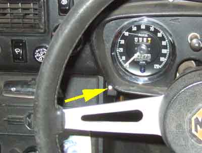
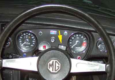 On the roadster I had stuck the box of
electronics to the side of the centre console, at the top, where the LED can be
angled towards me. But on the V8 with its wider binnacle the same place is
concealed by the binnacle. And a bit lower is concealed by the solid spoke on
the wheel in the straight-ahead position. Further down on the side of the
centre console is unobstructed, but moving further away from line of sight, so
I opt to stick it on top of the column cowl, alongside my coolant level
warning. A bit of a mish-mash with the coolant level warning, which was only
ever intended to be a temporary thing while I had a cooling system problem. I
fixed that years ago but could never bring myself to remove it. However the
area above the cowl on both cars does lend itself to positioning various
warning lights, I have in mind a purpose-built narrow housing that fits under
the dimmer rheostat and between the main dials, and would include an oil
pressure warning light as I have on the roadster. Just for the LEDs, the
electronics would be elsewhere to keep it as small as possible. The coolant
level warning has three red LEDs as at the time high-brightness ones weren't
available, are now in 'water clear' packages so only one would be needed.
On the roadster I had stuck the box of
electronics to the side of the centre console, at the top, where the LED can be
angled towards me. But on the V8 with its wider binnacle the same place is
concealed by the binnacle. And a bit lower is concealed by the solid spoke on
the wheel in the straight-ahead position. Further down on the side of the
centre console is unobstructed, but moving further away from line of sight, so
I opt to stick it on top of the column cowl, alongside my coolant level
warning. A bit of a mish-mash with the coolant level warning, which was only
ever intended to be a temporary thing while I had a cooling system problem. I
fixed that years ago but could never bring myself to remove it. However the
area above the cowl on both cars does lend itself to positioning various
warning lights, I have in mind a purpose-built narrow housing that fits under
the dimmer rheostat and between the main dials, and would include an oil
pressure warning light as I have on the roadster. Just for the LEDs, the
electronics would be elsewhere to keep it as small as possible. The coolant
level warning has three red LEDs as at the time high-brightness ones weren't
available, are now in 'water clear' packages so only one would be needed.
First time out it does what it is supposed to, but as we arrive at our destination and switch off I think I hear a slight noise, which could be from the buzzer as the power is cut. Back home when switching off I don't notice it, but turn the engine on and off a couple of times while looking at the LED, to see a very brief flick but no sound (the same thing happens with my alarm LED when I turn the main power switch off). That's fine, but on the second switch-on instead of the normal self-check beep it barely makes a noise! Rapping it with a knuckle during the beep phase makes it sound correctly, so it sounds like an iffy buzzer. However next day when everything is cooler it's back to working normally again, so it sounds like a heat thing. Subsequently I change the buzzer, and in some pretty warm weather it sounds as it should.
Eventually I do add an oil pressure warning light to Vee and even though the additional warning LED is quite neat in itself the three together are a mess, and even more eventually I get round to making a panel just for the warning lights and put the electronics behind the dash.
Brake fluid conductivity: As mentioned above some brake fluid I tested did conduct as shown on an ohmmeter, however how much of this is due to the fluid itself and how much to any moisture it might have absorbed since I bought it I didn't know. There are many home-use brake fluid testers about which do use conductivity to measure moisture content, however this Brake Engineering page warns against their use. Fluids vary in their conductivity depending on whether they are DOT3, 4, 5 or 5.1 and also between manufacturers. So unless the tester is calibrated for a specific fluid, the indications can not be relied upon. Brake Engineering says that only by measuring the boiling point can you accurately gauge moisture content, and that is a pretty specialised piece of kit.