
Previously replaced in 1994 I foolishly opted for an after-market roller-bearing release-bearing. As recounted elsewhere almost from the start it was making squeaking and wittering noises, then graunching noises in 2014, and finally this year I noticed it was dragging the idle down i.e. had seized. As this means excessive wear would now be taking place I started keeping a close eye on the clutch fluid level, as that is a good indicator of the wear. Finally the wear got to such a point that the slave cylinder started weeping, presumably the piston and seal having moved along the cylinder to a place it had never been before, possibly rough or corroded, where it couldn't seal. So that's it, change due.
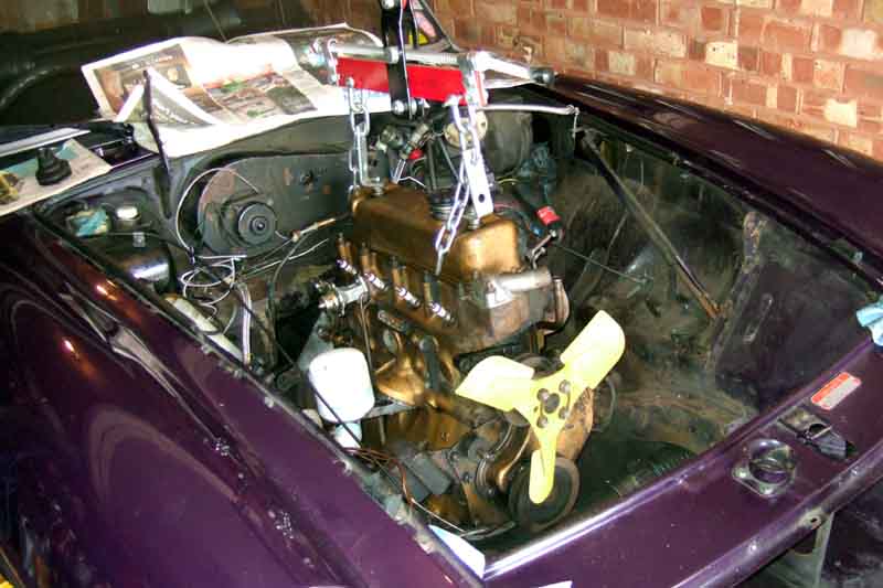
I borrowed the same hoist as for the 2008 change, although as this would be done in a single-width garage there was no opportunity for lifting the engine from the side of the car as I'd had to do for the rubber bumper as the arm wouldn't reach the middle of the engine. Hopefully being chrome bumper it might reach ... but no, so the bumper and grille have to come off, and when horizontal the end of the arm reaches just past the middle of the engine, which is a relief. Another consideration doing it in the garage is do I have enough clearance to the ceiling to lift the engine over the slam panel. Up and over garage doors would reduce the available height still further, but as mine is a double-length garage I'm doing it in the middle so well clear of the open door. This also gives me plenty of space at the back for removed parts, and plenty at the front for the hoist and engine when it is removed so I can just shut the door on it all at night. The front of the car will need to be raised to get at the lower bell-housing bolts at the very least, again reducing the available space.
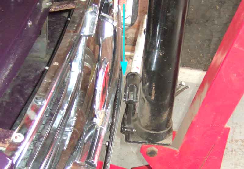
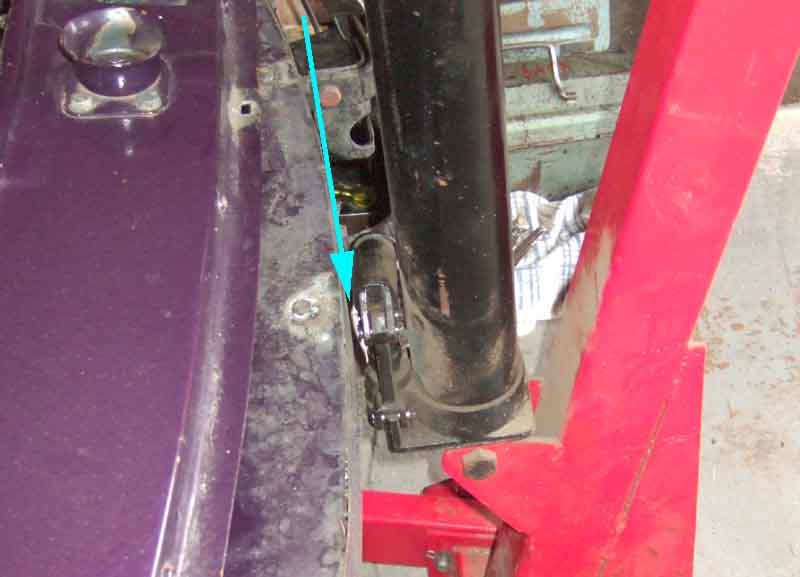
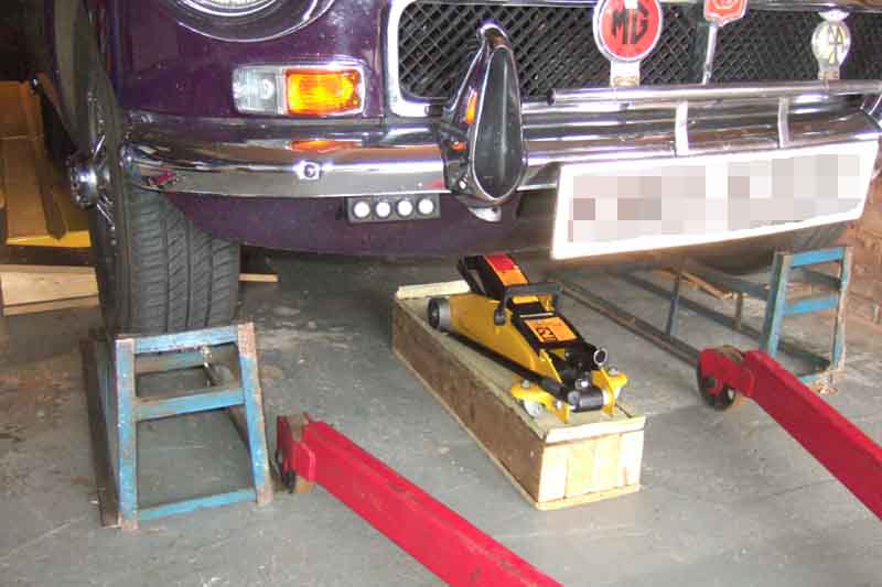
With the car in the middle of the garage the back wheels are on the lowered full-length ramps which raises it just enough to slide under to get at the middle exhaust clamps. It's quite close to the wall that side so reaching under from the side isn't an option. As I've previously found the drive-on ramps skid on the concrete floor if I try to drive up, I jack up the front of the car so I can slide them under the tyres. This hoist fits between drive-on ramps under the front wheels of the car, but the available height reduces still further as you take the weight of the engine on the hoist and the body rises on the suspension. A large hoist with long legs with the ends wide apart may not fit between drive-on ramps, so you may have to use axle-stands further back under the chassis rails. This will eliminate the problem of the body rising on the suspension as the hoist takes the weight of the engine, but I preferred the security of the ramps.
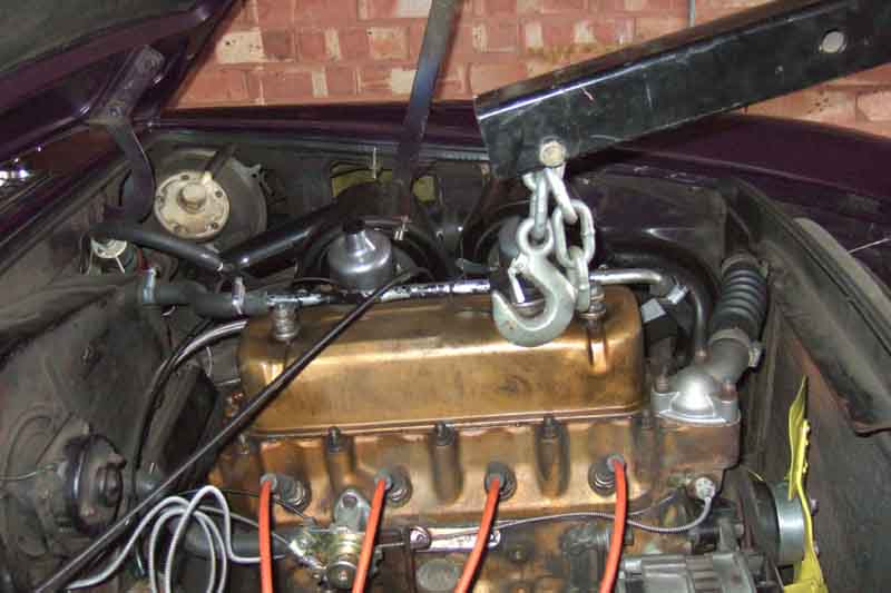
This time a leveller had been supplied with the hoist, but as that increases the distance between the end of the hoist and the top of the engine the arm has to be raised higher, and that brings the point of lift forwards from the middle of the engine as well as closer to the ceiling, so I decided to use the tow-rope under the front and the back and crossed over on top as I had before.
Then it was a steady plod disconnecting/removing everything. But first I redrilled the holes in the bonnet hinges to aid reassembly - they were on both pieces but didn't line up. Don't know why as alignment has always been good. Then a pal came round to help me lift it off. Next was bumper complete with number-plate and badge-bar, and grille.
I removed the air-cleaners, carbs and inlet manifold. On the bench the inlets of the carbs are uppermost, so they are plugged with a twist of clean paper. The crankcase ventilation hoses are removed, the fuel supply and servo hoses are tucked out of the way as well as the disconnected accelerator and choke cables. For the choke rather than undoing the inner clamp screw on the front air-cleaner bracket, which makes it a right fiddle getting the splayed strands of the inner back through the trunnion hole, I pulled the split-pin and disconnected the outer from the choke interconnecting lever. I removed the near-side engine restraint bracket, which has the carb overflow pipes attached to it, as an assembly. I have a solenoid valve in the vacuum line from carb to distributor so that comes off with the tubes as an assembly.
I had thought about disconnecting the exhaust manifold from the head and with the front, middle and back supports slackened pulling it across to the side of the engine bay. I did that for the head gasket change, but looking closely it seemed it wouldn't give me much clearance if any to the flange at the bottom of the block, and I didn't want to make things any more difficult for myself than needed, so opted to remove the down-pipes from the manifold. A 3/8" socket on extensions and with a UJ reached all the nuts easily, and I was surprised at the good condition of nuts and studs, although they had been replaced when this manifold was fitted in the early 90s. However three studs came out with the nuts. Getting the down-pipes out of the manifold was another matter! I had to wedge a piece of timber across the top of the pipes and under the chassis rails, lift the engine until that bowed, then hammer down on first one pipe and then the other with another piece of timber and a lump hammer. But that couldn't be done until I had disconnected the engine mounts. Shortly afterwards I came across someone who had done it leaving the manifold on the down-pipes, which is definitely easier.
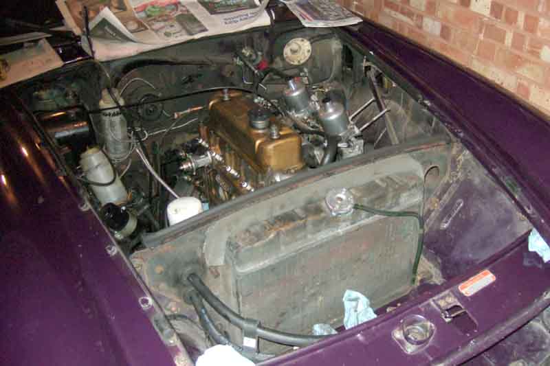
Removed the bottom hose from the radiator, with a large padded envelope under it to guide the coolant into a bucket rather than it going everywhere. Rather than pulling it off and everything rushing out, with the clamp slackened and pushed out of the way I wedge a screwdriver in the joint to create a small gap for it to trickle out, getting on with other things while it does so. Remove top and bottom hoses, and heater hoses - remember to open the heat valve when draining! Also the heater return tube from the rocker cover studs, just to get it out of the way.
Disconnected the oil gauge pipe from the block, then the cooler hoses from block and filter adapter, and remove the radiator, diaphragm and cooler as an assembly (over-slung cooler on CB may be OK, but you wouldn't want to hit it with the engine. Under-slung on RB can be left along with the diaphragm). Hoses need to be held up or positioned over containers to catch oil, and the filter adapter port needs to be plugged or a container positioned under it as unless you remove the filter first that will drip slowly but steadily the whole time. Plug and cover the oil connections on the block to stop anything falling in - I used the cut-off end of an old cooler hose and the old gauge hose.
Remove the temp sender from the head, removing the lower bolt from the heater tap to release the support bracket, and carefully tuck the capillary and bulb out of the way.
I had pondered leaving the starter on the engine, but it looked like it might foul the rack-shaft when pulling the engine back, so again opted to remove it to avoid making things more difficult than they need to be. That needs the distributor to be removed, which I do complete with clamp-plate, again plugging that hole. The bottom starter bolt needs a socket on an extension as the clutch hose is in the way, although you could disconnect that from the bell-housing first (it's been said that hanging down the spring can push the piston out and you lose the fluid, but I and others haven't found that). Top bolt is easy to access from above, then the starter can be pulled back and angled to lift out from above. This is with the inverted canister oil filter, the earlier hanging filter arrangement may be different.
Incidentally the two starter bolts are different on engines attached to 4-synch gearboxes. The upper one goes through the engine back-plate and into the bell-housing, so is longer. The lower goes into the back-plate only so is shorter. If a long bolt is fitted here it can foul the flywheel. However there is confusion over the thread type. The Parts Catalogue indicates they are both UNC thread; Brown & Gammons indicates they are both UNF; Moss Europe indicates the longer upper is UNC and the shorter lower is UNF. Moss makes the most sense - bolts that go into alloy castings are usually UNC, and those that go into steel are UNF.
Alternator has to be removed to get at the off-side engine mounting nuts and bolts. Annoyingly, a couple of the nuts and bolts are non-standard and fractionally bigger across the flats, so my 1/2" ring spanners won't fit, and the open ends have to be wiggled on and off. There is often a spacer plate under the near-side mount - don't lose it!
Just the bell-housing bolts left. I remove the top, upper side (the upper starter bolt also acts as the upper off-side bell-housing connection) and lower side nuts leaving the bolts in place to act as guides, and leaving the lower nuts until last. As you are lifting the engine initially with the gearbox attached to get the gearbox to the top of the tunnel, these are all that are required to keep the two halves together.
Incidentally all bolts removed from tapped holes, and nuts from studs go back in and on so they don't get lost or mixed up. That pretty-much leaves just the engine mount nuts, washers and bolts to be fitted together and those and the bell-housing nuts and washers to be kept in a safe place.
Now ready for the main lift. The front mountings come free with a bit of a bang, and I lift until the bell-housing reaches the top of the tunnel. Once there I jack under the bottom of the bell-housing to keep it wedged up there, and the lower bell-housing nuts can be removed, again leaving the bolts in place to act as guides.
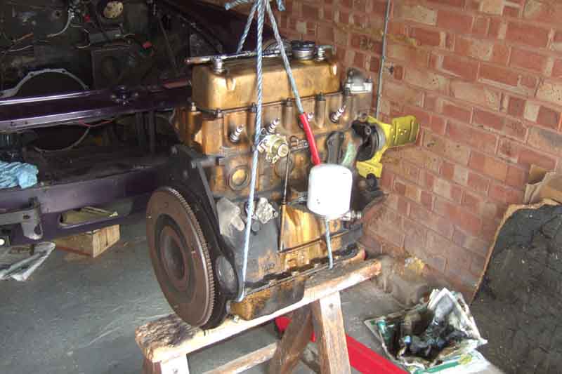
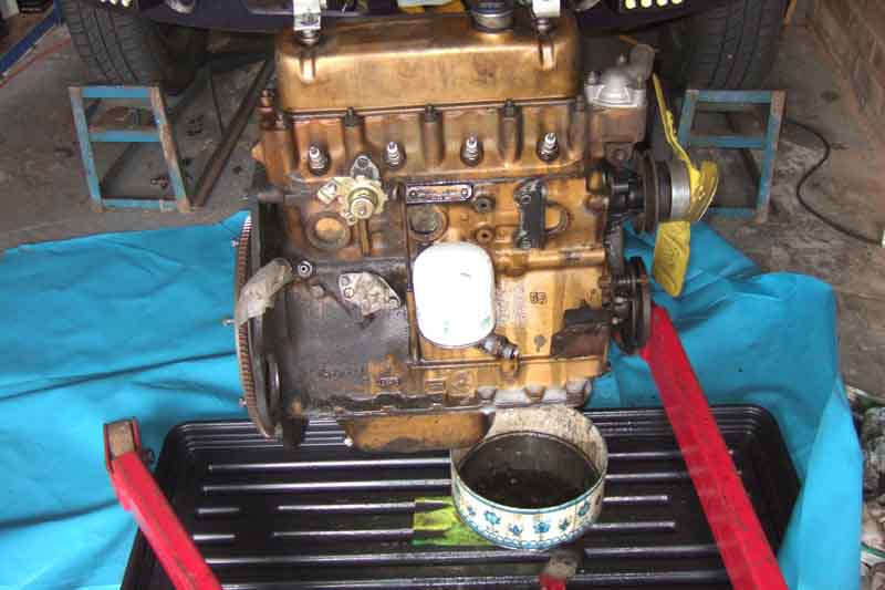
Which leaves the separate. Pull the engine back, only to find that the sump hits the cross-member before the end of the first-motion shaft clears the cover plate, so I can't lift it straight up, which didn't happen with the rubber bumper. Don't think about it too much at the time, and lifting and wiggling does eventually get the engine up and out, pulled forward clear of the front of the car, and lowered onto my saw-horse for additional support. (Subsequently asked someone else who had just pulled a CB engine without mentioning this problem, and he said he had the same thing. I wonder why no-one has every seen fit (in my sight) to mention this before). While doing that the pilot bearing came out of the crankshaft, which I wasn't expecting, normally people have to resort to some quite ingenious methods if changing that with the clutch. Personally I don't think it should be necessary, the only time that bearing is getting any wear is when you are in gear with the engine running and the clutch is fully or partially disengaged.
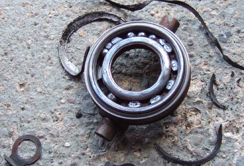
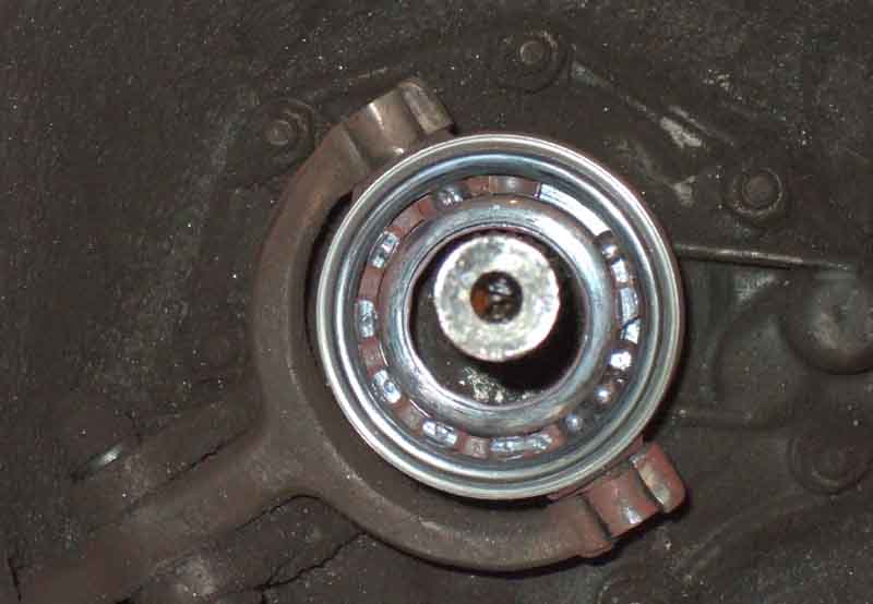
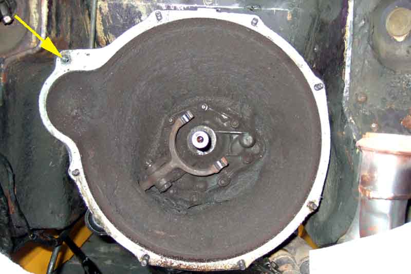
First sight of the release bearing and cover plate - and it is shocking! Bearing completely knackered with balls jammed and them and the housing ground down, the boss on the cover plate practically worn right through, and the ends of the diaphragm springs showing blue from excessive heat, and some partially cut through from the outer corners of the release bearing fork. No-one could accuse me of not getting the maximum life out of it! The air-gun gets the cover-plate bolts undone without having to jam the crankshaft in some way, to reveal the friction plate, which is barely worn. If it hadn't been for that damned release bearing the clutch itself would almost certainly have lasted another 50k and 15 years or so. The flywheel does have a slight wear groove, from a previous friction plate having worn down to the rivets, but as it's been like that for the past 22 years I'll leave it as it is, not worth removing it and getting it skimmed. The inside of the bell-housing is well mucky of course, but dull dry dirt rather than the shiny wet-look of the previous two, so again I just check the gearbox front-cover nuts for tightness.
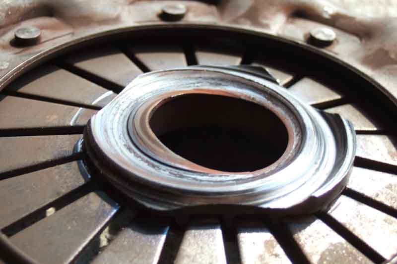
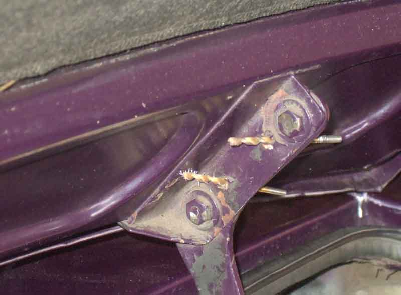
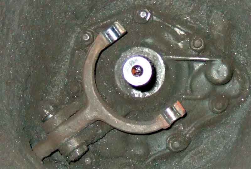
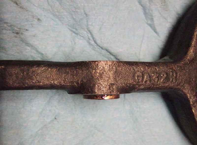
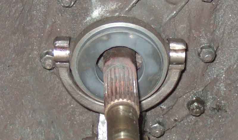
The other thing I notice is how offset the release bearing is to the first-motion shaft - sideways relative to the orientation of the release arm pivot bolt, getting on for 3/16". Even with the bearing removed the forks are still offset, and removing the arm and turning it over is just the same. I.e. it isn't the arm that is bent, but the pivot bolt bracket is not in line with the shaft. That's almost certainly what has caused the roller bearing to fail, which is why John Twist says roller bearings have a high rate of premature failure when used on a gearbox not designed for them. OEM applications like the Midget 1500, MGB GT V8 and modern cars, have a special carrier that keeps the bearing concentric with the shaft, compensating for any misalignment between arm and shaft.
Note the release arm pivot bolt is installed from underneath with the nut on top of the bracket, probably because the bolt can only be inserted from that side due to the design of the bell-housing and position of the bracket. V8 is the same:
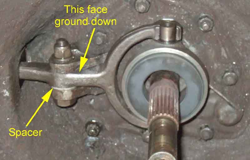
Not surprisingly I'm going to be using a standard graphite bearing this time, which are better able to cope with misalignment. However as the previous clutch replacement was caused by the release bearing casting wearing away and breaking, I'm wondering if the misalignment is so bad it caused that to fail, and so will cause the new bearing to fail. I find that with the pivot bolt nut slackened there is quite a bit of free-play between arm and bracket, and that tightening the nut would remove that free play to the point of the arm binding in the bracket, which was obviously too much. Adjusting the free-play in this way improved the alignment of the release forks to the shaft, but not enough to get an equal gap both sides. Note that this can only be done on CB gearboxes, RB gearboxes use a shouldered bolt which can only be tightened so far, leaving whatever free-play that exists between the brackets or in the bushing as slop.
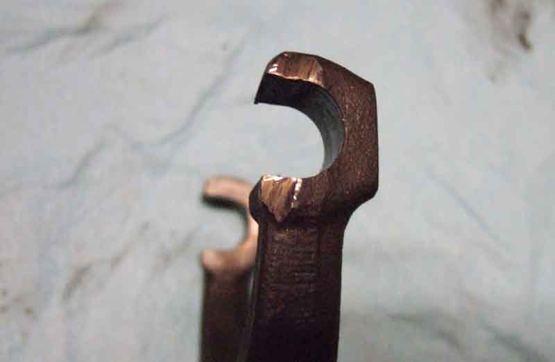
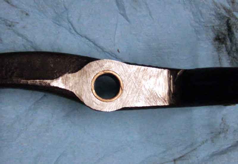
Pondering some time, I decide to grind away the boss on one side of the pivot point of the arm, and fit a spacer washer underneath. But before removing the arm I remove the clevis pin between it and the push-rod, and the slave promptly evacuates its boot, piston, seal, seal spreader and spring and all its fluid ... onto the floor before I can get a container underneath it. The garage floor is painted concrete, and hydraulic fluid makes an excellent remover of that as well as cellulose! Modifying the arm probably takes most of a day grinding, flatting, checking the thickness with a dial caliper at six points around the pivot bolt hole, and trial fitting with a 0.2" washer. I'd previously ordered a new bush and pivot bolt in case the old ones were well worn, but to be honest there didn't seem much difference. Nevertheless I used them, driving the old bush out with the double-socket technique in a vice, and pressing the new one in with the bolt. Of course the new bush was now longer than thickness of the arm, so I opened up the hole in the spacer washer to fit over the protruding end of the bush rather than grind it off. It made refitting the arm much easier, than trying to line up the holes in the washer and the bush to get the bolt through. Finally I tightened the pivot bolt nut to bring the new release bearing into concentricity with the shaft, as judged by the shank of a 8mm (I think) drill bit which just fitted into both sides, checking that the arm was free over its full travel. Note that as the release arm is moved back and fore the alignment of bearing to shaft varies in a longitudinal direction i.e. in line with the arm, there is nothing you can do about that. However - it was only subsequently that I realised if I had done nothing, and simply put a new release bearing and clutch in and they lasted the same as before, I would probably be over 90 before it needed doing again! Oh well, it's done now.
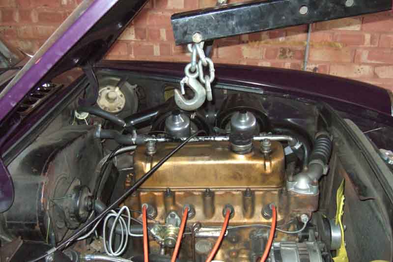
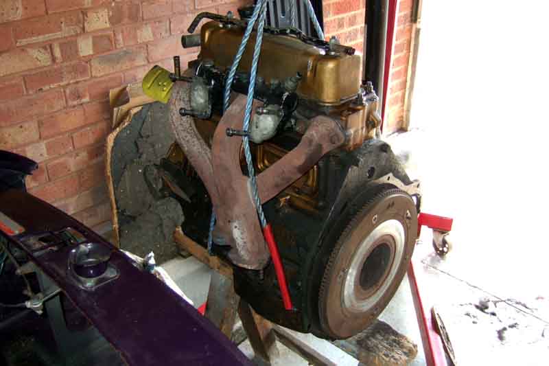
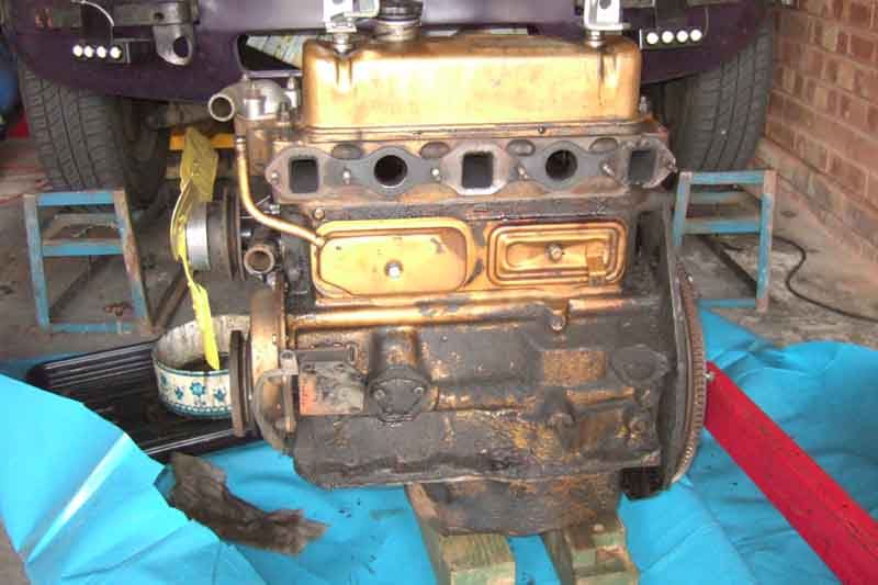
I'd contemplated tidying up the engine bay while the engine was out, but whilst I could have done the sides the back is so bad that short of removing everything it wouldn't have been worth it, so I left it. I could also have painted the radiator and diaphragm ... but where do you stop? (see 'Shipwright's disease'). However I did decide to clean the engine, as that was very dirty with thick crud from oil leaks having absorbed dirt. I couldn't do a proper job with my tow-rope still on, so I replaced that with the leveller attached to the rocker cover studs. I also removed the exhaust manifold to give better access. Engine cleaning probably took a day scraping, spraying with engine degreaser, working it with a brush, and wiping off. I couldn't pressure wash it in the garage, so laid a sizeable sheet of plastic DPC down, put a grow-bag tray (without drainage holes!) on top of that, then an old cake tin in that to catch as much of the crud and fluids as possible. I'd previously spent some time sealing the rocker cover, and also replacing the side cover gaskets and seals, cleaning around those areas at the time, and they had stayed clean so hopefully they were now leak free. The gunge looked a little shiny under the mechanical oil pump blanking plate, so I took that off and made a new gasket - the original looked to be paper. The near-side engine mount needs to be removed to properly clean that side, but the off-side doesn't obstruct. The off-side was so mucky I couldn't tell what had been leaking, although having previously replaced cooler and gauge pipes I was pretty sure they were sealed. Which left the distributor - of which more later. I covered that hole - already stuffed with paper - with duck-tape to keep displaced crud and degreaser out.
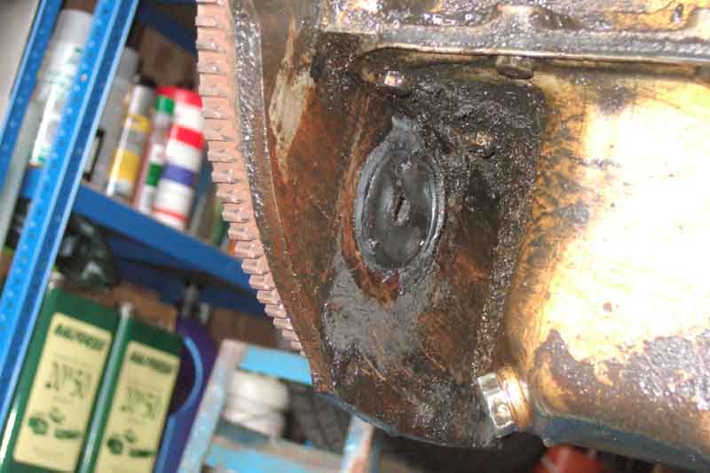
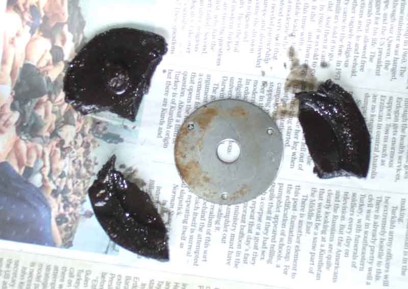
Whilst scraping the side of the engine back-plate that faces the sump, on the distributor side, some large lumps of what initially looked like underseal came off. Then I noticed it had revealed a large flat metal washer, and it turned out to be a very large grommet (12H 541) in a hole in the back-plate, the reason for which (the hole) can only be guessed at. That'll have to be replaced, so goes on a list in case I find anything else along the way.
With the manifold off I refit the three studs that came out on exhaust removal. Clamping them in a large vice I got the nuts loose, then with double-nuts could tighten the studs back into the manifold.
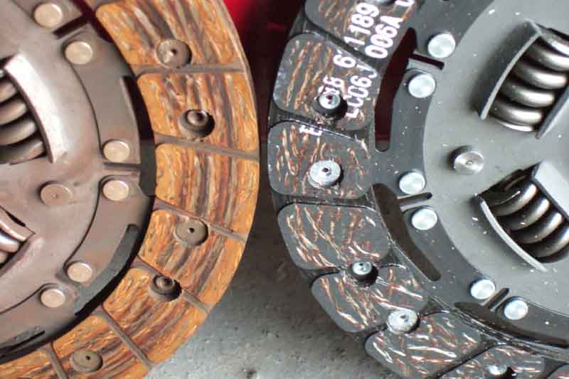
With the engine clean I can fit the new clutch! I check the friction plate fits the splines on the first-motion shaft. I also check the fit of the dislodged pilot bearing on the plain end of the shaft, it's not overly sloppy, so I refit it just tapping lightly with a suitable socket, whereupon it seems firm enough. Offer-up the friction plate on the alignment tool, checking that it is the right way round (friction plate butts up to flywheel, the wrong way round there is a big gap between the two), and loosely fit the cover-plate bolts. I'll need to hold the crankshaft still to torque up the cover-plate bolts, but a 1 5/16" socket fits the crank pulley nut well enough even with the lock-tab still in place, with a short breaker bar in that resting against the side of the sawhorse. Tighten and torque up bit-by-bit and evenly to 25-30 ft lb. As I do so I continually check the alignment tool is free in the friction-plate, if the friction-plate is fractionally off-set as you start to tighten the cover-plate bolts, it can wedge the alignment tool between the pilot bearing and the splines, which makes it difficult if not impossible to pull out. If it moves freely with the cover-plate fully tightened, then so should the first-motion shaft.
Clean the very mucky starter motor and its cable/wiring, and the not so bad alternator.
I'm changing the clutch slave and flex hose as a precaution. In 2008 we didn't bother but after the disturbance the slave weeped and was impossible to bleed. In the end we changed it and had planned to change the flex, but with the engine back in just could not get the pipe and chassis bracket nuts undone. So we had to reuse the old hose, but the new slave had a different thread start position to the old which meant that when tightened the slave wouldn't sit against the bell-housing without putting a twist in the hose. Fortunately an extra copper washer at the slave end brought it into alignment. I've opted for a braided hose, as for years and particularly when changing the master seals two years ago I ended up with a low biting point despite repeated bleeding using various techniques, and wondered whether hose swelling was a contributory factor. First thing is to undo the slave bolts - and they are tight all the way. They are also different to each other - one 1/2" with an integral washer, the other 15mm. When I get them both out I can also see the threads are different, so one of them has been forced in - presumably at a previous slave change as I can't imagine it being done like that from the factory. The bolts were quite rusty and cruddy, so I ran a hacksaw blade along both faces of the threads for the full length to clean them up. I wondered about using a tap to clean up the bell-housing threads, but didn't want to remove any metal, and in any case didn't have one that fitted either of the bolts so that was that.
Whether it was ease of access with the engine out, or they weren't that bad anyway, the pipe and hose nuts came undone easily enough, and the shiny bits go on. Screw the hose into the slave first, attach the slave to the bell-housing copper-greasing the threads, and making sure they go back in the same positions. Oddly the 15mm bolt goes in quite easily now, but the 1/2" one is still stiff. Then I can tighten the hose in the slave, and fit the hose to the pipe and chassis bracket, and refit the push-rod and clevis pin. The first thing I notice is that the wear in the clevis pin - which I had noticed earlier but ignored as the hydraulics compensate for any wear at that end (unlike wear at the top end which leads to a low biting-point). The pin didn't look too bad when out, but with the corresponding wear that must be in the end of the release arm the two are way out of line and looks really bad, so another part to go on another list, together with a release arm gaiter, as I've already ordered the engine back-plate grommet.
Then I notice that having raised the release arm on its pivot bolt by 0.2", the slave is not directly in line with it anymore - buggah! What to do? Put the release arm back in its original position by putting the washer on the ground down side? Which leaves the original misalignment and possible future release bearing problems? So I decide to modify the slave. It's alloy i.e. quite soft, so I opt to overdrill and file the holes somewhat in order to slide it across to closer alignment. It does mean that one has to hold the slave in the correct alignment while tightening the bolts, but it's not something I'm planning on doing again for a while yet ...
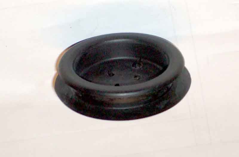
The engine back-plate grommet has arrived, I thought it might be a bit of a struggle sandwiched in the narrow gap between that and the sump, but it pops in quite easily. With that, the engine is ready to go back in.
Fit the seven UNF bell-housing bolts before offering-up the engine - there are three different lengths so if you removed them but didn't note which went where, as a rule of thumb when in the right places they should all project forwards by about the same amount as shown here, which also indicates the position for the upper UNC bolt for the starter. More info here.
I've already lubricated the release bearing pivots with the red grease supplied with the clutch kit, so apply more to the splined and plain part of the first-motion shaft, and the splines of the friction plate and pilot bearing. As I have removed the tow-rope from the engine for cleaning, if I refitted it for lifting I could no longer rely on it holding the engine at the correct tilt for the gearbox. But this time I have the leveller, so decide to use that. However that adds many inches to the distance between the arm and the top of the engine, which means the arm has to be raised higher, which means the reach into the engine bay won't be as much, and may reach the ceiling before the engine is high enough to clear the slam panel. I could lower the front of the car by taking it off the ramps, but that compromises getting at particularly the lower bell-housing bolts. I shorten the two chains on the leveller, and the one between the arm and the hook by as much as I can, and I do have enough lift to clear the slam-panel and ceiling at least, and push the hoist with engine forwards, lowering as I go, in small increments as the cover plate gets closer to the end of the first-motion shaft. The leveller also proves its worth to get the correct tilt, although as you vary the tilt you are also varying the fore and aft position of the engine, so all that has to be taken into account to avoid hitting the shaft. Also although you can move the pump-end of the hoist from side to side, because the arm is at its fullest extent, the engine is very close to the wheels on the legs, so the engine itself hardly moves from side to side. So if the leg wheels aren't in the right place, you have to back out, slide the pump-end across, and push back in. And then comes the problem.
Although I have the engine correctly positioned, when I try to lower the cover-plate past the end of the first-motion shaft, the front of the sump hits the cross-member first, which pushes the engine back, until the cover-plate is overlapping the end of the shaft. I suddenly realise this is the same problem Terry had. It wasn't a case of the pulley fouling the rack as I thought then because with the gearbox raised that is well clear. Fortunately the suggestions I made of moving the gearbox cross-member back and only putting the bolts back in the minimum amount to give more tilt did help, but Terry's still needed a shove to get them together. I didn't have this problem with the rubber bumper, then it struck me that they have the body raised on the modified cross-member, which means the gearbox when at the top of the tunnel will also be raised relative to the cross-member, and maybe that gives just enough clearance for the engine to be lowered all the way down before the push back.
However with the leveller I can over-tilt the engine i.e. clutch end down, till the cover-plate can go over the end of the shaft while the sump is still clear of the cross-member, which allows the engine to go back an inch or so, which gives more clearance between the front of the sump and the cross-member. I adjust the leveller, arm height and hoist position bit by bit in concert, sort of swooping the engine down, back and onto the shaft, until the engine is correctly aligned with the gearbox in terms of the shaft being in the middle of the cover-plate hole and there being the same gap all the way round between the engine and the bell-housing. I've got the gearbox in 4th so the shaft won't turn, and pushing back on the engine and with the pulley socket back on the nut turning the crank back and fore, the splines engage quite easily. Push back further and wiggle the engine so I can get the bell-housing bolts in the back-plate holes. The top starter bolt helps keep the two halves aligned as it can be screwed on from the front while you get the bolts bell-housing bolts through the back-plate holes, and pushing back further allows me to start getting the nuts back on. I get to within about 1/4" but with the leveller and the higher angle of the arm the hoist is as far back as it will go with the pump up against the front of the car. So with a combination of wedging a piece of wood between the pulley and the rack tube, and tightening the nuts bit by bit, I pull the two together. In hindsight if I had left the back chain on the leveller one link longer, I would have had to wind the leveller to move the engine forwards to get the correct tilt, which may have brought the two fully together. However that may have then compromised my ability to get the back of the engine raised enough to 'swoop' the engine onto the shaft.
With all nuts fitted and the bottom two tightened, I can remove the gearbox jack and lower the engine onto its mounts - phew! 'Just' the reassembly to go.
First is to get the top two engine mount bolts each side in. These go head up, thread down. Even though it is easier to get the nuts on the other way up, the excess thread sticking up compromises alternator adjustment on the off-side as well as the fitting of the restraint plate on the near-side. Remember to refit the spacer plate under the mount on the near-side. A bit of lifting and wiggling with just the bolts pushed through may be needed to get them all in, before you can fully lower and start fitting lock-washers and nuts, tightening them while you still have maximum access.
The exhaust was slightly fiddly, the clamping plates had slid down and I couldn't get the front one up past the sump flange. I couldn't pull the pipes sideways enough to get it past as the pipes were fouling the studs, so had to completely disconnect the front mount to bell-housing so I could push the pipes down, then sideways, then slide the front clamp-plate up. With the exhaust released that stayed there and I could get a couple of nuts started, and I could slide the back one up and get a couple of nuts on that as well. The ends of the pipes wouldn't go up into the manifold initially, and needed pulling and pushing back and fore and sideways. Then I could get all the nuts on and tighten them.
After that it is a case of refitting everything else, in reverse order. Well I say 'everything', but I wanted the minimum back on so I could run the engine and check the clutch before I went too far, discovered a problem, and had to remove it all again so wouldn't be putting the hoses or coolant back, connecting the heater valve, temp sender etc. So carbs, choke and accelerator cables, fuel pipes, crankcase breather and servo hose go back on. On the other side refit the starter and its cables/wiring. Then the oil cooler (and hence the radiator and diaphragm just loosely attached and the cooler resting on the apron) and gauge pipes, distributor static timed to 10 degrees, cap and plug leads. Then the dreaded clutch hydraulics filling/bleeding!
As the car was on its front wheels on ramps reverse bleeding from the caliper wasn't initially an option, so I went for conventional bleeding from the top with the EeziBleed. Pedal felt very light, with a 'dead' area near the top, so probably still air in there which didn't surprise me. I checked the push-rod travel by measuring from a flange on the master to the furthest edge of the release arm - first with the clutch pedal released and then with it wedged fully down ... and got 11mm or 7/16", which is less than the 1/2" I've always considered the minimum. Nevertheless I started her up, tentatively checked reverse and got grinding. Wasn't that surprised, but could select 4th, and whilst the biting point was low it wasn't that much lower than before, so rather bothered by the grinding. Switched off, and as it was near the end of the day wedged the clutch pedal fully down overnight.
Next day released the clutch pedal hoping to flush any air back into the reservoir, but travel just the same, with the same grinding and biting point as before. Buggah. It all gets a bit confused now, but by supporting the off-side spring-pan on an axle stand I can get the wheel off for reverse bleeding, and it is no better. Intending to drain only some out it took me by surprise and emptied, but then I've filled a completely dry system this way on the V8 and had a full clutch straight away. Move on to plan C and take the slave off letting it hang on the hose, and with a cross-point screw driver force the piston all the way in as far as it will go, with significant gurgling up at the master at one point which is promising. Refit the slave - aligning it to the release arm as before. Check the travel as before i.e. fully wedged down and fully up and still 11mm. Run the engine again and reverse still grinding, but paradoxically the biting point is now a lot higher. Double-bugger, the friction plate must be dragging on the flywheel or the pressure plate, or the first-motion shaft binding in the pilot bearing. I could take the engine out again, but what would I be looking for? Without mating it up to a bell-housing with a great hole in it I wouldn't be able to check anything. Eventually I decide to complete the job, and see what it is like on the road. One thing I had discovered along the way is that if I nudge it into first before selecting reverse, it goes in with just a slight crunch not the full grind. Also only partially operating the clutch pedal, or waiting with the pedal fully down before selecting reverse, makes no difference.
So fit the rest of the stuff except for bonnet (fitted with the Navigator who is always happy to help with 'clean' jobs), bumper and grille, fill with coolant, and take it up and down the road. Idle was very rough and lumpy, so check the setup to find the air-flow balance very close but the mixtures on both carbs needed richening by several flats for some reason - I'll check it again after some shake-down mileage. Biting point is very high - uncomfortably so, probably due to my extended master push-rod I fitted in 2014 in an attempt (only partially successful) to raise the biting point when I had all the problems bleeding after changing the master seals two years ago. Still crunching into reverse, reduced by nudging into first immediately beforehand, so I'll just have to get used to doing that every time, until I can see if it 'beds in'. Leave the pedal wedged down for another night - next morning no different.
Finally fit the bonnet, bumper and grille and take it for a few miles. It's so annoying, the new clutch is beautifully smooth and light, and no judder in reverse that the previous clutch did from new, just that crunch engaging it, and the uncomfortably high biting point. Post 'finally' I take out the extended push rod which lowers the biting point to a more comfortable level. I recheck the slave piston travel and it is still 11/12mm (but then so is the V8 checked at the same time), so I just can't understand why getting-on for an inch difference at the pedal isn't more visible at the slave. Swapping the cars round for these latest checks the roadster went into reverse with just a click, but then swapping them back it was more like a crunch again. So maybe it will get better with time ... or maybe not.
Post post 'finally', I get a free clutch pedal, with that fitted it should be back to standard. Well it certainly improved things, but still seems higher then the V8, but as pedal, piston and master-pushrod are all now as standard I'm not going to do any more with it.
Having cleaned the engine I've been looking carefully all round to see if I can see any oil escaping, and did see a small trickle under the distributor. Originally engines for Mk1 cars had an O-ring on the distributor shaft, then it was deleted for the rest of chrome bumper production, only to reappear again for rubber bumper cars which had the 45D4 distributor. Although the distributor for this engine wouldn't originally have had an O-ring, or even a slot for it, I decided to buy one to see if I could make use of it. On removing the distributor I was surprised to find a slot, then remembered this was a remanufactured unit and not an original. So O-ring fitted. However the block face the distributor clamp plate butts up to seemed clean, and there are a couple of plugged oil-ways immediately below that so it could be from there. But after a few dozen miles there is no sign of more oil, so O-ring it was.
A couple of years and a few k later I realise I'm no longer bumping towards first before reverse, and no noise at all if I have the clutch pedal down for a second before moving the lever.