


Contents
Index
So you think you want an MGB or V8?
Body
Brakes
Clutch
Cooling
Electrics
Engine
Fuel
Gearbox
Heater
Ignition
Propshaft
Rear axle
Steering and Suspension
Wheels and Tyres
Miscellaneous
Downloadable PDFs
The sectioned MGB at the British Motor Museum, Gaydon
Gearbox and Overdrive
|

Gasket sealants - don't use silicone-based as they 'go off' very quickly and on large areas will 'skin' before you can get the surfaces together and not spread out to an even thin coating. Use something non-hardening such as Loctite MR5922, and only a thin smear. Great gobs of it will get extruded out into the works and in the screw holes can rip paper/card/cork gaskets as they are tightened. Overtightening screws can cause covers to warp between adjacent bolt holes and leak more, check they are flat before fitting.
On the 4-cylinder 4-sync there are seven UNF bolts securing the gearbox to the engine - 'bolts' i.e. with a plain shank to give a dowelling function to correctly align the two. Different lengths for different gearboxes, more info here.
3-synch or 4-synch? June 2020
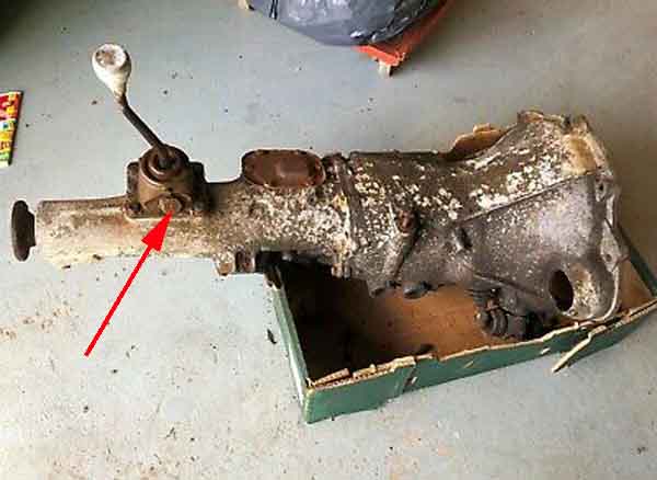
 Originally Mk1 cars were fitted with 3-synch gearboxes, and the primary recognition factor of those is if they crunch when you try to select 1st gear when moving, 4-sync gearboxes shouldn't do that. Reverse will crunch on both 3-synch and 4-synch. Mk1 cars are visibly recognisable from the tunnel which has a hump round the gear lever whereas 4-synch tunnels are flat. 4-sync gearboxes are occasionally installed in Mk1 bodies as they are more plentiful and cheaper than 3-synch, in which case the large removable panel on top of the tunnel has to be extended to move the gear lever hole back. However it's much easier doing that with a 5-main engine than a 3-main as described by Paul Walbran.
Automatic Gearbox Added December 2008
Starter inhibitor:
 There is a bullet connector in the white/red between the ignition switch and the starter solenoid (68 and 69 models) or the relay (70 and later) on Mk2 CB cars, which is where the transmission safety switch/starter inhibitor wires are connected when the automatic gearbox is fitted. It's just above the bracket for the clutch pipe and hose in the tail that leads down to the starter.
Kickdown cable:
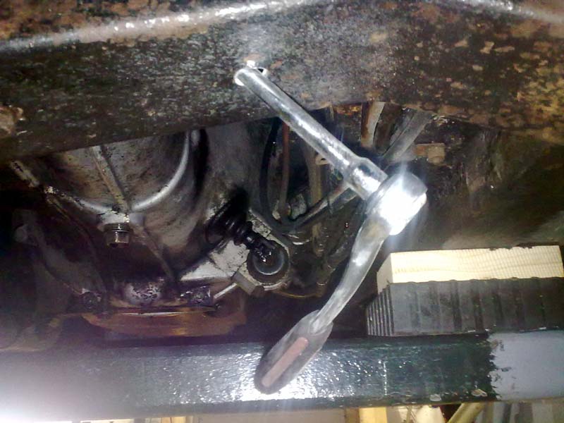
 André Wilding contacted me to ask if I could offer any advice in changing the kick-down cable, as the gearbox end seems to be concealed inside the gearbox, and where it goes in is concealed by the tunnel! I have no personal experience of changing one of these cables, but from the diagrams and descriptions in the workshop manual it appeared that the pan might have to be removed, which would mean draining the fluid first of course. Using that bit of information André took the plunge, and subsequently wrote back to me with the following:
"The 'cut-out' modification in the transmission tunnel is essential for getting to the screw in part of the cable where it goes into the gear box. Without it I think you would have to take out the gearbox etc. Even with it, it is a pig to get at and takes ages to screw in tight! Also, the hole is handy for getting at the reverse switch if something happens to it.
"Apart from that - it's an easy job!"
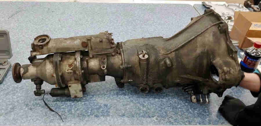
 Yes they are bolts i.e. with a plain shank for a dowelling action to endure correct alignment of gearbox to engine. It's not something I've looked at in detail but John Lewin in April 2024 was asking about this, saying that only two of the bolts are used to dowel into the engine back-plate as well as in the bell-housing - as indicated here on a 4-synch gearbox - but his aren't. He says the bellhousing and the back-plate have the correct smaller diameter holes in the dowelling positions with the others being larger, but his bolts don't have any plain shank protruding from the bell-housing in the dowelling positions. I can't find the bolts in the Leyland Parts Catalogue but Moss Europe indicate that that the dowelling bolts are the same as the non-dowelling bolts. In which case unless the bell-housing is thinner where the dowelling bolts are the shank must protrude in all the positions, and go into the back-plate, but will perform no location function in the non-dowelling positions. This is still going back and fore but it seems to me he has the wrong bolts.
Seven 5/16" UNF bolts of varying lengths facing forwards with nuts and spring washers for both 3-synch and 4-synch 4-cylinder, the V8 is different. For both 3-synch and 4-synch with the bolts fitted to the bell-housing there should be approximately the same amount of thread and a bit of plain shank protruding from each. For 3-synch there is one short BH605101 1 1/4", two intermediate BH605151 1 7/8", and four long BH605201 2 1/2". For the 4-sync there are four short bolts BH605221 of 2 3/4" round the bottom, one intermediate BH605241 of 3" on the side opposite the starter, and two long BH605261 of 3 1/4" at the top. Where the long bolts are at the top there may not be enough clearance to fit or remove them with the gearbox in its normal position so if they were removed with the gearbox out or pulled forwards make sure you replace them before it goes back! However with the other five bolts in and the engine on its mounts it should be safe enough to lower the rear cross-member (watch out for the speedo cable!) and that may tilt the engine and gearbox down enough. Leaving them in for splitting and mating means they can be used as guide pins to get the engine and gearbox 'square' to one another which helps get the engine and clutch onto the gearbox shaft.
V8: As well as there being eight 3/8" UNC bolts with spring washers there are two dowels for location, UNC as they screw into the alloy block (hence no nuts) so can only be accessed from the gearbox side. Four at 2 1/4" and four at 3".
 4-synch gearboxes of both types have a breather at the front left of the gearlever remote unit. 3-synch non-OD have one top centre of the tube on the back of the bell-housing which carries the gear change mechanism. However 3-synch OD don't seem to have the plastic breather, just a horizontal drilling at the right front of the gearlever remote unit.
Drive Flanges March 2017
V8:
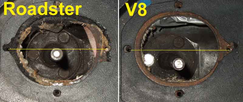
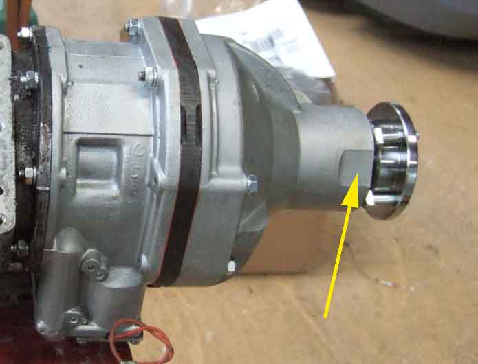 The V8 drive flange is larger, and that together with the flat on the OD casing allows the bolts to be removed with the flange still fitted. The V8 bolts are also larger at 3/8" UNF but otherwise have a similar domed, round head with a flat on one side.
Standard nuts and bolts on the rear flange.
All:
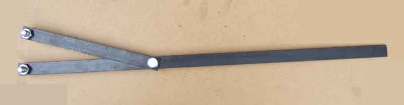 Before I realised I could remove the V8s bolts with the flange in position I thought I'd have to remove the flange. A pal made his own tool when changing the output shaft oil seal, but I knew that would not fit the larger V8 flange, so would have to come up with something for myself. I then suddenly realised I had made a tool to hold the cam-shafts and gears still when replacing the cam belts on the ZS, which should do the job. Made from B&Q flat steel bar (if their hardware is good enough for brain surgery it's good enough for me ...). It is a pivoting forked tool with bolts in the ends of the forks to fit holes in the cam gears, but with those bolts removed the holes are a perfect fit for two of the 3/8" bolts in the flange, to leave plenty of space for a socket on the nut. The long arm will rest against the edge of the tunnel (with protection) on the offside for loosening, and the near-side for retightening. The beauty of this tool is that it is universal, i.e. will fit any size of flange!
Gear Lever May 2017
Gaiter including jumping out of OD/gear
Removal
Anti-rattle bushes
 3-synch non-OD had a double-cranked lever set to the front of the 'stadium' (the correct name for a rectangle with rounded ends) on top of the tunnel. The cranking was necessary to get it closer to the driver due to the lever mounting position.
 3-synch OD had a straight lever to the rear of the stadium as the gearbox had 'remote control' extension which moved the lever further back, with a shaft from there to the gearbox shift levers.
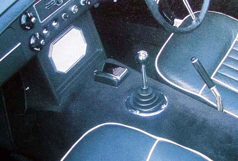 4-synch both non-OD and OD used the same 'remote control' extension arrangement so the lever was again straight coming from a virtually circular tunnel aperture, originally on top of the carpet, later on top of the centre cubby/armrest.
Knobs: May 2020
On Mk1 a pear-shaped hard knob, solid with engraved markings on Mk1 (1G3706 with locknut). On Mk2 initially a round hard knob with engraved markings (1B3736) then flat-topped with a plastic insert (making a stiff thread so no lock-nut) with the markings in 1973 (BHH788).
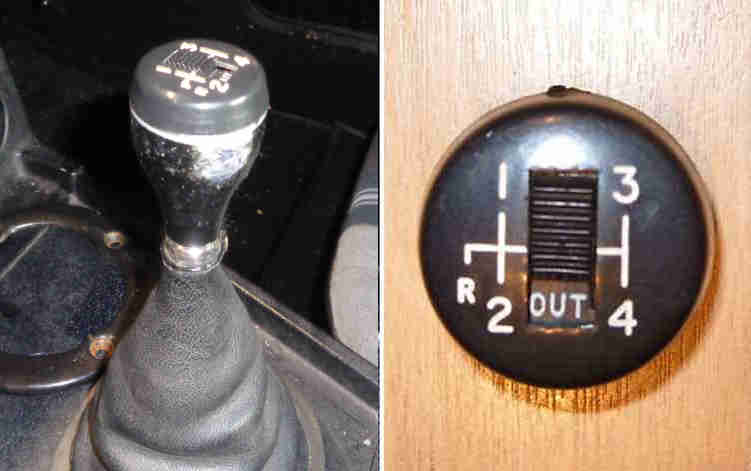 And finally for 1977 a different flat-topped knob with engraved marking and the overdrive manual switch comprising knob DAM2174, cone locknut C30505 under the knob, slotted nut C30623 inside the knob, and cap with OD manual switch BHH1900. A different cap was used for cars without OD having just the gear positions. A replacement cap for Geoff's GT was a very poor fit, loose instead of the ridge inside the cap clicking over the ridge on the knob, and with a new sub-harness to the switch just pushed the cap off. Eventually no less than three layers of insulation tape were needed on the knob to pack it out before the cap would stay in position.
According to Denis Welch Motorsport's 'Big Healey' site "Early 3 synchro gearboxes featured a 5/16 UNF thread (and a locknut under the knob), 4 synchro (66-76) have a 3/8 UNC thread (and a nylon insert in the knob so no locknut), whilst late (77 on) 4 synchro gearboxes have a 7/16 UNF thread" as they have a locknut again.
Gaiter:
Originally a ribbed rubber tube (3-synch) or cone (4-synch) coming less than half-way up the chromed lever. In 1972 with the advent of the centre arm-rest and cubby it became taller covering the whole length of the (painted) lever to the underside of the knob, comprising a ribbed rubber cone inside a vinyl outer, which is stapled to the flange at the bottom of the rubber. All were retained to the tunnel with a chrome trim-ring and four screws - self tappers on 3-synch, Pozidrive on 4-synch.
 Whereas 4-synch have basically a circular trim-ring for both OD and non-OD, 3-synch have an oval ring as the gear-lever is positioned further forwards on the non-OD box compared to the OD box.
October 2023: One long-held and oft-repeated fallacy is that the 4-synch trim ring has three long screws and one short one, with the short one going towards the front, as otherwise a long screw there can touch the gearbox and cause vibration and noise. That is how the screws should be, but the reason for the short screw at the front is that it screws directly into a welded nut under the removable panel in front of the lever which sits on top of the tunnel insulation, whereas the others all have to go though the tunnel insulation and tunnel to get to their nuts, so the shorter screw there doesn't need as many turns to tighten as a long screw would, and shorter screws are cheaper. For whatever reason Bee has three short screws and one long, with the long at the front as it happens, and it has never caused a problem with noise or vibration. Even when fully screwed directly into the access panel it's still about 1/2" short of the gearbox and after going through the trim-ring, leather and rubber gaiters and centre console it will be about 1" short of the gearbox - subject to gearbox movement when under way. Even short screws being used where long ones should be doesn't cause a problem in picking-up the nuts on Bee with cheap carpet, although thicker carpet and underlay may well need the longer ones. As well as moving the front screw even further away from the gearbox ...
Jumping out of OD/gear: After Vee's rebuilt engine and (unmolested gearbox) went back in 2017 OD has tended to disengage on the overrun, re-engaging when the accelerator was opened again, which it never did before. Suspecting the switch I took it out and sure enough electrical continuity was erratic as the plunger was operated. Fitted a new switch ... and it was just the same. The problem with the V8 is that OD is only available in 4th gear, and only starts closing as the lever is pulled back, whereas the 4-cylinder with it on 3rd and 4th starts closing as soon as the lever is moved across the gate towards the 3/4 plane. This means there is less travel of the mechanism inside the gearbox to operate the switch, so positioning is more critical.
As the switch is shimmed I started playing around with those - replacing the original 50 thou copper original with variously 45, 42 and 40 thou built up from a 40 thou fibre washer plus various front wheel bearing shims (which happen to be a very good fit). 40 thou ended up with the switch operated all the time i.e. in any gear which is obviously no good, 45 was the same as 50, but 42 seemed to work. However that is only 2 thou away from being on all the time, so a bit close for comfort. Along the way I discovered that if the lever were pulled back when it disengaged it would go back in, and with the thinner shims if I pulled it across the gate towards me OD would engage, even in reverse and 3rd - not right, but less of an issue than the 2 thou tolerance between working correctly and being on all the time.
Then in slowing down and speeding up traffic on the M6 coming back from the Lake District I discovered that when it did disengage - which wasn't every time, the lever would move forwards about 1/4", and if I pulled it back it re-engaged, as it did when I opened the throttle again. This is lever movement relative to the gearbox casing, not the whole gearbox moving around, which made me wonder if it was on the verge of jumping out of gear as well, i.e. worn synchro detents!
Talking to Roger Parker he suggested removing the gaiter, which I had already wondered about. But first I put it into each gear in turn trying to feel as best as possible just how much effort was required, and noticed that 4th seemed to need more than the other gears. Comparing it with Bee (handy having two) Bee did need slightly less effort, but it needed slightly more effort than Vee to take it out of gear again i.e. Bee's detents seemed stronger than Vee's. And in fact Bee has always tended to 'hang up' coming out of 4th occasionally, needing a second harder push. But that's another story.
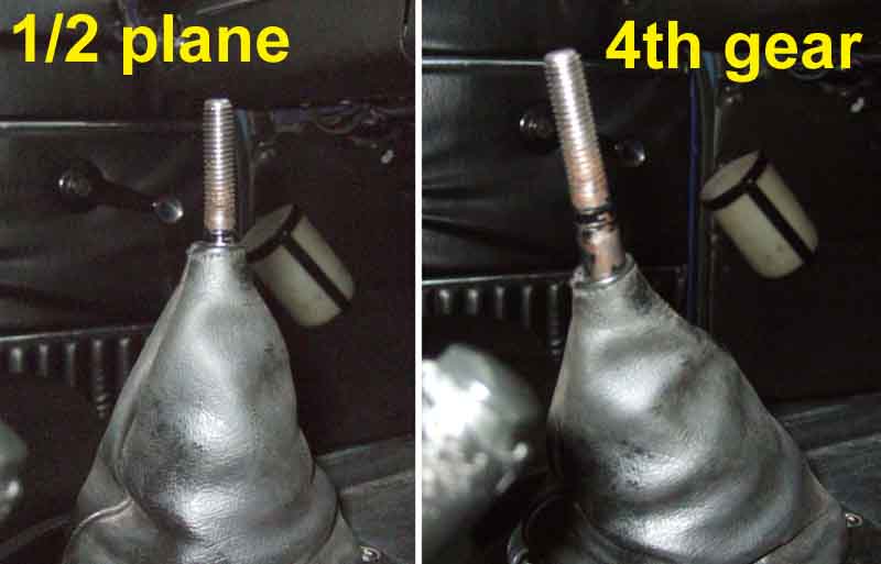 Next step with Vee was to remove the trim-ring from the gaiter ... and I was absolutely gob-smacked at how much easier the lever was to move in all gears, but especially 4th - 'light as a feather' springs to mind. Also the front left corner of the gaiter tipped right up in the air when 4th gear was selected, and manually trying to push it down again and pull the screw holes into line with it in 4th was almost impossible. So the gaiter is putting considerable force on the lever especially in 4th gear - so much for the age-old exhortation not to drive with your hand on the lever as it wears the linkages! The problem is that although the rubber is malleable, having the vinyl over the top means that when the lever is in (especially) 4th there is a bigger distance from just under the knob to the trim ring at front left, than when in neutral. The vinyl has no ribs and can't stretch, so it has to pull itself down the lever shaft, which means it has to push the rubber down as well. This is quite a snug fit on the lever, so doesn't slide easily. I thought about reducing the height of the rubber gaiter to something like the earlier ones with a couple of ties, but opted for some Vaseline on the shaft and inside the hole in the rubber gaiter. The result is a far lighter gear shift on Vee, especially in 4th, the top of the gaiter sliding down the shaft at least an inch. Something else Roger mentioned was that he has had the same problem when putting a 5-speed into an MGB, but put that down to the fact it was non-standard. On Vee, over a run of a dozen miles or so, accelerating and decelerating in 4th, not only did OD not disengage, but the tendency of the lever to ease forwards in 4th is very much reduced. Still there slightly, but when it does happen it's not immediately I decelerate but a few seconds after, and not as far.
 Something else I noticed comparing Vee with Bee with the gaiters off is that looking down on the gear lever, the tail of Vee's gearbox is noticeably closer to the driver than Bee's. Logic implies the middle of the H-gate i.e. the 1/2 plane should be central in the tunnel so the amount of movement of the gaiter is approximately the same in each gear, and if the knob needs to be moved relative to the driver then that is achieved by cranking the lever, as was done significantly on the 3-synch, only slightly on the painted 4-synch, and possibly not at all on the chrome 4-synch. Could be tolerance in clearances in the bolts and studs that form part of the gearbox mounting, I tried shifting the crossmember across but it made no difference. I also adjusted the engine steady bar to pull the top of the engine across to the nearside, wondering if that would pull the gearbox across a bit, but again not. That leaves the way the gearbox rubbers are attached to the gearbox and the crossmember, but short of a full hoist that's not really feasible to do anything about. I'm pondering putting a rubber bush between the drivers side of the tunnel and the tail of the gearbox! But that may generate noise in the cabin. For the moment gearbox positioning will have to stay as it is.
I'm leaving the switch with 42 thou for the moment, but because of my concerns of it being only 2 thou away from being on all the time, I moved the (PO-fitted) OD tell-tale from being on the manual switch to being on the gearbox switch, so I can see when OD is truly engaged, and not just showing that the manual switch is on, and try to remember to look at that when not in an OD gear, especially when about to select reverse. But next day I decided to go one step further and wire up a relay with a normally closed contact to the reverse light circuit, to give a second break in the OD circuit whenever reverse is selected. I'll still try and remember to look at the tell-tale when in other forward gears to check the positioning of the OD switch, give it some miles, and if it is no longer disengaging on the overrun will start upping the shims again.
But I'm also pondering mounting a micro-switch with a long flexible operating lever, on a bracket, screwed to the top of two of the lever retaining screws (drilling and tapping the heads), and using that instead of the original gearbox switch. With the switch mounted beside the lever, and angled appropriately, there should be loads of travel on the switch lever to ensure it is fully operated even when the lever moves back and fore slightly, but fully off when it is moved forward to the neutral plane.
April 2022: A thread on jumping out of 3rd gear on the MGOC forum. I'd commented earlier how much easier the lever is to move with the gaiter disconnected from the tunnel, and Dennis F said doing the same thing on his 1980 'solved' the problem. I posted pictures of my levers in the tunnels, which had them aligned with the side screw holes for the trim rings but showed both being offset towards the driver and Vee's noticeably more than Bee's which would account for how hard the gaiter it trying to pull the lever forwards and towards the centre. Dennis posted his but didn't take them from above so you can't see how much if any it is offset to one side, but it is almost an inch in front of mine, hence his problem in 3rd. He wondered if the engine restraint rod could be a factor and whether it could be used to pull the engine and gearbox back a bit. Initially I was doubtful, but then wondered if it had been set incorrectly and it was actually pushing them forward, so suggested disconnecting it to see if that let them sit back a bit. If so, as well as adjusting the restraint rod to get it 'right' he could also try using it to pull them back a bit more. Someone suggested engine mounts would be the cause, but whilst collapsed mounts (and more photos didn't seem to show that) would allow the front of the engine to drop, which due to the way the gearbox is supported would tend to move the lever forwards, the engine would have to drop an enormous amount to move the lever forwards by nearly an inch. Then Graeme Don said he'd had similar problems with his factory V8, tried removing the rubber gaiter but that made it far too noisy, so inverted it so the point of the 'cone' was right down at the gearbox instead of directly under the knob, which means there is hardly any flexing of the rubber cone in any of the gears and that completely solved the problem! However no help to Dennis as with a 1980 having the OD switch in the knob there is a large harmonic damper on the shaft meaning it could not be slid down the shaft to the bottom. Possibly fitted from the bottom, but would need more work, particularly with regard to the switch wiring, but I'll try it on Vee as a couple of times since the rebuild it has jumped out of 4th, although not out of OD.
 A bit of a struggle but I managed it, and it does seem lighter. I also notice now that when moved to the 3/4 plane it stays there, whereas before it used to come back about half way. I can also feel mechanical things happening in the gearbox as I move the lever, which in itself would not normally be desirable, but it does indicate that the stiffness of the rubber isn't damping them now where it was before. Pulled out the staples between the leather and rubber gaiters and slotted the rubber over the lever upside down, but because Vee's gearbox is offset towards the driver's side a little it took a bit of effort to push the corrugations down inside the tunnel that side, without that the ring did not get anywhere near the centre console. Dropped the leather gaiter over and tried fitting the ring but there is so little 'surplus' leather at the bottom under the ring it wouldn't stay there, so I had to re-staple it. Without the rubber to push the leather up and out it's not as 'fat' and it shows a bit more lever than before, but for some time I've had a couple of Land Rover finger-ring protectors from a factory tour as a souvenir on the lever under the knob so that takes most of it up.
Removal:
 Prior to 1972 gear levers have a gaiter that is secured through carpet to the top of the tunnel using a chrome trim-ring and four screws. From 1972 a centre arm-rest and cubby was provided and the trim ring screws go through that and the carpet into the tunnel. The 4-sync trim-ring screws have a shorter one at the front, said to avoid chattering against the remote control housing on top of the gearbox, but it's also going into a welded nut in the removable panel that sits on top of the tunnel, the other three have to go through that and some heat insulation and tunnel into welded nuts under the tunnel so the front one doesn't need to be as long as the others. Prior to 1977 the gear knob can be unscrewed and the gaiters (rubber only originally, then rubber with a leather cover) and trim-ring can be lifted off to expose the gear-lever retaining plate. From 1977 the gear knob is retained by a special nut, and cars with OD have the manual switch in this knob, with the wiring going down inside the gaiter. This wiring is prone to chafing and it is strongly recommended that a fuse is added to the circuit or severe wiring damage can result. Apparently it's not easy to loosen (or tighten, there are frequent complaints of buzzing) this nut so you may decide to deal with the retaining plate with knob, wiring and gaiters still fitted to the lever. Also on the 77 and later there is a harmonic balancer (large lump) on the shaft inside the gaiter so the retaining plate is slotted for removal from the lever.
 3-synch: There is a circlip that retains a cover in the remote control tower, and under the tower is a spring pressing down on the large ball on the gear lever.
4-synch: Remove the three shouldered screws (22B525) and Thackery washers (AJD7731, oddly on both my cars one of the washers was a standard spring washer).
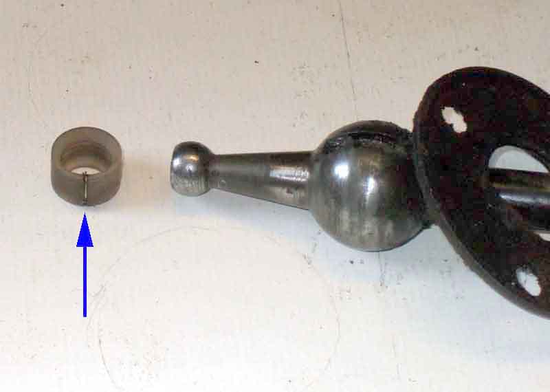
All: Lift the lever up and out, it may need a bit of a tug to pull the lever out of an anti-rattle bush that should be there, or the bush out of the remote control shaft.
Anti-rattle bushes:
Two of these (22H 15) are fitted - one at the bottom of the cabin lever and another at the end of the remote control shaft where it connects to the gearbox shift rods. If either of these bushes is missing the cabin lever becomes sloppy and will rattle about. It was only because my roadster has both that I realised when I got the V8 that at least one was missing. With the bushes, when the gearbox is in any gear, there should be virtually no free play in the lever at all. If you have free play in a gear, then the chances are that one or both are missing. The one on the lever is easy to deal with, the one for the shift-rods less so - with the 4-synch tunnel the gearbox would have to be removed, although you may get access on the 3-synch by removing the larger access panel. Fortunately only the one on the cabin lever was missing.
 There seem to be two possible ways to fit the bush - in the socket in the remote control shaft, or on the ball at the end of the lever. The first method resulted for me in the bush being pushed straight out of the bottom of the socket when I tried to push the lever into it. The second method starts off well enough as there is a split up the side of the bush, and it goes on the ball-end of the cabin lever easily. However when trying to push the lever back into the remote control shaft socket, it either won't go, or the bush will be pushed further up the gear lever shaft! That may be the case with a new bush, if reinstalling with an old one just tapping the end of the lever with a mallet may be all that is required.
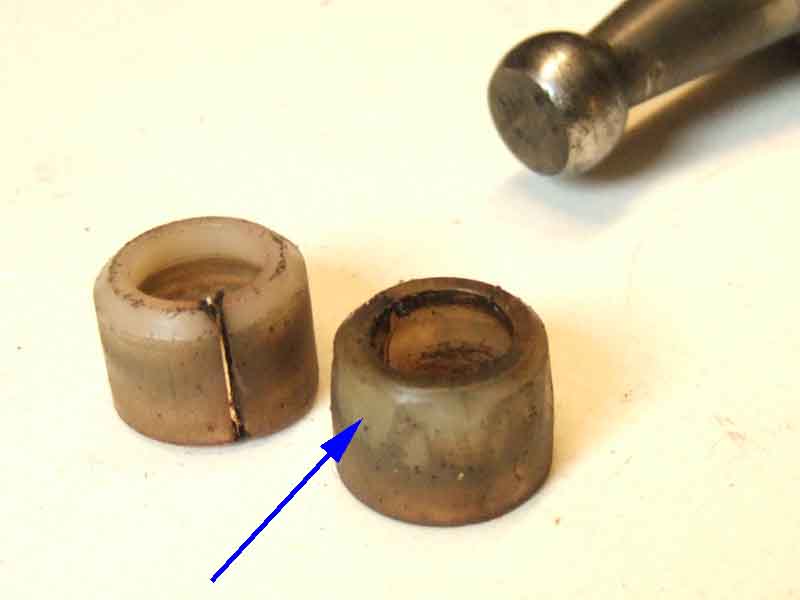 The new bush has a chamfer at the top which is presumably supposed to make this second method easier, but it is at far too abrupt an angle to help. I placed the bush chamfer end down, and used a craft knife to make a more gradual chamfer around the periphery, and it then went in.
 The same bush is used inside the gearbox and can only be accessed with the gearbox removed.
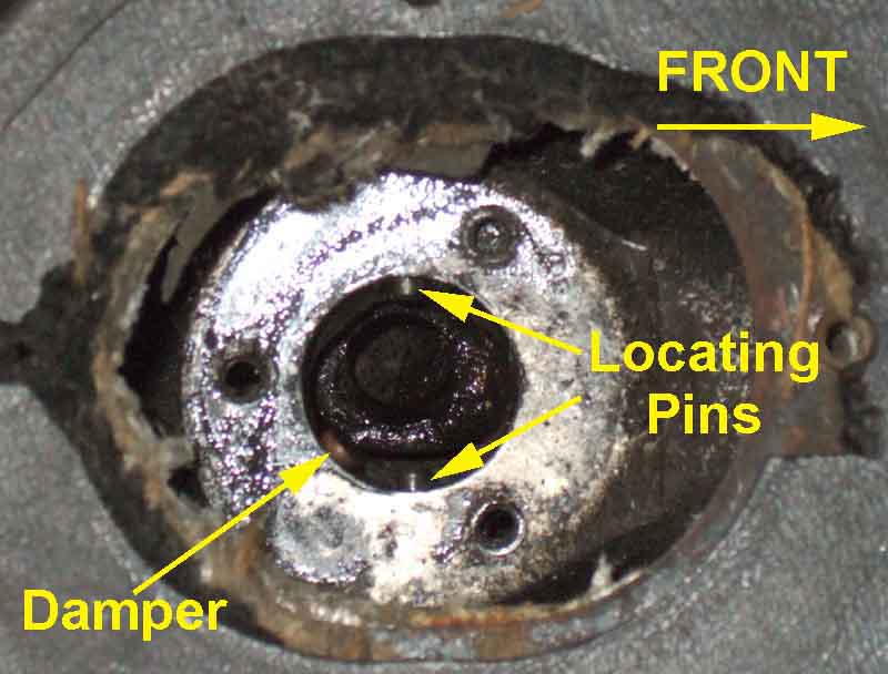 Both 3-synch and 4-synch (prior to 1977) have two locating pins screwed through opposite sides of the casing to protrude into the large socket, which engage with slots in the large ball on the lever. This allows the lever to move sideways across the gate and fore and aft into the gears, but prevents it rotating (but see below).
4-synch remote control towers have a sprung plunger going through the casing and pressing against the large ball on the lever. The Parts catalogue describes these as 'lever-damping' components, but as they have a sprung plate pressing down on top of the ball I don't know why it needs this additional damping.
3-synch OD have a 'plunger' at the gear-lever end of the remote control tower, but no indication as to what it is for. They have a single large spring pressing down on the large ball, which again would provide adequate damping, one would have thought.
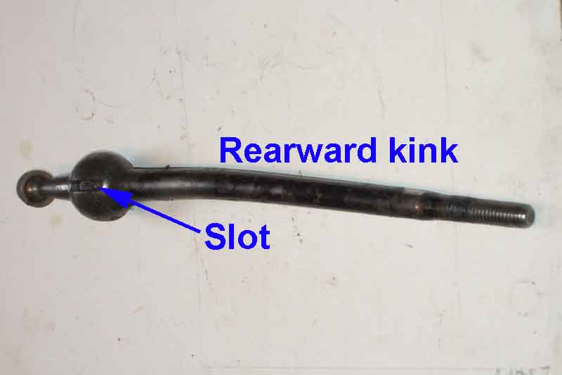 Because the levers have two slots it's probably possible to fit them either way round. The 3-synch lever has a double-crank rearwards so it's obvious which way round it goes. Clausager says that the 4-synch lever is completely straight, but there is a slight kink low down concealed inside the gaiter. It's less obvious which way round it goes, but it angles the lever rearwards.
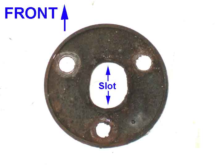 The lever seating plate has three holes so conceivably could go in any of three orientations. However rather than a hole for the lever it has a slot, and this is positioned fore and aft, meaning it can only fit one way. In the other two positions the slot would be diagonal. It also has a raised portion on one side of the slot, which goes on the left.
In 1977 all cars changed to having a slider switch in the gear knob, and another sub-harness down the gear lever connecting to the gearbox harness. There have been cases of this harness chafing and shorting out with the continual movement of the gear lever. As the OD is unfused this can seriously damage the other harnesses so fusing of the OD circuit is strongly advised.
 This type of gear lever has a significantly thickened section (said to be a harmonic damper but complaints of buzzing are legion) just above the retaining plate, so the plate is slotted to enable the two to be parted and reunited. Also this lever only has one slot in the large ball for location instead of one each side as previously, so only has one locating pin in the housing. At least it means you can't get it in the wrong way round!
October 2020:
 Bill Etter in America has just had a UK-sourced OD gearbox fitted to his 76. Supposedly from a 76 I noticed that the gear lever had been fitted the wrong way round so that it was cranked away from the driver instead of towards. Taking that out he found a spacer nut under one of the shouldered bolts through the plate that holds the lever in the gearbox instead of a Thackery washer (which is quite likely to be the cause of the stiffness with this box he mentioned), and no bush on the little ball at the end of the lever or in the socket. I also noticed that once out the socket only has a locating pin on one side, and no damper plunger - no big deal as he has retained the non-OD gearbox so it's just a matter of using parts from that. Whilst looking into this I studied the Parts Catalogues for changes in part numbers. North America is shown as having a different housing 22H1457 - but only from August 71 to August 72, when it reverted to the original 4-synch housing 22B522, all versions staying with that to the end of production. Now it is possible that is correct, and only one location pin was used (as the catalogue states) leaving an empty hole, but Bill's housing only has provision for the one locating pin on the right, there is no hole for one on the left, so it looks like he has a 77 gearbox not a 76. No big deal, it didn't come with the lever so he can use his original. The usual suppliers only show the one housing 22B522 albeit with the number of location pins reducing from 2 to 1 for the 77 model year, only one source states that the 77 and later housing was 22H1457. Quite possibly an error in the catalogues, but for the pre-77 catalogue to show that for 1971 then reverting for 1972, and the 77 and later catalogue still showing the original housing, is at least two if not three errors.
Gearbox Removal December 2019
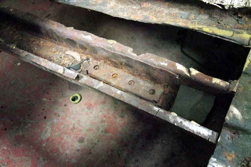
 With the possible exception of a non-OD 4-synch box (and that only with partial dismantling in-situ) you can't remove an MGB gearbox leaving the engine in place, because of the fixed crossmember under the OD (3- or 4-synch) or gearbox tail (3-synch). Some said they had seen a removable central section that looked so professional they thought it must have been factory, but if so it was certainly not used in production. I subsequently came across a couple of photos of just such a mod, although whether it is worth it given the number of times the gearbox needs to come out, or the engine to replace the clutch, is debatable. It would definitely make accessing the OD speedo cable easier though!
 The most obvious way is attached to the engine through the engine bay, but that is beyond me with access limited by a folding hoist and a single-width garage, albeit double-length. I've had no problem removing the 4-cylinder engine, and I was pretty sure I'd be doing the same thing if I needed to extract the gearbox, and remove that from under the car. When Vee's gearbox started whining about a year after getting back on the road after an engine rebuild - very annoying - I didn't want to send her away after the nightmare last time, but knew removing the V8 engine is nothing like as simple as the 4-cylinder for a variety of reasons. But one of my contacts put me onto a chap who knows these gearboxes, and has a V8, and he told me how it could be done. (Interestingly when I had - reluctantly - the gearbox converted to 5-speed by Vitesse they also removed the engine first then the gearbox even with a fully equipped workshop with lift and large hoist.)
If you are going to work on the gearbox or OD and need to drain the oil do the main draining before removal, then once out stand the gearbox on its bell-housing end - on blocks of wood not the end of the 1st motion shaft, and leave it like that for a couple of hours at least with the drain plug back in. Most of what is in the OD will drain into the main casing, then lay the gearbox down, remove the main drain plug, and be prepared for almost another pint.
January 2020:
 The gearbox comes back, and a couple of days later reinstallation commences. Five days after that all done, and a pleasure to be back driving her again.
How it works October 2017
| Another excellent explanation from Chrysler in 1936 of how a gearbox works, including synchromesh. It shows how 'gearing' occurs from the different distances from the centre of the gear to the tip of the teeth on each wheel, i.e. the relative lengths of two levers, the number of teeth on each gear just being a convenient way of expressing it. One thing that puzzled me for a while is reverse gear at 6 minutes and 50 seconds in. It isn't immediately clear that the reverse idler gear with two cogs is positioned in front of the 'counter' or lay shaft, at first glance it seems to be the same shaft with an extra gear. Thus the countershaft turns the reverse idler gear all the time, and the large sliding gear on the output shaft moves into engagement with the gear on the countershaft for first gear, and with the other end of the reverse idler gear for reverse gear. |
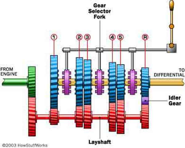 It's easier to see on this drawing from 'How Stuff Works' - which shows how all the gears are engaged. All the forward gears connect directly with the lay shaft, but reverse gear engages via the reverse idler gear, which being an extra 'wheel' between the input and output shafts reverses the direction of rotation of the output. In the MGB gearbox 4th gear engages the output (3rd-motion) shaft directly with the input (1st-motion) shaft to give a 1:1 ratio and the laygear is just spinning.
Interlocking Arm Assembly Added July 2010
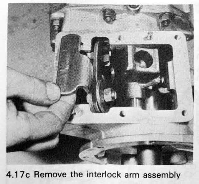 Stephen Stringer wrote to me while changing his 3-synch non-OD to OD. He had to obtain parts to build the OD gearbox up but couldn't find an Interlocking Arm Assembly. The 3-synch non-OD item is very different, the 4-synch looks similar and although it drops in the gears wouldn't select. As they selected with it not fitted Stephen was wondering whether he could leave it out, or if I could point him at a source for one. I don't know exactly what this part does but the word 'interlock' makes me think it is something to do with preventing two gears being engaged at once under certain conditions, which would be catastrophic. The part also seems to be NLA. Unusually the 'official' Workshop Manual and Parts Catalogues weren't that helpful as they didn't show both 3-synch and 4-synch for comparison (and in any case are only drawings i.e. only representative) and Haynes was the best source with a couple of photos that showed the part. From these I reckoned that a 4-synch could be made to fit, and Stephen subsequently reported that this was indeed the case. He says: "It's a simple mod, cut the mounting flange along the bend, move the cut off part back 4mm and reweld, that's it."
Internals Added January 2015
My V8 has always had this modification as the PO had the box rebuilt this way more than 30 years ago at around 100k, and I've had it done again recently after another 100k, not finding any issues in driving. Really you would need to get an unmodified V8, a modified V8, and a 4-cylinder and compare rpms at various speeds in 3rd gear to see how much difference it made on the road. Other differences are the front cover inside the bell-housing - the V8 item having a guide tube keeping the roller release bearing concentric to the first-motion shaft at all times, and the release arm is also different. The clutch slave cylinder is different (the bores in both that and the master differ to the 4-cylinder items), I don't know whether the mounting points differ. I do know that there was no problem changing the V8 flex hose with everything in-situ, whereas changing the 4-cylinder is said to be a pain, but that may be down to the position of the starter motor as much as anything else.
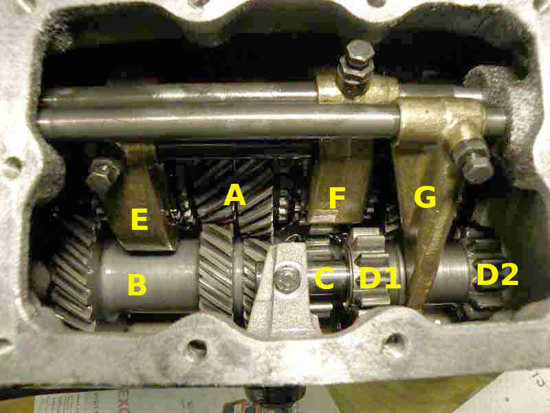 Michael Beswick gets hold of a spare gearbox and dismantles it for interest and information, plus dismantling and repair of a V8 gearbox.
Lubricants Added March 2014
The most important thing to be aware of is the correct oil to use, as the V8 is different to the 4-cylinder, and the V8 axle is different to its gearbox:
4-Cylinder
V8
Gear oil vs axle oil
4-Cylinder: The 4-cylinder gearbox and overdrive is straight-forward as it takes engine oil of the same grade as for the engine e.g. 20W/50. However this BL Technical Service Bulletin dated April 1975 says SAE 90 gear oil supersedes engine oil, although elsewhere there are unverified statements that it was subsequently rescinded. This British Automotive article (scroll down to 'Transmission oil') also states that rubber bumper MGBs used gear oil, although references to 'brass synchro rings' and 'non-synchromesh' are variously confusing and incorrect as brass synchro rings were only in the 3-synch - not 'non synchromesh' - gearboxes that predate this change. But Driver's Handbooks for RHD rubber bumper cars of two issues - up to 76 and 77 and later - make no mention of the change. If the 'GAJ-3/19/75' at the bottom of the Technical Service Bulletin is a date, then it would be an American document as it is in the month/day/year format they use and not the day/month/year format the UK uses. That tends to confirm the change was for North America only, although why, and how, when RHD and LHD were built at the same location can only be guessed at.
September 2025: A question has been asked as to whether 20/50 oil with 'high' ZDDP can be used in the gearbox as the poster had read that 'additives' shouldn't be used. The Leyland Workshop Manual emphasises it thus:
Gearbox and overdrive share the same oil hence the reference to 'gearbox' and the reason for the warning is that such additives can cause the overdrive to slip. ZDDP is usually referred to in connection with reducing wear in 'flat tappet' engines like the MGB, it does this by creating a sacrificial layer on highly loaded surfaces such as the cam lobes and tappets filling microscopic grooves in the surfaces so reducing wear in that way rather than with very slippery oils. Some American MGB owners do claim claim that anti-friction additives didn't cause any problems over many tens of thousands of miles, but then only around 17% of American MGBs had overdrive compared to 98% of UK models.
It's almost certainly the case that every oil suitable for the MGB engine will contain ZDDP at some level and as the manuals specify the same oil for the gearbox as well as for the engine then the simple answer is 'yes, oils with ZDDP can be used in the gearbox'. However the oil in question had ZDDP at 1500ppm, which is the highest I had come across, the previous highest being 1300ppm, and looking round the internet there are any number of sites (including oil manufacturers) saying 1000 to 1400 is a suitable range, 1200 is ideal, and above about 1400 or 1500 starts to cause increased engine wear from pitting and corrosion. On that basis I wouldn't use 1500ppm in either engine or gearbox.
The 3-synch gearbox takes 4.5 Imperial pints, 2.56 litres, 5.6 US pints and the 3-synch gearbox plus OD takes 5.33 Imperial pints, 3.36 litres, 6 US pints. The 4-synch gearbox takes 5.25 Imperial pints, 3 litres, 7 US pints and the 4-synch gearbox and OD takes 6 Imperial pints, 3.4 litres, 7 US pints. Note these are for clean and dry gearboxes, a drain and refill can be expected to take a little less than that as some oil is bound to be left behind, particularly with an overdrive.
V8: The V8 gearbox is different in that it takes gear oil instead of engine oil, to cope with the higher torque - 6 Imperial pints, 3.4 Litres. Some claim gear oil makes the V8 gear change very heavy in cold weather, but I used mine for several years in all weathers including several periods of well below freezing and didn't have any difficulties. The confusion may come from gear oil typically being SAE 80 or 90 whereas engine oil is typically SAE 20W/50, and some people describing those numbers as 'weights' which implies viscosity. They aren't, they are just arbitrary number ranges for engine oils and gear oils that don't overlap with each other. The reasoning behind this non-overlapping is to avoid confusion and people using engine oil where they should be using gear oil or differential oil which would result in rapid wear. The opposite may be equally damaging as the additives in gear and differential oils may harm the soft metals of the bearings. This viscosity chart from Precision Lubrication shows that 20W/50 crankcase oils almost exactly parallel 80 to 90 gear oils:

However it is equally important to know the difference between gear oil and differential oil.
Gear oils vs differential oils:
 To add to the confusion it is usual these days for manufacturers to refer to gear and axle oils by a GL number from 1 to 6. Usually GL4 and GL5 are used for passenger cars, and in most cases GL4 will be used for gearboxes and GL5 for axles, although in some modern cars GL5 is specified for gearboxes, perhaps where they contain the diff as well. GL5 oils are intended for hypoid-type applications most commonly found in axles, but a GL4 oil may be specified for axles that don't have a hypoid action. Some GL4 oils may be suitable for the rear axle, check they have statements to the effect that they are 'extreme pressure' or 'mild extreme pressure' and are suitable for hypoid axles. GL5 oils have additional anti-wear additives that can be harmful to some of the components in a gearbox designed to take GL4. Gear and axle additives are designed to coat the metal surfaces, and are 'sacrificial' in that it is the oil coating that is stripped away (replaced when the teeth go back into the oil bath or are otherwise sprayed) during use rather than the metal being worn away. But GL5 additives stick more tightly to the metal than GL4, and if used in GL4 gearboxes, when the additive is stripped away from softer metals it sticks so well that it actually takes a microscopic layer of metal away with it, even though there has been no metal to metal contact. This gives rise to another misconception of GL5 axle oils when used in a GL4 gearbox - that they in some way 'attack' the softer metals. But it's not a chemical reaction that dissolves the metal merely by being in contact with it, but the stripping action in use as described.
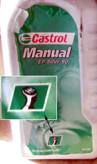
Both V8 gearbox and rear axle oils are typically based on SAE90 for temperate climates, but with the different anti-wear characteristics as described above, and different manufacturers describe their products in different ways. For example the Workshop Manual specifies Castrol Hypoy for the gearbox but Castrol Hypoy B90 for the axle i.e. 'Hypoy' in both cases. Esso equivalents are GP90 and GX90, but Mobil specifies GX90 for the gearbox and HD90 for the axle, so you can't rely on the letters to tell you whether they are for gearbox or axle. At the time of writing Castrol products are labelled a bit more clearly, as 'EP-90 Manual Transmission Fluid' and 'GL4' for the V8 gearbox and 'EPX 80W-90 Differential Oil' and 'GL5' for the axle in both V8 and 4-cylinder cars. Additional confirmation of application is that the label includes a drawing of either a gear change or a rear axle respectively.
Corrected May 2016: The final differentiation between gear and axle oils is one of smell - GL5 oils i.e. for MGB axles have a very distinct, sulphurous, smell whereas GL4 oil for the V8 gearbox is very similar to engine oil. Both GL4 gear and GL5 axle oils have the distinctive sulphurous smell, with GL5 perhaps a little more than GL4. It's engine oil as used in 4-cylinder gearboxes that does not have this smell.
Mounts and Crossmember Added January 2011
Earth Straps
 Michael Beswick tackles replacement of the gearbox mounts on his 69/70 and has documented in great detail the trials and tribulations at getting at all the nuts and bolts, and making the oft-discussed modification to the crossmember to make the job easier.
However with the gearbox in the car I have been able to access all the nuts and bolts without a hole in the crossmember, which pulled off the mount studs with a good yank and went back with a good shove, with the car on a hoist at any rate. Subsequently with new mounts which were harder than my old ones and the gearbox out of the car (so nothing to hold it steady) just leaving one of the mount to gearbox bolts out allowed that mount to twist far enough to get the crossmember on both studs - 'static' one first then the other, then the 'twisted' mount could be repositioned and the final bolt fitted, very easy.
December 2019:
 With Vee's engine and gearbox out as part of work on both I had the opportunity to investigate this aspect in the 'open air' so to speak. It's said that there are at least 16 ways of installing the crossmember components, and maybe 32! John Twist has an eight minute video where he discusses the differences between the crossmembers and restraint methods over the years. However he's not clear when he is talking about 3 sync and 4-sync, at various points he questions himself (3.50), corrects himself (4.00), contradicts himself (4.20 and 4.41), in one aspect (3.55) I'm convinced he is simply wrong. However careful consideration can eliminate most if not all of the incorrect options, and the following relates to 4-synch OD both for 4-cylinder and V8:
- The first is which way round the crossmember goes. It seems there is always a dip on one face and that faces forwards - 2 ways. However Bee has hers installed the wrong way round, but without a forward-facing restraint rod the only effect is to put the tapped hole for the speedo cable clip on the wrong side. But both Bee and Vee came to me with the cable above the crossmember, which to me reduces the risk of damage from objects on the ground.
- The first change in crossmember shown in the Parts catalogue is with the change to Mk2 and 4-synch. It's clear Mk1 only had one hole in the crossmember bracket for the rubber mount stud, but Mk2 cars have two, which changes the fore and aft position of the crossmember relative to the gearbox. On 4-sync cars the correct position is the front-most hole - so now we have 4 ways. John Twist says at 3.55 that the front holes are for non-OD and the rear for OD when showing a 1974 on crossmember, hence 4-synch. But that can't be right as the 4-synch gearbox casing is the same both with and without OD, and to move the crossmember relative to the rubber mount and the gearbox would affect how it lined up with the chassis rail holes.
- Next, crossmembers on other than Mk1 roadsters have a vertical restraint pin. The upper yoke that holds the pin and is bolted to the gearbox with the rubber mounts can go either way round. Several drawings show this part for the Mk1 GT i.e. 3-synch as symmetrical so can go either way round, but the 4-sync item (a different part number) is asymmetric. On 4-sync OD boxes the correct way has the 'flat' side of the yoke facing forwards - 8 ways. John Twist says it goes this way round for OD as it gives more space to get the rear mount-to-gearbox bolts in past the OD, and that I can see. But although it fits either way round I can't see any reason why it needs to be the other way round for non-OD boxes as John Twist says, as the space at the front is the same for both OD and non-OD.
- Finally the yoke under the pin can rotate on the pin to be either way round. Again the Mk1 GT is symmetric so can go either way round, but the Mk2 has the welded nuts off-set which changes their position relative to the holes in the crossmember. With the upper part orientated for OD boxes the correct way is with the welded nuts behind the pin - 16 ways. Which ever way round the upper part goes, the lower part is turned to line up the nuts with the holes in the bottom of the crossmember.
- Did I say 'finally'? Another 'twist' is that some replacement rubber mounts instead of being rectangular are 'Z'-shaped, and depending on which way up they are fitted they can be in either shear (bad) or compression (good). But that is obvious from ... observation, and increases the possibilities to 32!
Testing the various options for 2, 3 and 4 showed that the only way that everything lined up was when things were assembled as described, and the upshot is that the mounts end up centrally on the crossmember, with the nuts on the lower yoke lining up with the holes in the crossmember, and the crossmember lining up with the holes in the chassis rails.
That still leaves two sets of tapped holes in the chassis rails to mount the crossmember. Clausager shows a 1964 i.e. 3-synch on page 82 with what looks like the same unused mounting holes as on later cars about an inch in front of the crossmember. This is a non-OD, and prior to the auto, are they for the 3-synch OD gearbox? Or maybe an option for the unused V4 engine and gearbox? Which to use is determined once the gearbox and engine are joined together and the engine has been fitted to its mounts. However if the gearbox and the engine are installed separately then for 3-synch non-OD and 4-synch gearboxes at least use the rear-most mounting position.
It's further complicated on the V8 by the mounting plates for the engine mounts being handed but capable of being installed on either side. When on the wrong sides the engine is about 1/2" forward of where it should be, and the gearbox crossmember is between two sets of chassis rail holes. When the V8 came to me it was like that and I found the crossmember had been fitted in one pair of holes one side and another pair on the other side! Swapping those plates over with everything in-situ was a real challenge. Amusingly, shortly after that the Classic Car Show at the NEC featured the first re-shell of a V8 ... and they had the plates on the wrong sides.
The first time I refitted the crossmember was with the mounts on the gearbox, the gearbox back in the car, and the car on a full-height ramp, so getting the crossmember back on the mount studs was the next challenge. Some have slotted the crossmember holes but mine aren't. Slackening the mount to gearbox bolts made it easier, but then retightening the mount to gearbox bolts with the crossmember on was not possible for a reason I can't recall. In the end I found that with one side hooked over its stud, the other side popped in when given a hearty upwards shove of the crossmember. Of course it went in the wrong hole, but a firm pull downwards got it off again, and another shove got the stud in the right hole. The next challenge was to get the lock-washers and nuts on the mount studs, for which some have drilled holes in the bottom of the crossmember to take a socket extension at the appropriate angle, fitting the socket to the end afterwards. But I found that with the original rubbers it's not difficult to twist the crossmember first one way then the other, and use an offset ring-spanner which allowed me to tighten them half a flat at a time. Potentially time-consuming and patience-testing, but if you have new mounts/nuts or thread-chase old ones you should be able to get them finger tight first, which should only need a few operations of the spanner. Of course getting old nuts off may be more challenging, in which case as a last resort I'd chisel the rubbers off. I was warned not to replace the rubber mounts unless I needed to, as new ones are much harder than old, and presumably it's much harder to get the stud in the crossmember, as well as tighten the nuts. Having said that one would expect the 'Z' mounts to be more compliant than rectangular. All this was made easier by standing under the car on a full-height ramp, maybe not so easy with the car on low-level ramps/axle stands. This was all for the V8 of course, other gearboxes may vary.
The second time on the V8 I had removed the engine first then slid the gearbox complete with crossmember out from under the car, and that was really quite easy to remove and refit even with new mount rubbers.
Restraint Rods: See also Engine Mounts and the section on restraint brackets there.
Don Hayter in his 'MGB Story' writes that the American Government Department bought and tested a 1975 MGB and used it in a 5mph barrier test which it failed, to such an extent that the engine had moved forward during impact and the fan had damaged the radiator, potentially causing a leak, despite similar factory testing not showing up the problem. Nevertheless they had to do something about it "so moved the radiator forward to the 'C' and V8 position with electric fans, thus obviating the old engine-mounted fan, and we added an engine restraint bar from the gearbox bellhousing bottom to the chassis crossmember for all future cars". But that doesn't tie-in with the Parts Catalogue information on restraint rods, and the radiator wasn't moved forwards until the 1977 model year.
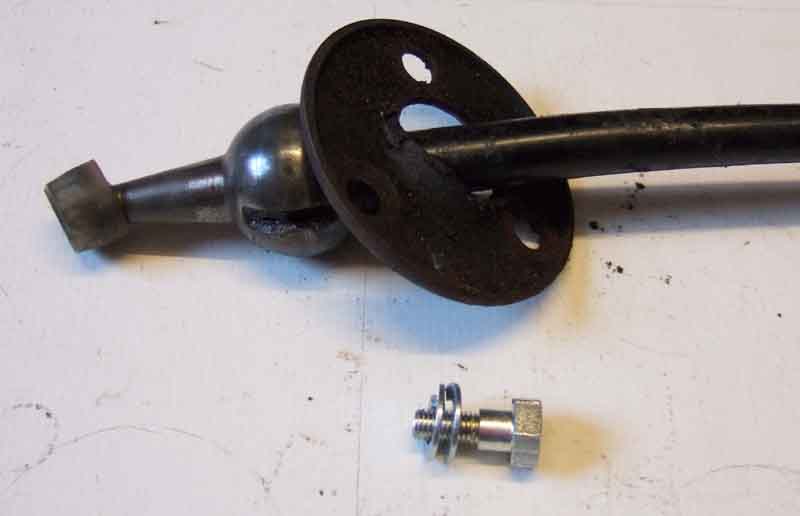
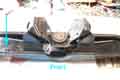
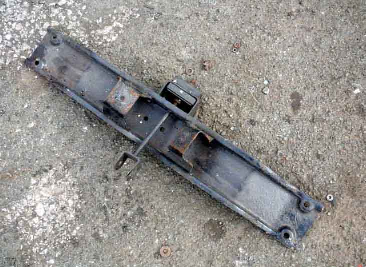 Mk 1 roadsters had a crossmember with welded nuts at the rear for a restraint rod bracket. A short rod passed through the crossmember and brackets and was retained by a nut. The front of the rod has a 'U'-bracket that goes around a protrusion on the bottom of the gearbox casting close below the speedo cable, and a special pin goes through the bracket and protrusion with rubber bushes between them.
Mk 1 GTs and initially all Mk2 cars don't appear to have the restraint rod, until 1974.
 In Feb 74 (still chrome bumper) a new restraint rod was added to North American cars. This used a welded bracket on the front face of the crossmember, and a longer rod going all the way to a bracket that attaches to the two bottom bolts that secure the bell-housing to the engine. Other markets got this arrangement at the start of rubber bumpers.
The V8 never had a restraint rod.
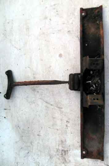
 And in case you wondered what the crossmember bolted up to - a tapped plate in a cage, so it can move around to accommodate some dimensional differences.
For what oil to use see Lubrication.
Take the car for a run of 10 miles or so to warm things up and allow the old oil to run out a little easier, especially the gear oil in the V8. Make sure you can remove the filler/level plug or dipstick before draining the oil. You can live with not changing the oil for a bit while you ponder how to shift it, but not if you have already drained the oil and can't refill it. I had the front of the car up on ramps and the rear on axle stands so I could do both gearbox and rear axle together, and the car was relatively level making refilling with the correct quantity easier.
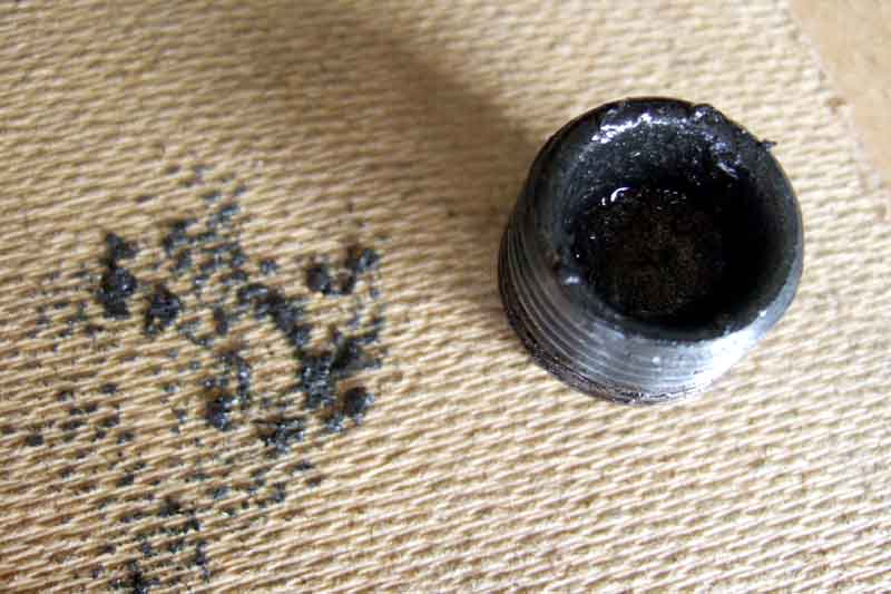 The drain plugs (I did both cars) came undone easy enough, although I found a 3/4" spanner and socket were just a bit too big for the roadster (fine for the V8) so used an 18mm socket instead, and left that to drain while I got on with refilling the diff. The drain plug on both the roadster and V8 are hollowed-out and although at first it didn't look like there were any bits in the hollow, when I stuck a screwdriver in there I did get some bits out. The largest was about 1mm in size, the rest much less than that, I suppose it is inevitable in a manual gearbox but I'd rather not have seen it.
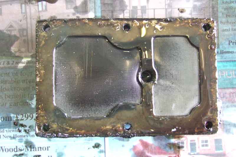 When the dripping had slowed I replaced the drain plug and started on the OD sump/filter. The bolts came undone easily, slackening each bit by bit like head bolts/nuts to avoid the chance of warping. Free the sump with at least two of the bolts on opposite sides or ends still loosely fitted so it doesn't fall away all at once. I had to use a bit of gentle leverage to get the sump parted from the OD body, there is a handy tab on the sump adjacent to the large hex plug for the relief valve expressly for this purpose, it seems. Be ready for more oil to drain out once you have broken the sump seal, quite a bit more comes out here, I left that to drain rather than try getting the sump completely off at that point and fill my sleeves with oil. With the sump off the V8 there was a slight tear in the gasket/filter across the middle bar so I decided to replace it, I had bought one at Stoneleigh last month. The old one took quite a bit of scraping to get off the sump, in hindsight it would probably have been OK to put back as the outer ring was fine. The filter and sump were as clean as a whistle, but got a wash in petrol anyway. The roadster sump came off without any tearing of the gasket, and I decided to leave it stuck to the sump and not clean underneath as any bits should have been on top of the screen. The little specks in this photo are globules of oil or petrol, not bits as I first thought. Touching the screen made some vanish and other appear. I did pour some petrol into the sump through the screen, gave it a good swill and poured it out again, hopefully that should have washed out any fine sludge, it looked clean enough in there from peering through the screen.
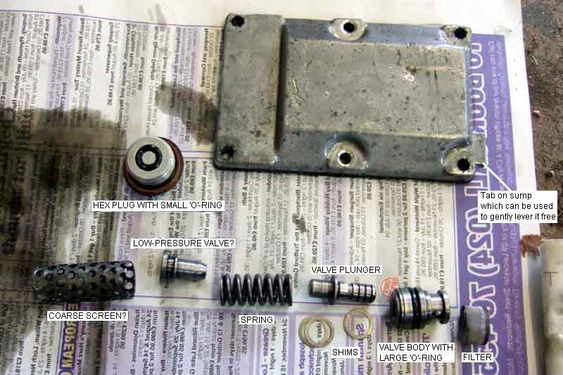 The hex plug for the relief valves also came free easily, a little more oil draining out. Be careful not to lose the little O-ring between it and the valve or any of the other bits inside. Whereas on the roadster it was in a groove in the end of the hex plug and didn't come free in washing, on the V8 as I recall it was loose on top of the hex plug i.e. there was no groove. Careful teasing with a pair of long-nosed pliers got the cylindrical filter out together with the valve assembly. Quite a few bits involved here (13 on the roadster!) so be careful to note what order you find them in - and which way round they are - and not to lose any.
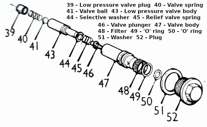 Whereas the V8 was similar to the drawing in the Workshop Manual the roadster seemed a bit different having a very coarse screen round the upper part of the valve which isn't shown in the drawing, and a large spring above the valve plunger which is shown much smaller in the drawing. I didn't find any of the 'valve ball, valve spring or low pressure valve plug' on either car. The larger O-ring should be in the groove in the relief valve body so shouldn't come free. The roadster had three shims between the valve plunger and the spring (not shown in the manuals) which sets the hydraulic pressure - more shims sharpens engagement, less shims softens it, I didn't find any on the V8. I had to replace the filter/gasket as it ripped on removal. The new one didn't leak, but several people replacing them much later said theirs did, it seemed to be coming from the edges of the gasket and might have been from the ends of the mesh wires.
While you are away from the car put a clean empty container under the OD to catch any bits (e.g. the 'valve ball, valve spring and low pressure valve plug' which I didn't find) as they might be there and fall out as the OD cools. If you don't they might roll away or not be noticed on a driveway until too late. Again the filter and valve components were as clean as a whistle, but got rinsed in petrol before replacement in the correct order. On the V8 the new OD sump gasket got a smear of Hermetite Red (non-setting) on both sides, I tightened the sump bolts bit by bit in a logical sequence to avoid warping. I haven't seen a specific torque figure for these bolts, but the standard figure for 1/4" UNC/UNF is 6-7 ft.lb. (8-10 NM) so I wouldn't go above that or you could strip the threads or warp the sump. On the roadster I just put the sump and gasket/filter back as it came off, no Hermetite this time, we shall see if it leaks or not (it didn't).
Level checking and filling:
Chrome bumper 4-cylinder cars have a dipstick on top of the gearbox, rubber bumper and (from Keith Hazell) all V8s have a side filler/level plug. However there is a question-mark over the 4-cylinder 18V836/837 used for 1974 1/2 in North America as the Parts Catalogue indicates the casing did not change until the 18V797 for 1975.
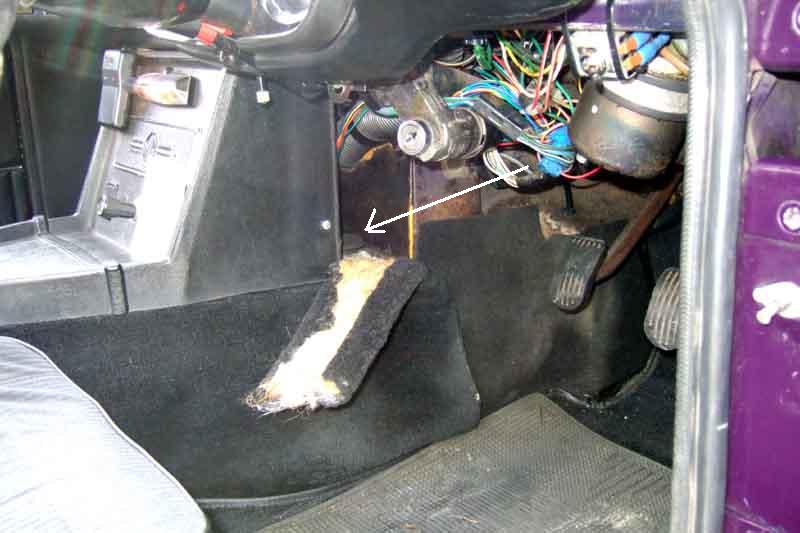 There have been two questions recently about where to find the chrome bumper dipstick and filler, so here they are. Note the access hole and rubber bung were still fitted to rubber bumper cars, and I found that the easiest way to refill the V8 with the side-fill gearbox was with the tubing down through the access hole and into the side-fill hole. However it appears that 77 and later cars had a different console that may have to be pulled towards you i.e. rearwards to access the bung - not a trivial task particularly with the two heater cables. March 2021: Two people have stated on the MGOC forum that theirs do not have the bung, but three others have confirmed that theirs do including a reshell.
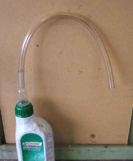 Whilst side-fill is easy to clean around the filler hole and get the end of the tubing into it without picking up any dirt, top-fill needs a bit more care. I loosely inserted the dip-stick to stop any dirt falling in, then from underneath wiped round the dipstick and the top of the casing. OTOH it's easier to get at the CB filler leaning into the cabin than having to raise an RB level to get underneath. I'd seen recommendations to use a long length of plastic tubing up from the filler hole (top or side) into the engine compartment so one can refill in relative comfort, but opted to do the V8 from the right-hand footwell instead. I used a short length of tubing just smaller than the filler hole via the grommet hole in the transmission tunnel (although originally for the dipstick/filler hole on chrome bumper cars it is present on all cars) even though it is a side-fill gearbox. The gear oil for the V8 gearbox comes in 1 litre squeezy bottles and the nozzle of these fitted neatly into the end of the plastic tubing, and I had enough room to empty each bottle in turn even with the steering column on that side of RHD cars. The 4-cylinder uses engine oil in the gearbox and OD, the 1-litre bottles of this don't have the nozzle like the gear and diff oil bottle do, so you will need a funnel in the end of the tubing for either 1-litre bottle or 5-litre can. I also did the roadster from the footwell and rather than try to wield a 5-litre can in the limited space decanted 1 litre at a time into an empty diff oil bottle so I could use the same method as for the V8. Squeeze for a few moments then release and wait a couple of seconds, and the oil in the tube will drain down and air come back up to replace it and expand the bottle again. Much easier than trying to squeeze a litre in all in one go.
 But a Sealey syringe/pump does away with all that faffing about.
It will take time for the oil to flow everywhere so don't pour in the whole of the recommended amount in one go or it will probably overflow. Even though a dry-fill with OD takes 3.4 litres a basic drain and refill will leave almost a pint in the OD etc., and in the roadster I found that after just 2 litres I was having to pull the tube up a little bit to get any air back up the tube into the bottle. Testing with the dip-stick showed it was just above the MIN mark even through there wasn't much more than half the quantity in yet. With the V8 I was able to get about 2.5 litres in without the same effect, for some reason. At this point I ran the engine on both cars in 3rd and 4th (I had the rear of the car raised to do the rear axles as well, remember) switching OD in and out to distribute the oil. While the V8 was fine OD on the roadster wouldn't engage, which concerned me a bit. However when I removed the tube and checked again with the dipstick it was now off the bottom. I put another litre in (making 3 litres so far) and tried again, this time it was OK - phew! MAKE SURE it is supported safely, don't be underneath the car with the engine running, and make sure there is some run-off room in front of the car. Recheck the level and top-off as required, then replace the filler plug/dipstick and check the drain plug is tight before taking it for a run of a few miles. On your return check the level again on a flat and level surface, and check it again when cold after leaving it overnight, rechecking the drain and level/filler plugs are tight. After the next decent run check the level and the plugs again to give you confidence there are no leaks, then you should be fine to leave it the normal service intervals.
Replacement
Checking: September 2016 For a very long time I've suspected Bee's rear oil seal might be leaking slightly, bought a replacement seal, but because drips from the engine were significantly worse there didn't seem much point. After changing Bee's clutch in August and seemingly (so far!) got the engine leak-free I decided to tackle the rear seal. Got underneath to take the prop-shaft off and then remembered that many months ago I decided to see if the seal was actually leaking, by tying a strip of white cloth around the flange shaft adjacent to the seal, and cleaning the bottom of the casing where it angles down and forwards towards the drain plug. The trouble is that not only does oil run downwards, it can also run backwards from air-flow when driving, making it tricky to determine where it is actually coming from. The cloth was perfectly clean, and so was that part of the bottom of the casing, so I'm pretty sure that seal isn't leaking, which means it must be coming from somewhere else. There were drips hanging off the OD filter plate screws, and the drain plug, and I think a little further forwards as well. In the past I've been fairly sure the oil under the gearbox has been clean, i.e. gearbox oil, but moving the car immediately before getting under it did look more like engine oil. As the engine still looks clean - above the sump flange at least - it's a bit of a mystery unless it is the sump gasket, which I didn't touch, but maybe should have replaced when the engine was out. The problem is, where do you stop? Maybe I can tie some longer strips of cloth around the gearbox in an effort to find which section - or sections - it is coming from.
Replacement: by Michael Beswick, August 2013
Having just had my overdrive unit rebuilt, I was rather disappointed to discover it was leaking from the rear oil seal. Rather than pull the entire engine, gearbox and overdrive out again, it was decided in conjunction with the rebuilders that I would replace the rear oil seal in-situ. The most likely cause of a leak is a very slight groove in the drive flange where it runs through the oil seal.
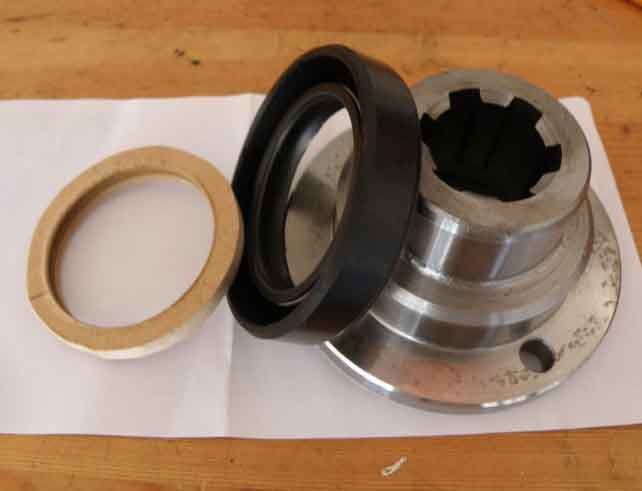 The first photograph shows the new oil seal plus new flange and also a wooden disc I made to help seat the oil seal (in the event I did not use this).
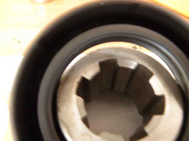 The next shot shows how the oil seal fits the flange.
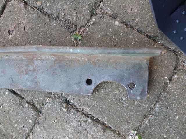 Third shot shows a piece of 2 ˝" angle iron, with a curved section cut out and 2 holes. This is used to prevent the flange rotating thus allowing you to undo the big nut the centre of the shaft (which is 1 1/8 AF, same as the front hub nuts).
First job is to drain the oil. Also be aware that when the oil seal is removed a certain amount of oil will escape. As it took me a while to remove the prop shaft and the central nut on the overdrive there was very little oil left in the gearbox.
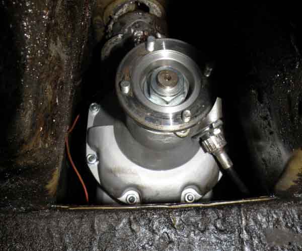 Undoing the nuts on the prop shaft to the overdrive flange requires a ˝" AF open-ended spanner, everything else jams. The bolts are a special type with a flat on them that allows them to fit down the flange and prevents them rotating. Once this is undone you can turn your attention to the flange on the differential. Again it is a half inch open ended and a ring spanner to remove them. I marked the position of the rear flange on the prop shaft and the corresponding position on the flange on the differential. This is probably not necessary as prop shafts are dynamically balanced off-car and should run true with the flanges in any orientation. (As I was removing and replacing the flange in the overdrive there was little point in making similar marks for the front of the prop shaft). The prop shaft can then be fed forwards and downwards and removed.
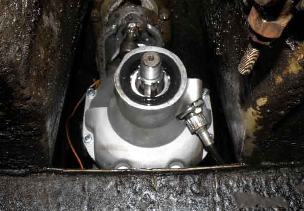 The central nut of the overdrive was pretty tight so I needed to use the piece of angle iron which jammed against the transmission tunnel. Using a 2 foot breaker bar and pulling the angle iron towards me I managed to loosen the nut. The splined flange then simply pulls forwards and off.
(See also this 'universal' tool made from B&Q flat steel strip).
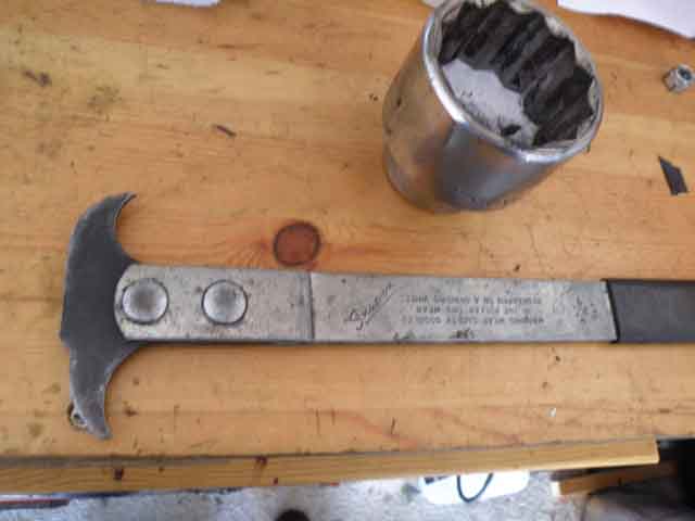 I had been told that the seal could be removed using a screwdriver, but I found that I needed the correct tool. I borrowed one from my local garage but Machine Mart do them for about Ł6. It resembles a small ice pick. It is obvious how to use the pick - set it so there is leverage then a sharp pull will remove the seal. It seems that the tool pulls out the spring that forces the lips of the seal against their respective faces. Thus deformed the seal comes out easily. Care needs to be taken to ensure the tip of the "pick" rests on the seal and does not score the face of the housing-thus producing another oil leak....
Replacing the new oil seal is simply a matter of oiling it all round and then using a large socket (or equivalent drift), and tapping it home ensure it is square. I then used a soft-faced mallet to ensure the seal was flush all the way round.
The special prop-shaft bolts have to be fitted to the drive flange before the flange is fitted to the gearbox or OD. It is worth cleaning up the threads on the bolts with a die. Trying to get the nut on a semi-captive bolt is a fiddle, as the yokes of the U/J get in the way.
Oil the lip of the seal and the flange, replace the splined flange, and fit the washer and nut. The large central nut needs to be tightened to 55 foot pounds and I discovered by putting the car in second gear that I was able to achieve this. It may well be that using bottom gear would be sufficient to enable this nut to be undone and therefore the piece of angle iron would not be necessary.
Slide the prop in from the gearbox end and reconnect the diff flange and the o/d flange. The diff is relatively easy, but the o/d one is a fiddle (again!).
Replace the drain plug and refill with oil.
I could have refilled with oil before attaching the prop-shaft, then started the engine, engaged 3rd or 4th and overdrive which would have served two purposes - firstly it would have allowed me to top-up and correct the oil level there and then as it always drops a significant amount the first time the gearbox is run and OD engaged, and also to see if the new seal leaked. However I only thought this after I finished reconnecting the prop.
Now what? Spoke to Geartech where I had taken the gearbox and OD who said they don't do classics any more and had farmed it out to Klassik Transmissions in Wolverhampton. Spoke to Klassik who muttered something about it being done as a trade job (so?) and that they had stopped doing MGB boxes a couple of years ago as so much had gone NLA and what was still available was poor quality - i.e. situation normal in the MGB world! But if I took it in they would 'have a look at it'.
So Vee is stuck in the garage pending thoughts on what to do next. Do I want to pay for another refurb if it's only going to last that long? Do I want to put the same amount of effort as I did last time or farm it out for removal and repair? And dare I risk that after the nightmare of the body paint and engine rebuild? Or do I want to pay around Ł5k for a five-speed conversion? I make my decision.
August 2024: I bring the old gearbox back together with all the ancillaries - in the back of Vee! - and being an inveterate fiddler decide to take the side cover off. Given the symptoms I felt the gear sets must be moving on the mainshaft i.e. end-float. 3rd gear pushing the synchroniser assembly back on the overrun which pushes the selector fork back and hence the gear-lever. 2nd gear rubbing on something it shouldn't indicated the same. The WSM shows end-float between 2nd and 3rd gears being checked with a feeler gauge and the spec is 3-8 thou, but this is what I found:
Masses of end-float between 1st and 2nd and 2nd and 3rd? It's not wear over time as I got on the motorway with both gears working normally then 80 miles later came off with this problem in both gears. It didn't get any worse over the 130 miles or so back home, nor in 35-mile trips back and fore to Vitesse in Hinckley. There should be two thrust washers on the mainshaft in those positions, it's as if one of them has broken up and come off. Vitesse drained it so small pieces may have come out then, I'd have expected some large bits to remain behind but I couldn't see anything. Roger Parker concurs saying the end-float looks like a goods train being shunted about! He has seen similar when a thrust washer broke up but has always found bits inside. He suspects, as do I, that a non-metallic substitute was used that has been completely mashed by the gears hence no bits.
So in October I decide to launch into a full dismantle. I have the Leyland WSM (assumes the availability of many special tools), Haynes (more practical for the home mechanic), plus this description of a dismantle and reassemble of a non-OD box by a DIY-er purely for interest, and read them repeatedly. Manuals tend to flip about between sections so I scanned both those, edited down to the bits I wanted, then reassembled them into the correct sequence and printed them out. 1st-motion shaft is removed first in the manuals but not easy as the only access to the bearing outer is through the side access with lots of sensitive bits round it. Selector shafts and main-shaft took quite a bit of drifting, with those out the 1st-motion shaft was easier going straight through the middle of the gearbox (not needed as it turned out), and half an afternoon saw them all out.
 I could immediately see what was wrong - the (reused at least once if not twice) lock washer had not been staked down into any of the three recesses in the mainshaft nut and it was coming unscrewed! That was allowing the gears and selectors to move up and down the main-shaft. All that stress, effort and Ł5k for a replacement gearbox because of a Ł3 lock-washer. Talk about 'For want of a nail ...'.
Not only that but I could also see some nibbling in the 2nd gear selector/synchroniser assembly, so because the gears were moving down the main-shaft the selector had moved far enough to come into contact with the edge of the 2nd gear part of the laygear:

 I'd already been looking for the thrust washer 22H276 as initially I had felt that would be the culprit but it was NLA. So now I started looking for the lock-washer 22H773 and that was the same as far as eBay and all the usual suspects went. It's basically a flat washer with two tabs that lock into the main-shaft then you tap the flat part into three angled recesses on the circular nut. Dimensions are fairly critical as it has to be at least the same diameter as the nut but not much wider as the 3/4 selector hub has to be able to pass over them. I reckoned I could make one at a pinch given a flat washer of about 1/5" OD and 1" OD, cutting two tabs at 180 degrees, then clamping it in a nut and bolt in a drill and grinding down the excess diameter. Googling nothing of that size same up, but one with a large enough OD but a smaller ID could be opened up. Then on the advice of Roger Parker as a last resort (based on past experience ...) I tried emailing MGB Hive and they had two in stock! I left the other one for somebody else. Not only that but when it arrived it was the correct part (which hasn't always been the case ...)!
 Being flat against a flat face on the shaft the staking is difficult to get started, really it needs a sharp edge something like a wood-chisel. But I managed to get it into all three recesses in the nut.
Then reassembly, which needed a bit of thought as there are a couple of approaches each with their own pros and cons. Although the shafts went in easier than they came out it took three further part afternoons with new gaskets and oil seal for the 1st-motion shaft, testing each stage of the assembly to make sure everything worked as it should.
All hunky-dory now, with gears being selected without the gears themselves moving up and down the shaft!:
 Although selecting the correct (4th) gear made inserting the interlock assembly arm a doddle, it also meant that things were moving around all over the place when trying to fit the remote extension to the gearbox, which kept dislodging the interlock. Selecting 1st gear (manually) solved that, and it's ready for the OD to be refitted depending on whether I sell them separately or together.
The obvious thing would be to keep it with the car as the next owner might want to reinstall it, but to be honest by the time I come to sell it I don't think I will be bothered about getting a bit more money for the car on that basis, I'd rather move it on now, get a bit back against the cost of the 5-speed, and get back the space in the garage. The same goes for the prop-shaft (which I can't use on the roadster without changing the OD drive flange) and cross-member assembly (which I could but how likely is that?).
November 2024:
 Advertised it on the V8 Register and a week later had an enquiry, chap wanting to put an LT77 conversion back to 4-speed OD so wanted the whole installation from clutch to propshaft and cross-member. He'd only had the car as a project for about a week and just started looking for a gearbox, so fortuitous for us both. Wanted the OD as well so I put that back on, and he picked it all up about a week later.
Nice to see someone putting one back to original, maybe someone will do that with Vee one day.