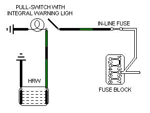
Chrome Bumper to 1970
Hover over a wire to confirm the colour
Note 2: There was a separate wire from the front to the back of the car for the HRW, and on at least one example this feeds the left-hand side of the screen instead of the right-hand side on later cars. Also being optional the earth wire route and connection could be anywhere.
Chrome bumper 1972 model on and all V8s
Rubber bumper to 1976 (not V8)
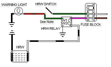
Rubber bumper 1977-on
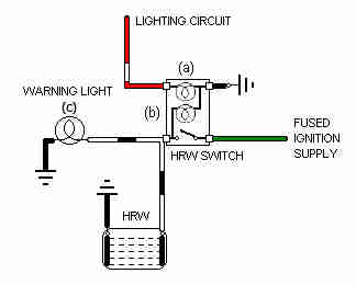
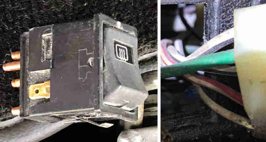
Albert Ross show this wiring on the connector to his 1980 HRW switch, which is rather confusing. There seems to be a green (12v, correct), three white/blacks (there would only be one to the HRW, plus one to an external tell-tale which he doesn't have), and a red/white for night-time illumination which would normally go to one of the spades on the side of the switch, plus a black (earth for night-time illumination to a spade on the other side of the switch) which isn't shown:
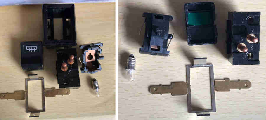
His switch, showing multiple pins instead of just two pins which is how replacement switches for the MGB are shown:
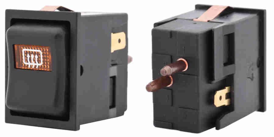
As the original switch part number is unknown this 1977 and later Mini switch YUF101680 might be suitable, although it has a yellow lens on the rocker instead of probably a green, and the edges of the rocker look more rounded. It still has the two spades on the side for the red/white and black wires, but has only two pins on the back for green and white/black wires (which is all it needs ...): (Moss Europe)
But information from owners is confusing in that cars earlier than 1980 only have the night-time illumination, but a 1980 has the tell-tale but not night-time illumination! Whether that is because of a failed bulb, or a faulty connection somewhere, wasn't established. More info on internal bulbs here.
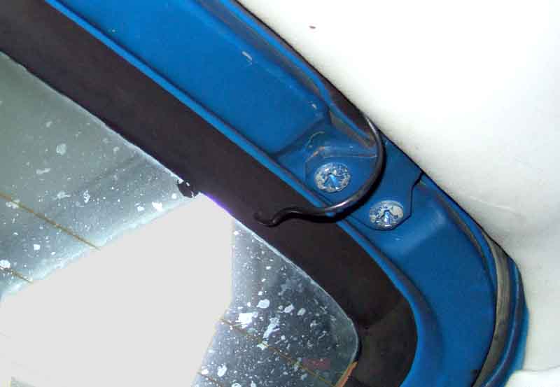
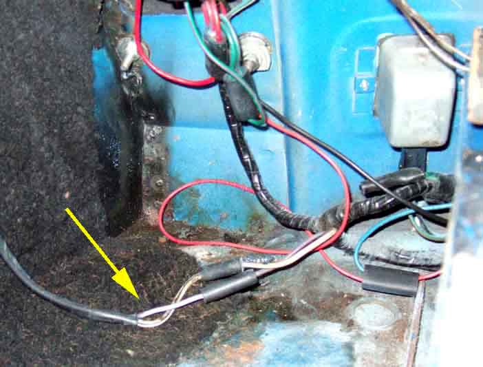
Hatch closed, just a small loop of wire visible
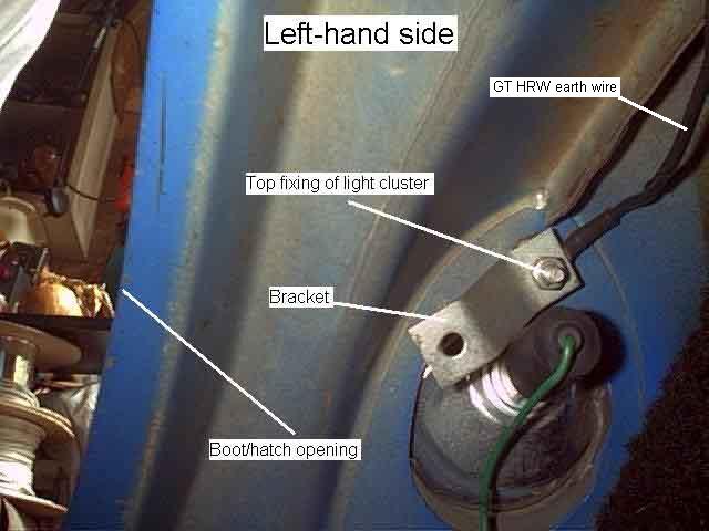
This is the earth wire which runs down the C-pillar to the top mounting stud of the rear light cluster. A similar wire runs down the other side to join with the rear harness by the light cluster. (The bracket is for the carpet piece that covers the back of the light cluster.)
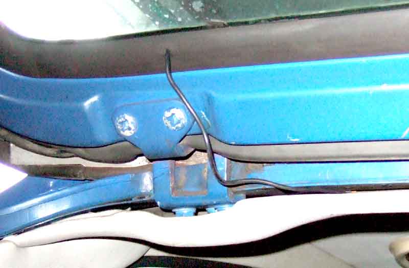
The two 12v feeds going up the right-hand C-post for the HRW (white/black) and the load-space light (purple).
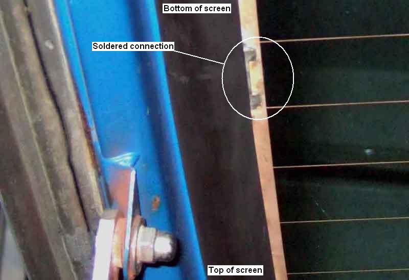
The soldered connection point on the surface-printed element, about mid-way down the side of the glass, with the connections and wiring covered by the rubber seal, but exposing a test-point.
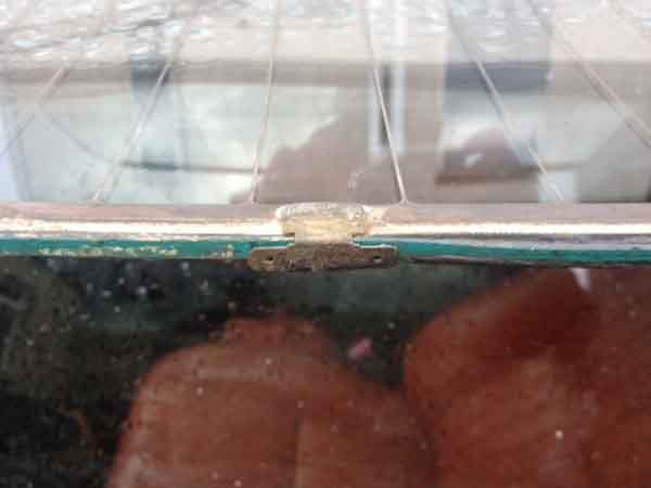
Robert Kerr's car, glass removed, showing the two spades on the inner edge of the glass. I'd say extreme care needs to be taken if you need to disconnect/reconnect the wire attached to this connector, say when replacing the glass, to avoid the risk of detaching the connector from the screen.
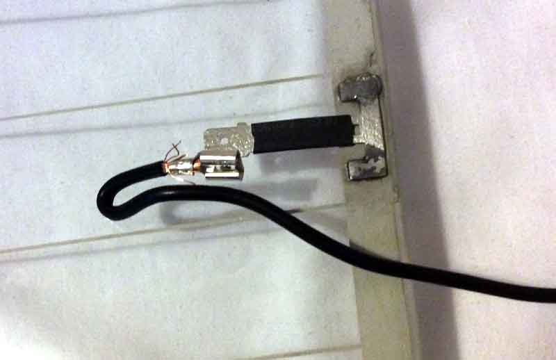
Roy Marshall's replacement glass, showing the very inconvenient connection arrangements.
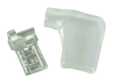
I suggest a right-angle wiring connector is the best way to get a half-way neat installation, however check the size of the spade on your glass first.
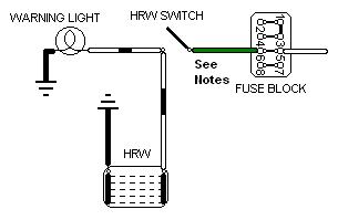
Note 2: In some diagrams the wire to the external warning light is shown as red with a brown stripe off the same terminal as the white/black to the screen.
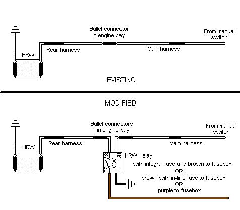
Note 3: The 12v circuit from the switch has bullet connections where the main harness joins the rear harness in the engine compartment, by the right rear light cluster where white/black for the HRW goes up the C-pillar (together with purple for the load space light); and where the white/black connects to the wire coming out of the screen rubber by the right-hand hinge.
Note 4: The earth circuit uses a single black wire down from the bullet connector by the left-hand hinge, to the top mounting point for the left rear light cluster.
Note 2: The 12v and earth connections are the same as for the 1971 and later, see Notes 3 and 4 here.