
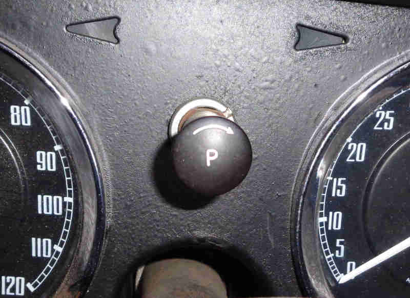
Still above the steering column the logo changed to a representation of what looks like a speedometer on North American Mk2 cars and V8s, and late CB/RB cars for other markets - 37H7995 (the badge marks the visit of the Canadian Lancaster to the UK in 2014, we saw her flying on a number of occasions including her arrival at Coningsby in very marginal weather):
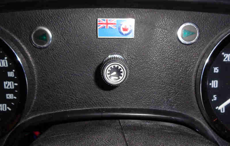
On 1977 and later RHD cars the rheostat moved to below the speedometer:

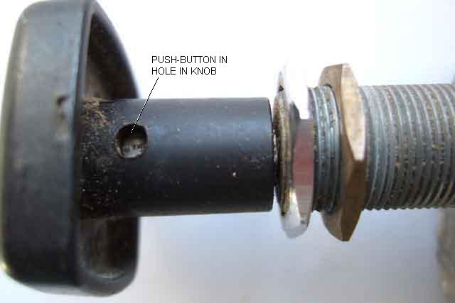
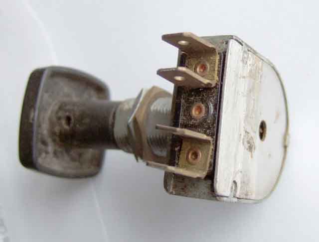
Showing the recessed push-button in the rheostat knob (this square one is not from an MGB), and also the two nuts on the threaded portion of the rheostat body. The brass nut is there for aesthetic reasons to space the rheostat back from the panel so that the outer nut ends up flush with the end of the threaded section, and doesn't leave exposed threads:
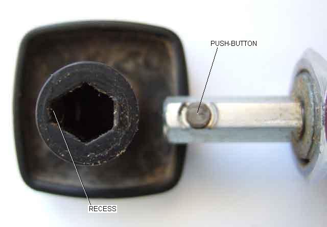
Showing the push-button in the shaft, and the recessed face of the hexagon in the knob which must go over the push-button when refitting:
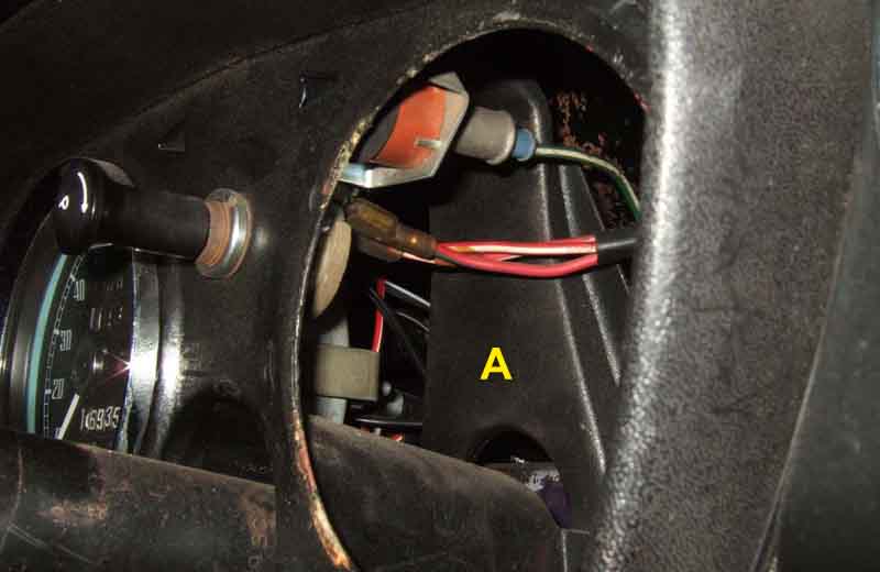
The CB (except V8) bracing panel 'A' behind the rheostat and between the two main dials which prevents access to the back of the rheostat directly. The column switch cowl may also need to be removed to be able to withdraw the tach depending on the vertical positioning of the column. You may be able to reach the connections like this, but having got this far two more steps to remove the knob and rheostat locking ring and you should be able to get it out through the tach hole:
V8 and RB without the bracing panel, which together with the smaller main dials gives better access:
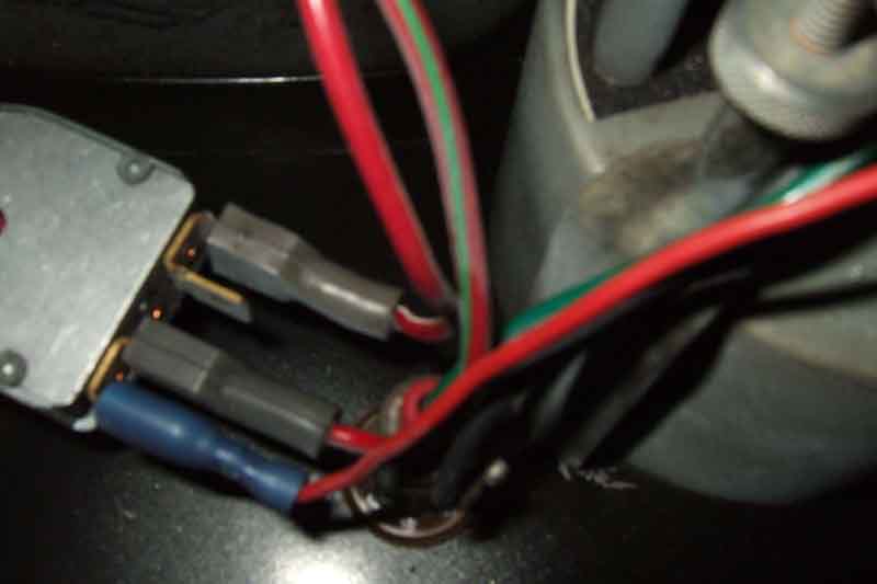
Just by removing the knob, locking ring and wavy washer you should be able to withdraw it from the dash and bring it down far enough to access the connections:
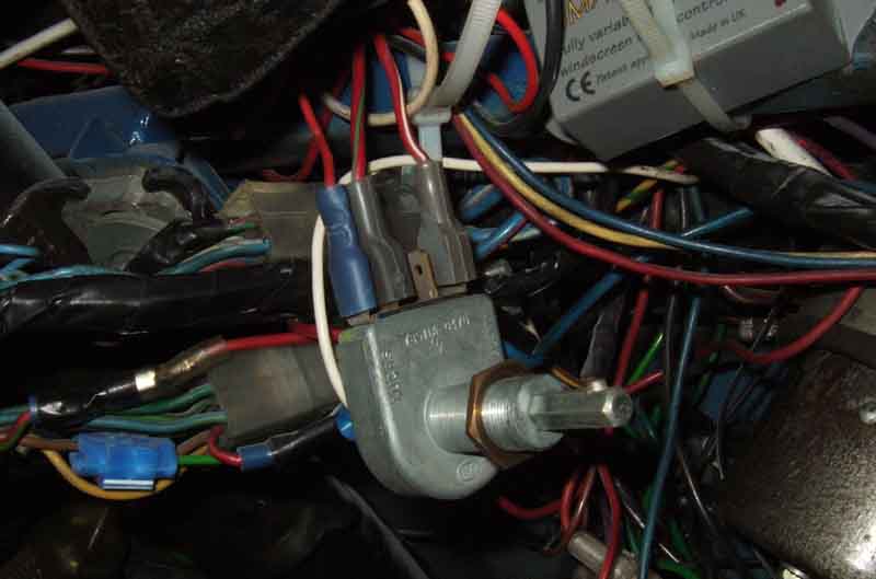
The 77 and later rheostat is heavily shrouded by the dashboard:

I strongly suspect that this dashboard was installed with all the electrical components (at least) already fitted as it has its own sub-harness that plugs into the main harness. For that reason the recommendations in various manuals to remove or pull forward the dashboard is perhaps not that difficult, but it would still need to be pulled forwards far enough to get behind that shrouding. The speedo cable may be the limiting factor in that, unless disconnected from the overdrive first. If you could remove the speedo from the dash (later cables were long enough to allow the cable to be disconnected from in front of the dash) that would make access to the rheostat easy, but the speedo itself is also shrouded. The best option may well be removal of the right-hand air-vent as that is the method used to access the dual gauge on earlier cars, maybe to remove the oil-pressure gauge but there may be enough room to fiddle the rheostat out to drop below the dash as above without that.
However Dave Birkby managed to get it out without any of that using the above picture to see what he was faced with, dropping it below the dash. It was seized (in a GT) so he wanted at the very least to be able to turn the panel lights off, and like me doesn't like things that don't work. Once out he clamped the spindle in a vice and with a bit of WD540, contact cleaner and gentle persuasion got it moving again with it's full range of resistance including 'off'. Getting it back in was the biggest challenge, one of the problems being a wire wrapped round the spindle preventing it from fully seating. But after four attemps he was successful - at the expense of his left hand looking like it had been in a paper shredder!
General view of a printed-circuit rheostat (from a previous car) showing the two spades for each terminal in a 'U' shape:
Internal view of the rheostat showing multiple printed circuit tracks of varying thickness and length. The lowest wiper 'A' is feeding input current to the inner ring of the tracks (the direction of current flow is not important I just use 'input' and 'output' for clarity). The upper wiper 'B' - shown near the minimum brightness position - is the output and runs across a series of pads with tracks that loop to the adjacent pads, going back to the input ring. Each loop has a different length and resistance of track, the upper pads with long, thin tracks of relatively high resistance at the 'dim' end, getting shorter and thicker i.e. less resistance as you go round in an anti-clockwise direction brightening the lamps, to end at the wide pad bottom right. At the minimum end all the tracks are in series with each other, and when the upper wiper is on that wider pad the rheostat is effectively bypassed and the lamps are at full brightness. There is an 'empty' pad just the right of wiper 'B' i.e. no tracks, and in this position the panel lights are off altogether i.e. at the 'dim' end (some rheostats have the 'off' position at the bright end):
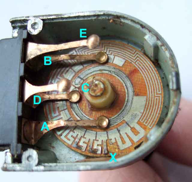
When the variable section suffers heat damage it's usually at the brighter end as has happened here at 'X' with one section burnt out altogether and two others damaged. The 'bright' end is where current and heat are at their highest and being concentrated in a short piece of track is what does the damage. The effect of a break here is usually that the rheostat does vary brightness, but even at it's brightest it is not as bright as it should be. This means it's not obvious that it is faulty, unless you bypass it:
The short wiper in the middle 'D' feeds input current to another section of track on the back cover, and 'E' feeds that current direct to the output terminal.
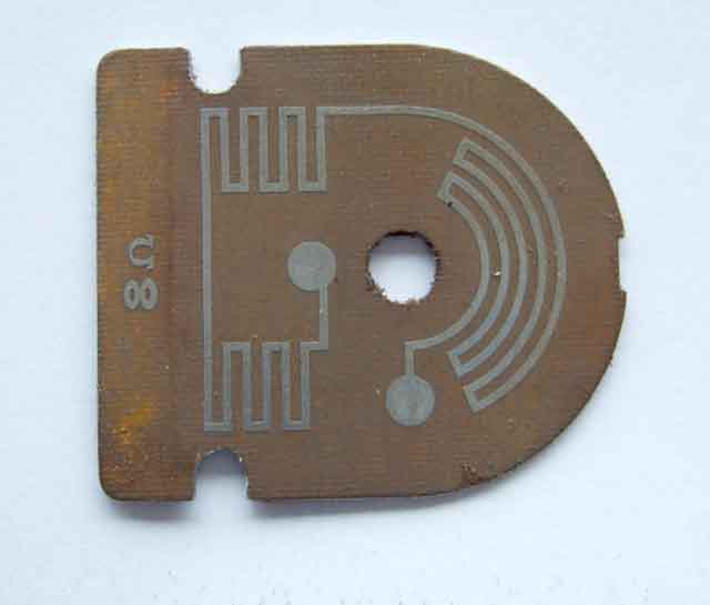
View of the rheostat back cover showing another track and the inscription '8 ohms'. This is a fixed resistance and is in parallel with the variable section (feeding input current from 'D' direct to the output terminal 'E'), which means that the rheostat varies between 0 ohms and 8 ohms:
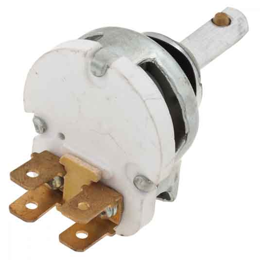
All mine (two MGBs, two non-MGB all failed when they came to me) have been the above printed-circuit type but most people say theirs are wire-wound as here which have a completely different appearance. Less susceptible to burning out, may suffer from a poor connection between the wiper and the winding, but can be cleaned. The base on these is insulated either white ceramic as here or blue plastic, with visible windings through the ventilation slots, and the spade pairs are rotated through 90 degrees. This type are usually stiffer to rotate, and have a 'scratchy' sound and feel compared to the printed-circuit type:
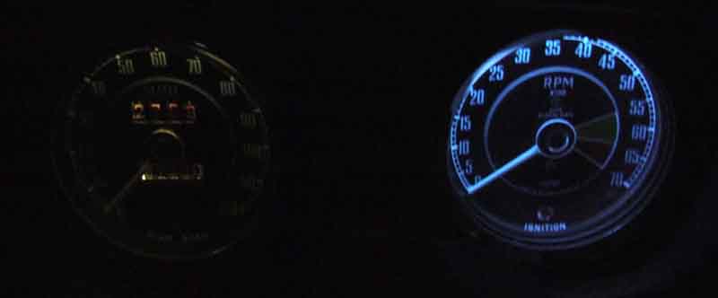
Inside of a fuel gauge case showing the 'duck-egg blue' paint, which tends to make the yellow light from a low-wattage incandescent bulb whiter:
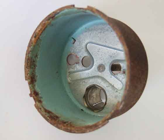
Using bright white LEDs can result in a bluish tinge to the light, which I don't find unpleasant. More info on LEDs here:
Showing the back of the fuel gauge face-plate relative to the case which has the same blue colour on the back of the upper part (carrying the 'SMITHS' and 'FUEL' markings) but matt white on the back of the main part, the lower half of which carries the graduations. The bulb is situated at the bottom of the case and so mainly illuminates the white area of the face plate and the inside of the case. Light scatter then has to occur to get through the aperture at the top of the face-plate, which then has to scatter still further before it reaches the pointer and graduations:
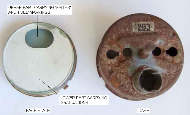
This is probably why the fuel gauge is the dimmest, even with various types of LEDs. I did manage to improve it greatly by modifying the innards - on an old gauge as an experiment - but not worth the effort and risk of damage on the ones in the cars