
Screwed type
Locking ring type
76-on
'Plastic' senders
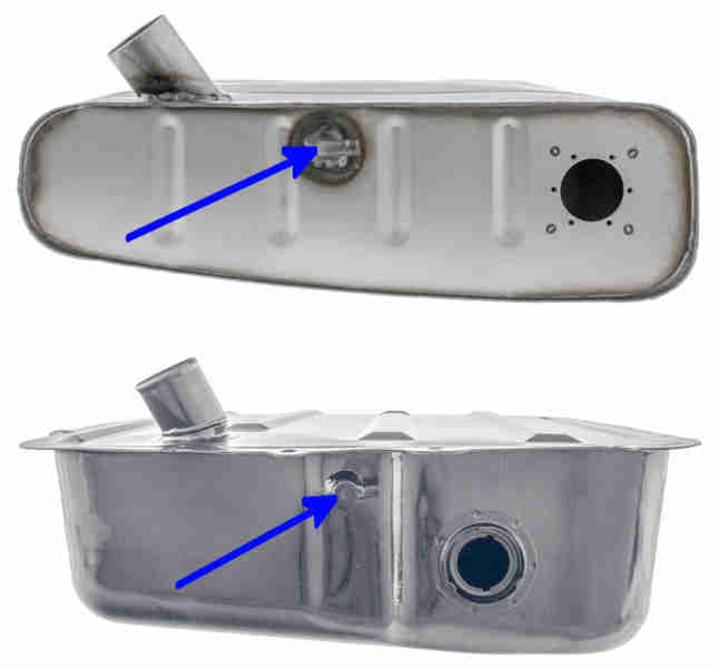
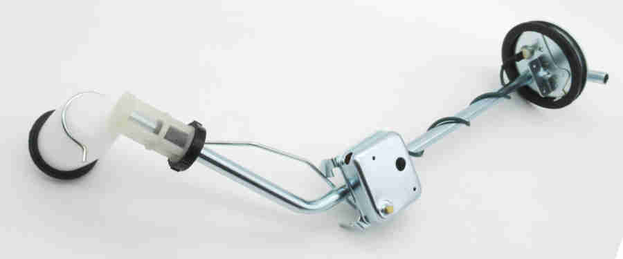
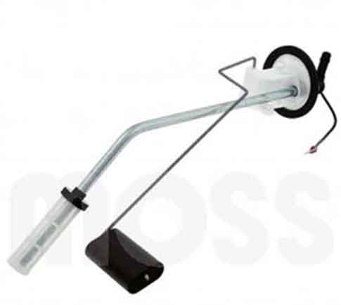
Relative positions of the screwed sender on the original strapped tank and the locking-ring sender on the later bolted tank, fuel outlet positions indicated (prior to 1977): (Moss Europe)
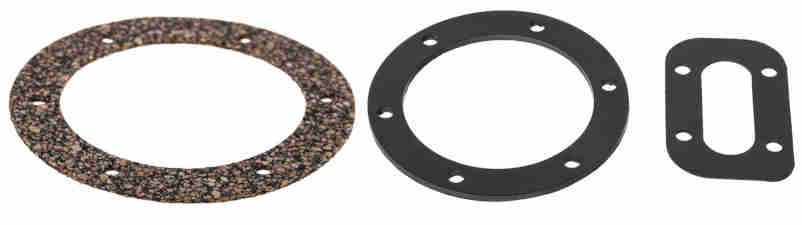
Original cork gasket on the left, more recent Viton alternative 'for all fuels' (at five-times the price) plus a gasket for the cover: (Moss Europe)
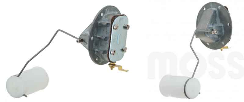
Screw-fitted sender for the early Smiths thermal gauge used from October 1964 for the remainder of Mk1 production, this seems to have the 'flat' outer face like the later senders. Long NLA a re-manufactured item from two sources - jmccspares in the UK and Bastuck in Germany. Note this version of sender was used from October 1964 to March 1965, not from 1962 as indicated on the suppliers web sites, however if you have to replace the original Jaeger gauge with 17H 299 new stock of which are bi-metal and not magnetic you will need this sender as well as a voltage stabiliser:
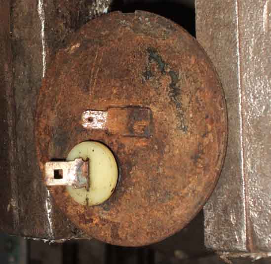
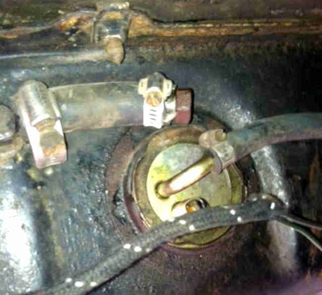
December 2022: Geoff on the MGOC forum posted this picture of the sender on a 1964 car. As a 64 it could have had either system from the factory, but his chassis number predates the change by several months. This sender could well be the same Smiths one as above, but what looks like a 2-wire connector going into the sender and the wiring mods means it could be from something else altogether. His car has had the fuel gauge replaced by a voltmeter and he was enquiring about putting one back. He bought a Smiths gauge (an original Jaeger gauge on eBay was over £200) and stabiliser but it didn't show anything with about half a tank and testing indicates the sender is faulty:
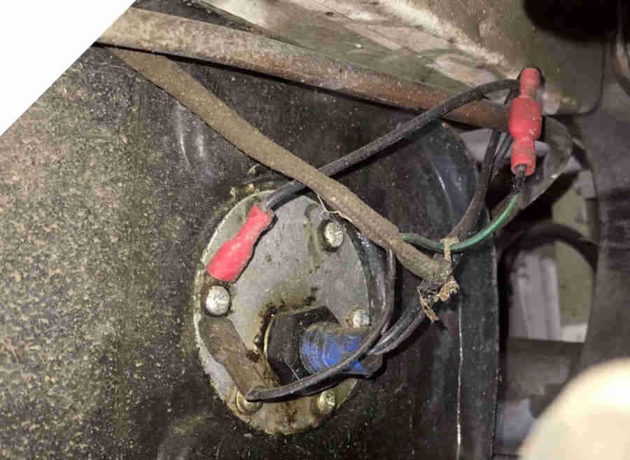
It may well be that the PO fitted the 'wrong' sender and when the fuel gauge didn't work, that didn't work either so they gave up on it. This complicates things as you need to know what type of sender it is, as well as whether it works or not, to know which gauge is needed. There is also the stabiliser to consider - if the Smiths system and that is missing as well then the polarity of the car needs to be taken into account as replacements are electronic and polarity sensitive.
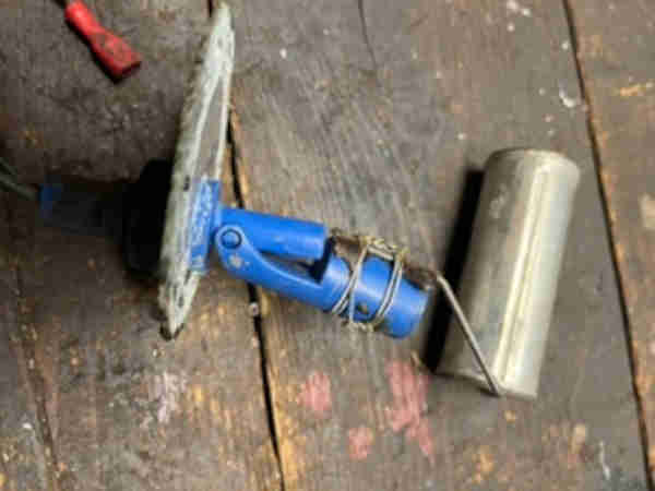
Geoff replaced it with the remanufactured interim type above and as well as the existing sender being completely different externally it is even more different internally! It looks like it could be a magnetic proximity system. There are float switches similar to this but they open and close a contact which isn't much use for fuel gauge, so would have to be part of a tuned oscillator circuit, needing a whole mess of electronics at the gauge end. I can't make up my mind whether it is a home-brew experiment or from a very different marque and model, although perhaps a bit too much of a lash-up for the latter:
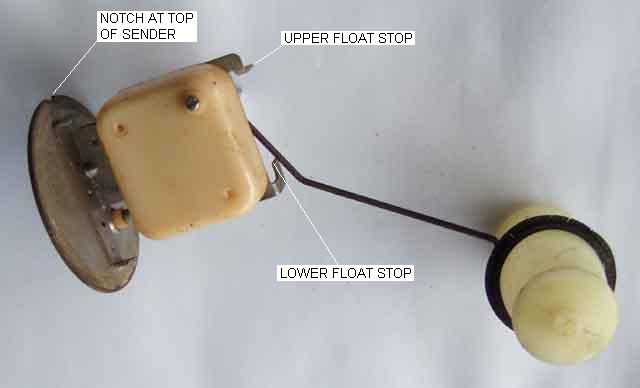
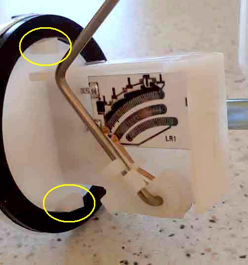
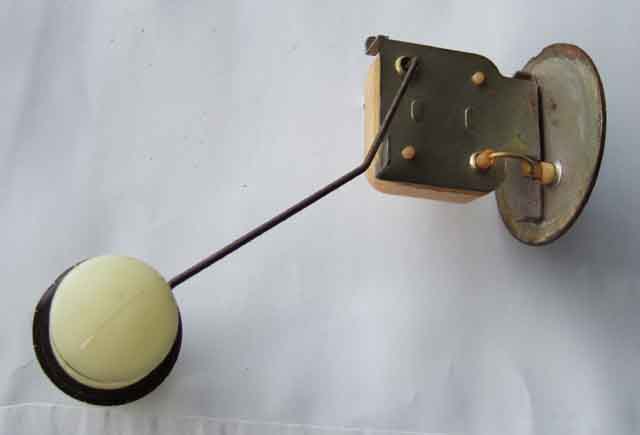
Float shown in the 'empty' position showing the upper and lower 'stops' for float arm movement. The screwdriver slot isn't for calibration as one may hope but is just cut into the end of the float arm where it comes through the plastic box which is one half of what locates the arm. The tabs of the upper and lower 'stops' do give some adjustment of the upper and lower extremities of movement of the float but they are designed to set the relative positions of the wiper to the ends of the resistance winding at the upper and lower extremities. You may be able to get a bit more travel of the float by adjusting these but go too far and you will allow the wiper to come off the end of the resistance winding which will cause the gauge to drop back past E. You can also bend the float arm up and down which will alter the relationship between fuel level and wiper position and hence gauge reading but unless you get it right first time is much more of a fiddle to calibrate the gauge than adjusting the gauge itself. As new senders seem to stop short of both E and F bending the float arm will result in being even more short of F if you adjust for E or vice-versa. Note also the notch at the top of the sender mounting plate, however this is not the main part that ensures correct orientation in the tank:
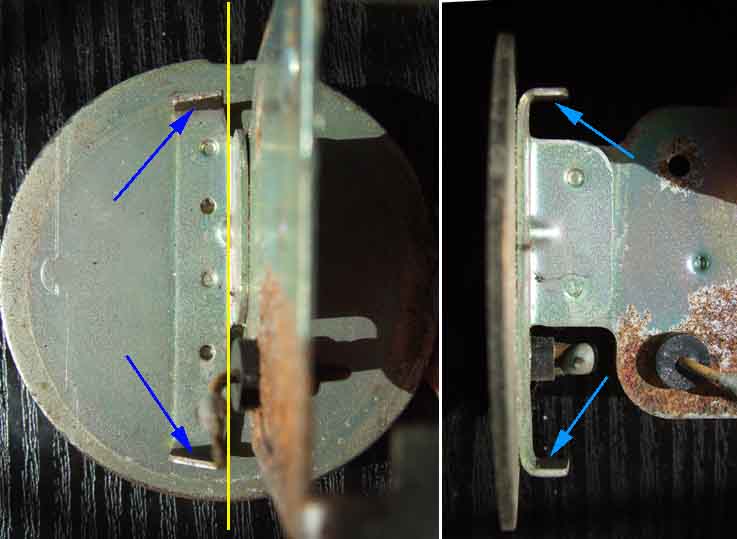
That is done by two offset tabs on the inside face of the mounting plate - seen here to the left of the yellow centre line, that engage in cut-outs in the tank:
Similar offset tabs on the later plastic senders: (Mark Morris)
Matching offset cut-outs in the tank:

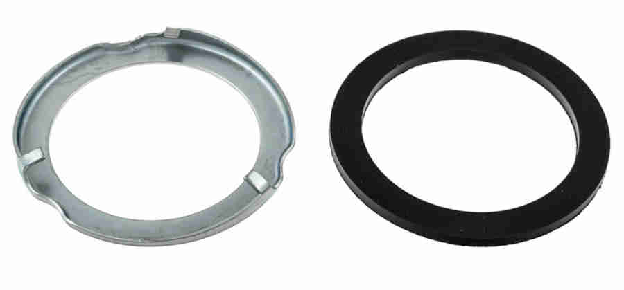
Locking ring and rubber gasket for the later system. Note that the gasket goes between tank and sender not between sender and locking ring: (Moss Europe)
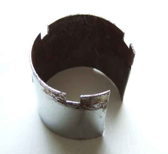
Three tapered sections (A) on the ring slot under turned-over lugs (B) on the tank. Originally Service Tool 18G1001 would have been used, but in the absence of that I've always done it by going round the three tabs (C) on the ring in turn bit by bit tapping carefully, turning the ring anti-clockwise to remove and clockwise to replace. If there is petrol in the vicinity you should be careful not to make a spark, perhaps by using non-ferrous tools, but you shouldn't be striking it that hard anyway. When removing turn the ring anti-clockwise far enough to align the three recesses in the ring (D) with lugs 'B' so the ring can be completely removed, reverse for refitting. When tightening tabs 'C' should stop short of lugs 'B'. All three tapered sections should be locked under their respective lugs or the sender will not seal:
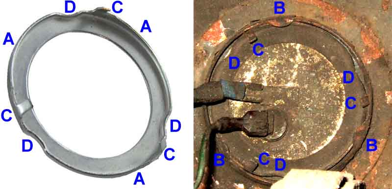
If the three tabs 'C' have been sheared off (as happened to Mark Morris) you will have to try something else. One possibility is to carefully drill through the locking ring in at least two of the recesses 'D' and use self-tappers with the points ground down once the thread has been started. If you leave the points on they could dig into the tank part of the fitting and you will be no better off.
Locking ring removal tool 18G1001. On the basis of that not difficult to fabricate one. I'm not sure why it needs a cut-out, much less an L-shaped one, surely one would disconnect the wires before undoing the locking ring?
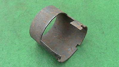
A couple of hours - first looking for something about the right size (plastic cap of aerosol contact adhesive) to act as a pattern, then for a suitable bit of metal (an off-cut from an exhaust trim that's been in a box of metal bits for years). Longitudinal cut so I can open it out to the right size (about 6cm), then three slots at 120 degree spacing (about 5mm square), and Bob's my uncle. Haven't used it anger as I don't want to break the seal until I need to. May need a couple of holes drilled through the outer end for a tommy-bar. I don't think that end will need welding up like the above as it's pretty hard metal and needed quite a bit of effort with two pairs of pliers to open up:
Showing the standard spade in an insulator for the green/black gauge wire, and the under-sized earth wire spade riveted directly to the base:
The other side again with the float shown in the 'empty' position showing the float arm going through the metal back-plate and the end of the resistance winding coming out through an insulated plug and going to the back of the insulated spade terminal. Note the rubber ring on the float which in theory is to prevent the float rattling on the bottom of the tank with low fuel levels. However in practice the lower float arm stop further downward movement of the float quite some time before it reaches the bottom of the tank. On my cars this happens with somewhere between a half gallon and a gallon before they actually 'run out' i.e. the fuel level drops below the level of the pickup:
With the float relatively close to the side of the tank you get the gauge rising on a left-hand bend and falling on a right-hand, which then takes several seconds to stabilise after straightening up. Some have said they prefer the earlier 'undamped' system as the gauge goes back to the actual reading quicker.
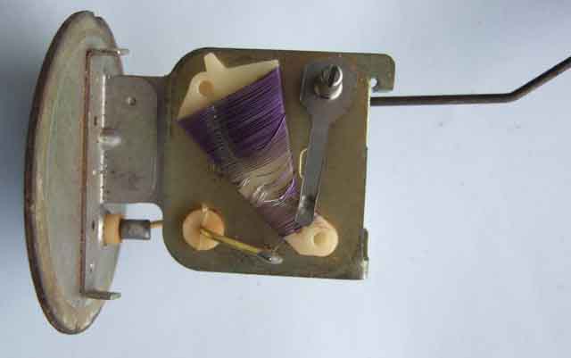
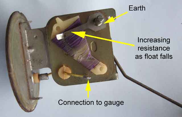
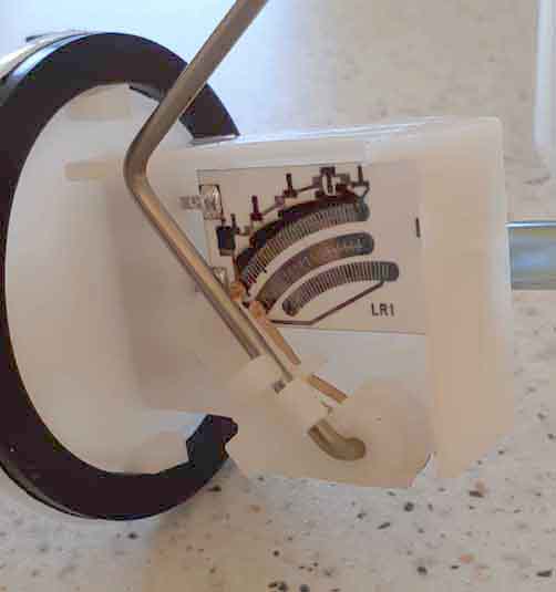
Inside the plastic box, float in the upper or 'full' position. You can see the wiper attached to the float arm and the resistance wire wrapped around the former. Where the float arm comes through the metal back-plate it picks up an earth connection which it then applies to the resistance winding by the moving wiper. The resistance winding has a connection from its lower ('full' or low resistance) end to a stiff wire which goes through an insulator in the back-plate to the insulated spade connection on the sender. This means that when the tank is full there is very little resistance in circuit, a relatively high current flows, and the fuel gauge reads full. As the level in the tank falls, the resistance increases, the current falls, and the gauge reading reduces. Clearly visible is the damage to the windings probably caused by a poorly manufactured or adjusted wiper. This is the 'original' (or at least very old) unit off the roadster, but the 'original' and the first replacements to both roadster and V8 all failed in exactly the same way. The second replacements to both cars have (so far!) lasted much longer:
Float shown in the 'empty' position. All of the resistance is now in circuit from the earth on the wiper to the terminal leading to the gauge, so minimal current, and minimal gauge reading. In both pictures you can clearly see the change in shape of the winding former about 1/3rd the way from F to E. The narrower width at the F end means the turns are shorter, so there is a relatively small change in resistance as the float starts to fall from F. When the former starts widening, the turns are getting longer, so the rate of change of resistance gets higher as the float falls further. Then there is a change from wide-spaced turns to close-spaced turns about half-way up this widening section, about 2/3rds the way from F to E. This increased number of turns also causes the resistance to increase rapidly as the float moves down, doubly so with the increasing length of the turns. The reason for these two changes in the rate at which the resistance increases as the fuel level drops, is partly because of the natural non-linearity of the thermal gauge and partly because the float moves in an arc, and is an attempt to compensate for those. However it's only partially successful. It's quite normal to see a slow fall from F to 1/2, then shortly after that it seems to drop like a stone towards 1/4, then thankfully slow again after that. Whether the modern 'solid state' senders are any different isn't known. Potentially (ho ho) they could be as the wiper passes over a series of contacts with resistances wired between them. Even to maintain the existing 'linearity' the resistance between each contact would have to vary in the same way that the winding resistance varies, so in theory they could have varied them in such a way as to give a linear movement at the gauge, but whether they did or not is another matter:
Voltages and resistances needed to drive the gauge: I had to use 12v as the supply voltage as I have the original thermal stabiliser which switches 12v on and off to average 10v and not an aftermarket electronic that outputs a steady 10v, I used various values of fixed resistance to position the gauge pointer on the level marks. Note the voltage is linear but the resistance isn't, almost certainly due to the positive temperature coefficient of the resistance wire inside the gauge, combined with the changing force needed to bend the bi-metal strip at different points along its movement. Also note that my voltage to show E is higher than normal as I've chosen to have about a gallon left at that point. But whilst the gauge clearly has factory (Smiths, not MG) calibration marks at E, half and F, at the end of the day it's what your sender characteristics are that determines what your gauge will show, and I have found three replacement senders out of four needed the gauge to be recalibrated, the first replacement for Vee showing significantly above E when I ran out:
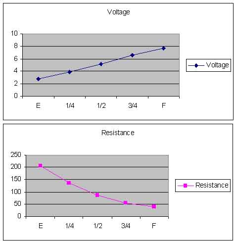
For comparison I have measured both my gauges at 61.5 ohms +- a tenth or so, and with just under half a tank I measure 90mA. That's with the original thermal stabiliser that switches 12v on and off about once per second, with an electronic stabiliser outputting 10v I'd expect to see about 70mA: Current-stock version of the locking-ring type, with a plastic base and three terminals. The centre terminal is earthed with the black wire, and the green/black wire goes on the top terminal. The bottom terminal should be covered with a plastic sleeve and is unused as that is for a 'low fuel level' warning that the MGB does not have. Note that all three spades on this type of sender seem to be the same size, so the connector on the harness will need to be replaced, or an adapter made up: Moss UK
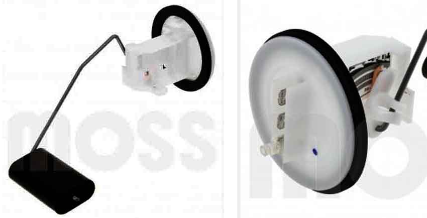
The plastic version, float nearer the side of the tank as pre-76 so the gauge reading is still affected by cornering. The centre terminal must be earthed to a point nearby with the provided wire as there is no earth wire in the harness of these cars. The original sender had a metal base and relied on earthing via the tank mounting, not possible with this plastic base. The harness wire goes on the top terminal, and as above the bottom terminal should be covered with a plastic sleeve: Moss UK
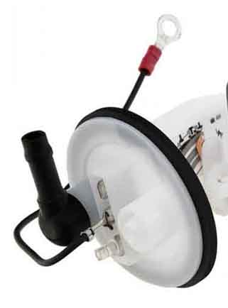
September 2022: Incidentally the black plastic right-angle hose connector on this sender seems to be a push-fit to the sender body. Mark Morris had a couple of problems - pump chattering when it shouldn't, then a leak from that connection - certainly the latter and probably the former from a split O-ring seal on that connector. The usual suspects only supply the complete sender, but he got a suitable replacement seal from a local motor factor. The original metal 77 and later senders had a metal pipe almost certainly brazed to the metal base-plate: (MGEXP)
Note that for some reason the installer of this used the later sender on an earlier tank, which has the original port with a short length of hose and a bolt plugging the end. It's possible this was done because the original pick-up pipe inside the tank had rotted through meaning the full contents of the tank were not available:
'A' - the earth connection to the earth track 'B'; 'C' - the output track; 'D' - the linked wipers that connect the earth track to the output track as the fuel level changes. The float is in the 'full tank' position so the wipers are connecting the earth to the output with just the minimum value resistance (left arrow from 'F') in series; 'E' - the output terminal; 'F' - the network of resistances that cause the sender resistance to vary with the fuel level; 'G' - not used on the MGB, the 'low fuel' track which outputs an earth on the third terminal when that wiper (not fitted for the MGB) reaches the point indicated:
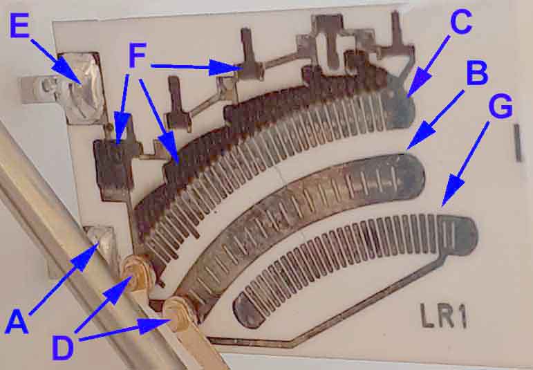
The resistance track comprises a network of series and parallel resistances that increases resistance in a non-linear fashion to match the non-linear characteristics of the thermal gauge. The 'sawtooth' section indicated by the middle arrow of 'F' consists of a line of individual resistances in series with each junction connected to a short piece of the track 'C'. The first 'tooth' with 6 segments, then 10, another 10, then 4, and finally 4. Within each 'tooth' the segments get progressively shorter as the fuel level drops, so even though the resistance is increasing from segments being added, it is increases less and less with each segment. Near the beginning of each 'tooth' a parallel path is added back to the output via another resistance, so each 'tooth' consists of a number of different resistances in series, with another resistance in parallel with those series resistances, and there are five sets of those in series with each other. This creates a much more nuanced change in resistance as the wiper moves along the track than is possible with the original wire-wound sender, which only has one basic change in former shape (and hence the length of each turn) and one change in the spacing of the turns across the whole of its range of movement. Despite that and the non-linear markings on the gauge which are another attempt to match the tank contents to the gauge indication, my gauges at least move a lot more rapidly from 1/2 to 1/4 then they do anywhere else, a 'feature' which has startled me more than once. Whether this new sender has been designed to replicate the original, or whether they have taken the opportunity to better match tank contents to gauge indication, I don't know.
Schematically the circuit is somewhat as shown here, the double-headed arrow is the slider that moves around the arc as the contents vary, currently showing as a full tank:
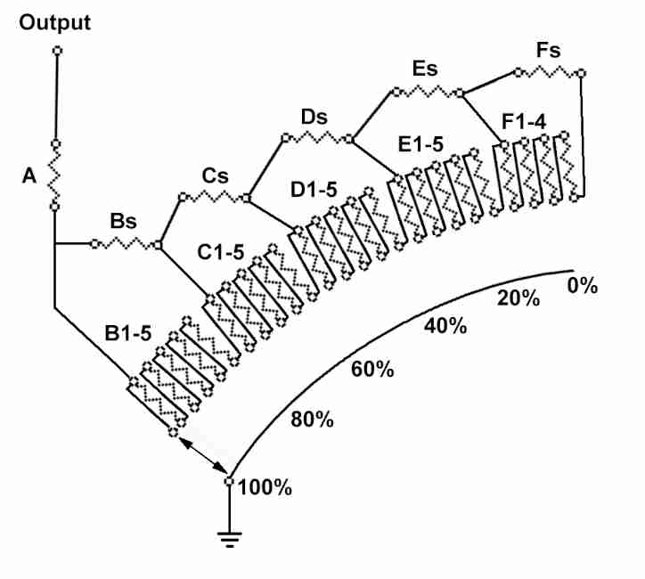
With a full tank the earth goes through the slider, bypasses resistors B to F, and through resistor A to the output, which gives the minimum resistance of about 20 ohms. When the fuel level starts to drop the slider moves to contact B1. All the C, D, E and F resistances are bypassed but a small portion of the current can flow through B2 to B5 and back towards the output via Bs, which are all in series with each other as well as being in parallel with B1. With two resistors in parallel the effect is to lower the overall resistance, for example if a 100 ohm resistor is connected in parallel with a 10 ohm resistor the overall resistance will become 9.09 ohms (you can try your own values here), so B2 to B5 and Bs will only reduce the effect of B1 by a small amount. As the slider moves through B2 to B5 the series value increases each time as each segment is added to the previous one. The parallel value is reducing as this happens, but the overall effect is a non-linear increase in resistance which takes account of the non-linear action of the fuel gauge.
When the slider moves to the bottom of C1, that resistor is now in series with Bs and A, with B1 to B5 being in parallel with Bs. Additionally a small proportion of the current is now passing through C2 to C5 and Cs all in series, which are all in parallel with C1, as when the slider was on B1, and again the series resistance increases as the slider moves through C2 to C5, with the parallel resistance reducing, but the overall effect increasing with reducing tank contents, of course. The same happens through D, E and F.
As well as this network of resistances causing the overall resistance to increase in a non-linear fashion to match the characteristics of the gauge, the 'sawtooth' appearance of each section implies the individual resistances change one to another adding to the non-linearity, which may well give a more accurate indication of contents than you can get with the original wire-wound type. At the time of writing I have no personal experience of this type of sender to see if that is the case.