


Speedometer
Tachometer
Instrument Voltage Stabiliser
Fuel Gauge
Tank Sender
Calibrating the gauge
Dual oil-pressure/temperature
Electric Temperature Gauge
Electric Oil Gauge
Gauge seals
Instrument Lighting
|
|
|
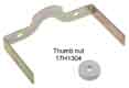
The smaller gauges are secured in the dash with a small 3BA knurled nut (thumb nut) 17H932 and various U-straps. Early gauges have external illumination with strap AJH5185 (fuel) and AJH5186 (dual) that carries the bulb, later gauges with internal illumination use AJH5187.
The electric gauges are usually powered from the green circuit (fused ignition), the one exception is the early electric tach from 64-67 which was powered from the white (unfused ignition) as well as having another white coming in to the pickup from the ignition switch and going out to the coil. I have no experience of electric temp and oil gauges in MGBs but the following info on fuel gauges may be of some use in faulting them. What I can give is the wiring colours. All run off the green circuit, either direct or via the voltage 'stabiliser' as follows:
- Fuel: 62-64: green circuit - fuel gauge - green/black - tank unit - black - boot earth
- Fuel: 65-on: green circuit - stabiliser - light-green/green - fuel gauge - green/black - tank unit - black - boot earth. From about 75 on for North America, and 77 on for the UK, there was no longer a wired earth at the tank sender.
- Temp: (North American spec 67-on, UK spec 77-on) green circuit - stabiliser - light-green/green - temp gauge - green/blue - temperature sender
- Oil: North American 67/68: green circuit - stabiliser - light-green/green - oil gauge - white/brown - oil pressure sender
- Oil: North American 69-71: green circuit oil gauge - white/brown - oil pressure sender. From 72-on North American spec reverted to a mechanical gauge
Faults and Repairs
Gearbox Drive Gears
Pinion Housing
Cables and Routing
EGR Valve Service Indicator
Right-angle drives
Decals
Cruise Control
 There were many different speedos used over the years (I have found 50 so far!) according to year, market and vehicle spec.
 Secured into the dash with two large 3BA knurled nuts 17H1304 and spring-washers, with a U-strap AJH5176 to September 64, separate 'legs' 17H3744 on each threaded stud from then until July 74, and 17H1339 until the 1977 model year. 1977 and later have a much better arrangement where the speedo and tach have three studs in the instrument case, and by turning them clockwise 30 degrees these studs will align with cut-outs in the dashboard to allow the instrument to be withdrawn. Unfortunately LHD only.
As well as the obvious physical differences in size and markings the 'turns per mile' (TPM) varied over the years, that is
the number of turns of the speedo cable to register a mile travelled. This has to be matched to the drive gearing in the gearbox output shaft, the rear axle ratio, the wheel size, and to some extent the tyre size. Get the TPM wrong and both speed and distance travelled indications will be incorrect. Speed is relatively easy to compensate for by making internal adjustments but to correct the odometer different gear sets are required. The table below has been developed largely from the Leyland Parts Catalogue and Clausager and examination of many speedos at autojumbles, with additional information from other sites such as NAMGBR, Autochart
and Paul Tegler. However these other sites either don't include TPM figures, are limited in scope, or disagree to some extent with information from other sources.
I am indebted to Ian John of Caerbont Automotive Instruments for supplying me with a list of TPMs for these speedos.
Note that speedos not in the list with the exact reference number, even though they have the correct TPM figure, may have different speedo cable fitments, or night-time illumination/ignition warning lamp/main beam tell-tale or fitting arrangements, making fitting them in an MGB not straightforward.
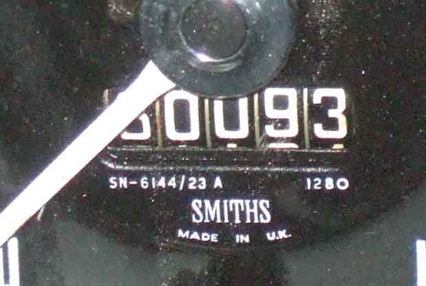
Updated August 2010: Note that 1280 tpm overdrives were used V8s and 4-cylinder chrome bumper cars (the latter having a black label) whereas 1000 tpm ODs were used on 4-cylinder rubber bumper cars and had a blue label. Thus on V8s there seems to be a mismatch between the 1280 tpm overdrive and the 980 tpm speedo, but this is almost exactly counterbalanced by the different axle ratio used on the V8. See here for more information on label colours.
Lights: July 2020
 Instrument illumination is at the top, the bulb-holder (single wire, red/white) is push-fit, but usually pretty tight so may need to be pulled to one side to get it free. CB cars main-beam bulb (also single wire, blue) is at the bottom, also push fit but much easier to get out and back in.
I've had a copy of a Repairing Jaeger & Smiths Speedometers document by Anthony Rhodes for a long time. That used to be online although harder to find now, it has been rewritten into a web site for Sunbeam Tigers. The Tigers web site has more written information (albeit over 17 pages which is a bit inconvenient), but the original document has more pictorial information and is easier to scroll back and fore, hence both are linked from here.
However with Bee's 4" speedo it was nothing like as easy to get the guts out of the case as Rhodes states. The trip reset protrudes much too far and will not 'push into the case' as described, and it only allows the mechanism to be moved forwards a few mm with the rear screws removed. I did not fancy trying to remove the pointer from that tiny spindle, so removed the screws holding the dial to the mechanism and with that free to move about under the pointer, and pushing the rubber gasket around the rear shaft up into the case, gave me just enough room to manipulate the mechanism out of the case. However trying to replace it the pointer did ping off - fortunately not snapping the spindle as I first feared, but leaving me with the problem of where to reattach it. That was done successfully, and on a subsequent occasion slotted the hole in the case for the reset shaft and that allowed removal without removing the dial screws.
June 2024:
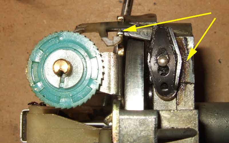 Noticed Vee had clicked over to 30k ... then the next trip it out was just the same! Five minutes saw the speedo out (both cars came to me with only the tach-side mounting leg installed which can be accessed by reaching up behind the tach), another minute it was out of the case, and the main driving wheel was jammed. All the wheels were jammed, including the 10k digit, so it looked like that had failed to complete its turn and jammed all the way back. On the desk upstairs I consulted my previous experiences with the odo and just by removing the blue driving wheel and giving things a wiggle there was a click and everything was free again, and that had taken another five minutes. Back together turning a screwdriver in the cable drive started advancing the tenths wheel, and a drill and end off a broken cable drove the speedo round to 140mph with the tenths advancing merrily. I wanted to put the known 'missing' miles back on, but that way would have taken ages with the drill, so back out of the case again turning the driving wheel beside the tenths with a thumb soon put 75 miles on pending a trip out and refuel to give another estimate of mileage but it was about right so fastened back in the dash. Which took three goes feeling for the stud with the 'leg', earth wire and spring washer on, and a bit of a fiddle to get the knurled wheel started but no more than ten minutes. Will it happen again at 40k? Watch this space ...
May 2021:
 Guy Renou has written to say he was able to remove the pointer surprisingly easily by putting a cloth over the dial, then using the curved tines of a table fork to gently lever it off! With the dial then removed you should be able to manoeuvre the mechanism out of the case with the rubber gasket pushed inside the case, but it does need to be orientated in a particular way, and again to get it back in. But with the dial off you can remove the small circlip from the reset shaft which allows the shaft to be removed, then the mechanism comes straight out.
April 2024:
 Suddenly had the thought that trim removal tools could be used to remove the pointer ... and they can.
July 2020:
 On the way up to the Lake District Vee's speedo started flicking and I wondered whether it was the new cable that had been in about 500 miles. Then it started flicking higher and higher, and when it got to 120, 140 and then the back of the needle stop I knew it had to be the speedo itself. Finally it stayed at the back of the needle stop until we came to a halt when it slowly returned to zero, going round to the stop as we started moving again, confirming it was the speedo. Back home it took about 10 minutes to get the speedo out and opened up (much easier than Bee's) and the problem was immediately obvious - black oil in the mechanism and causing the spinning magnets to pull the needle cup round by much more than the usual magnetic force.
Note that it is not magnetism that drives the needle cup directly but induced eddy currents, as the cup is aluminium which is non-magnetic. What happens is that the spinning magnet induces a current in the aluminium cup, and the effect of that current flowing in the aluminium is to generate an equal and opposite magnetic field which opposes the field created by the spinning magnet. This opposition cannot slow down the spinning disc, so it causes the needle cup to be dragged round. This effect has been used in electricity meters and to control the speed of roller-coasters and high-speed trains for many years. For the roller-coaster all it needs is permanent magnets on the car, and aluminium vanes on the track. No power supply, no moving parts, nothing to go wrong.
December 2014: 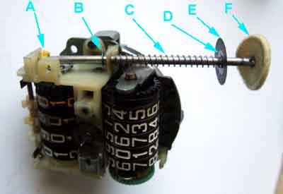 I needed to get into the mechanism in order to modify the mileage reading. Bee's trip odo has been jamming regularly this year, which made following Tulip instructions tricky. Fortunately the tenths was still going round, so I was having to add that to the main odo reading, then add to that the next inter (distance to the next turn) for the Navigator to write down. Bad enough, but because the trip and main odo aren't in synch sometimes I ended up a mile out either way. I was going to send it away over winter to be repaired, there are a couple of people who can then set any mileage you require (ordinarily it would be zeroed), but at £90 it's quite pricey and they take several weeks to do it. I'd got to the point of investigating how much new ones were for insurance purposes if mine should get lost, when I thought of looking for used on eBay. I found two, one was exactly right for Bee going by the reference number on the dial at £40. The other wasn't a very good picture but from what I could see looked right, at £20 in 'good condition and fully functioning', both mileages way different to Bee's of course. No shipping price in the ad, and you don't get that until you commit to buy which isn't helpful. Emailed the seller asking them to confirm the numbers and shipping price, but had to wait several days for a reply. Not exactly right - it was originally used on 74 models, but specified in the Parts Catalogue as being backwards compatible with earlier Mk2 cars so fine for me, and shipping a reasonable £5. By that time the £40 one had gone, so I committed to buy this one, then had to wait another week or so with no further info from the seller as to whether it had been shipped or not, before it turned up. First thing I did was test it with my drill on reverse, and the speedo goes smartly round, but neither bloody odo worked! Annoying, as the face and the numerals were in as-new condition, and the bezel and glass were no worse than Bee's. I could have sent it back of course, but more hassle and aggro, and no further forwards. So for the sake of £20 I decided to use it as a learning experience and open it up and have a look at it. Same problems with getting the guts out as with Bee's, which I'd already tried months earlier in an effort to see what was wrong with her trip. See the full story here on fixing the odometers on both speedos as well as a description of how they work.
Speedy Cables is often mentioned as a source of speedo repairs, but there have been complaints of these taking several weeks.
I used Speedograph Richfield to recalibrate Vee's speedo as part of a 5-speed conversion. It had to go back a second time as they hadn't replaced dirty odo wheels, and when it refitted it over-read by a full 10% which was annoying, until I reset the pointer on the shaft.
JDO Instruments offers a 48 hour turn round which has been verified by members of the MGOC MGB Technical forum. But for the purposes of balance someone ringing JDO about a repaired speedo that had failed had the phone slammed down on him with the words "I'm 80 years old and I don't need this", and someone else said he had used Speedy Cables with prompt return.
So there you are - your choice.
Speedo Drive Gears: March 2008
Looking at the parts lists there always were different speedo drive gears and pinions, with different ratios, between non-OD and OD. But whereas the ratio difference is nearly 3% for the 3-synch gearboxes, it is only 1% for the chrome bumper 4-synch (I don't have all the ratio information for the rubber bumper cars). 1% is insignificant (given that speedos in the UK are allowed to over-read by up to 10% but not under-read) so having the same tpms for both is reasonable, but why the different speedo part and reference number if everything else is the same? Even 3% difference for the 3-synch is not that significant in the grand scheme of things, but the speedo tpms for non-OD and OD cars did take this into account. Although even that isn't straight-forward, as the information I have is that Jaeger instruments were 1060 for non-OD and 1040 for OD, whereas the later (1964) Smiths were 1040 for non-OD and 1020 for OD! Whilst the change from crossply tyres to radial may have required a change in gearing, radials weren't available until 1965, and crossplies remained standard on UK cars until 1972.
The bottom line is that while changing a non-OD gearbox to an OD gearbox using 3-synch will introduce an error of nearly 3%, on a 4-synch car changing from a non-OD to an OD gearbox of the same era will only introduce a 1% error and can be ignored. The important thing to remember on 4-synch 4-cylinder cars is that the OD units changed from a black label to a blue label between CB and RB so if you put a rubber bumper OD gearbox in a chrome bumper car or vice-versa, and don't change the speedo, you will introduce an error of around 20% which is very significant. However the speedo size changed at the same time so it's not simply a case of fitting the speedo that came from the same car as the gearbox. V8s used a black label on both CB and RB, so no change in speedo tpm and all V8 tach and speedo instruments are 80mm.
Paradoxically using a 3-synch speedo on an RB car or vice-versa would only introduce a 2% to 5% error, unfortunately the speedos are different sizes at 4" and 80mm on RHD cars. One of the great mysteries of life is why LHD cars reverted to 4" from 80mm for the latest plastic dash in 1977 when RHD stayed at 80mm. On the face of it one of those would fit, but RB speedo and tach don't have provision for the ignition and main beam warning lights.
What speedo drive gears and pinions were used, where and when:
| Gearbox | Worm Gear | Starts | Pinion | Teeth | Ratio | |
| Chrome bumper 4-cylinder | 3-synch non-OD (dipstick level/filler) | 1H3369 (white plastic) | 9 | 11G3264 (white plastic) or 22H1420L | 28 | 1:3.111 |
| 3-synch OD (dipstick level/filler) D-type OD | 7H8294 (metal) | 5 | 17H8021 (metal?) | 16 | 1:3.2 | |
| 4-synch non-OD (dipstick level/filler) and Auto | 22B468 (metal) or 22B649 (white plastic) | 10 | 22B654 (white) | 26 | 1:2.6 | |
| 4-synch OD (dipstick level/filler) LH-type OD (black label) | 37H3464 (blue) | 8 | 37H3463 (white) | 21 | 1:2.625 | |
| Rubber bumper 4-cylinder | 4-synch non-OD (side-plug level/filler) | DAM686 (black) | 9 | DAM687 | 30 | 1:3.333 |
| 4-synch OD (side-plug level/filler) LH-type OD (blue label) | 37H8844 (red) | 6 | 37H8845 (red) | 20 | 1:3.333 | |
| All V8s Note 1 | 4-synch OD (side-plug level/filler) LH-type OD (red label but see Note 2) | 37H3464 (blue) | 8 | 37H3463 (white) | 21 | 1:2.625 |
Note 2: Label colours are nominal, with MGC having green according to one source and V8s red, however my V8 is black and Geoff Dunlop's in Australia is green. Ex Laycock people at Sheffield Overdrive Services have told me that if they didn't have the right colour available they used whatever they had to hand albeit stamped with the correct reference and serial numbers.
'Starts' refers to the number of threads on the worm gear fitted to the gearbox output shaft (a standard bolt only has one start). The number of starts is another way of setting the ratio between worm gear and cable drive pinion, the greater the number of starts the faster the pinion turns in relationship to the worm gear. This Wikipedia page explains the principle very well and has an animated graphic demonstrating a 4-start worm gear.
SC Parts Group has exploded diagrams of all the OD components (as well as the gearboxes) for all the MGB variants. All the pinions and drive gears are priced, implying that all are available.
Pinion Housing: August 2020
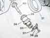 The LH OD housing (non-OD and D-type are different) has an O-ring seal to the gearbox body and a lip-type seal in the housing to prevent leaks from the pinion shaft. After replacing Vee's cable the new one is drawing oil up the cable to contaminate the speedo, so investigation with a view to seal replacement was called for.
 Why is this cable drawing oil up when the old one hadn't? There is a seal on the drive spindle, which seemed initially to be missing so I fitted one, but subsequent research indicated it should be well into the housing so one is probably already there. Checking about 50 miles later more oil has worked it's way about one quarter the way up again, so I'm going to have to get the housing and pinion out for inspection and replacing the original seal - probably with yet another new one. That means working with the back of the car as high as possible to limit the amount of oil that can run out, but some is bound to.
Late October after a 200-miler I take the speedo cable inner out ... and it was slathered in oil again right to the top. So oil still getting into the cable somehow, but the inside of the speedo was clear so maybe just caught it in time. Next step will be to disconnect the cable from the gearbox and see if anything drips out, and keeps dripping. Also to check the oil level and colour to see if it is as black as what's in the cable.
Early November I check the gearbox and the oil is clean as it should be, so the standard lubrication of the new cable is what must be blackening it. The level hasn't dropped in fact it's a bit high so I let some trickle out. Started removing the cable and the knurled nut didn't seem to be turning more freely or the cable coming loose in the nut, then I noticed the housing was turning! So out from under and back again with a selection of spanners to tighten the forked clamp that holds the housing in, didn't go fully tight, but after a few flats I tried again and this time the knurled nut came free. No oil came out, but I jacked up one rear wheel and ran it in 1st gear for a few minutes with the cable removed, to find a tiny drop of oil where the pinion exits my extra seal, so the housing will have to come off and the seal and pinion removed, examined and maybe replaced. I could replace just the seal at a few pence, but if the problem is the pinion it'll only happen again, and if I think it's fixed I probably won't know until the speedo packs up again. A pal had an OD rebuilt and the drive flange oil seal leaked straight away, they sent him a new seal and flange, so I'd expect the same.
Still under guarantee from the rebuilder (who sent the OD elsewhere) and he says if I can get them out to see what needs replacing he will contact the OD rebuilder. That's complicated as it may take a while to get the parts, I could get them locally but why should I? Also the back of the car would need to be raised quite a bit to prevent oil running out from the housing hole - OK for a removal and replacement with parts to hand, but I don't want to leave it like that. So it'll need draining. But unless I can catch it in a clean container for reuse that means another £40 for oil - which is almost twice the parts! I can use an empty oil can from an engine oil change earlier in the year as they are clean. But that will need a funnel or it could be very messy, and the funnel needs to be bigger than the drain hole or the funnel will overflow! Also the car needs to be high enough to get the can and funnel underneath and still leave space for me to remove the drain plug, without dropping it, for if that goes in the funnel it will block it and overflow!! But up on my full-length ramps it should be high enough, and will be level so safe to leave with the housing out for a while if needs be, but I'll need an oil change drain bucket to hand just in case, which will mean losing the oil. So much to think about and plan for, and yet another saga.
Late November: I decide to drain the oil so I can get the car up on the full-length ramps for ease of working underneath. I have an almost empty plastic 5L engine oil can with a short flexy spout. That and its housing can be levered off to leave a large hole in the can, which an old 1L gear oil container with the spout removed fits neatly inside to act as something of a funnel - I don't fancy unscrewing the drain plug and trying to get the sudden flow in the can otherwise without making a right mess. Underneath the drain plug moves easier than I expected - I don't think I checked its tightness on reinstallation! Too much room now, I'm going to have to hold the can and 'funnel' up closer to the gearbox while I'm undoing the plug. Do it over one of my large plastic drip-trays - just as well as some does run down the outside, but at least I don't drop the drain plug in as well, which was another fear. Drains in a few minutes so refit the plug - tightly! Only 2.25L in the can with 3.4L capacity quoted in the manual, something that figures as after draining and up-ending the gearbox after removal, then laying back down again, I did get quite a bit more out. Hope the remainder doesn't run out of the OD with the pinion housing removed!
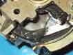
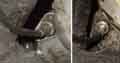
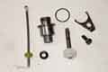 7/16" spanner to remove the bolt holding the forked clamp for the housing, and the housing starts sliding out on its own. Get the drip tray underneath while I fully remove it, thankfully no more oil. On the bench I remove the O-ring that seals the housing to the OD casing and the pinion slides out. A long fine scratch the length of the shaft i.e. passing through the oil seal - source of the leak? Closer examination shows witness marks from the seal round the shaft, but there is a definite gap part way round which indicates that part of the shaft was not in contact with the seal, and so a more likely source of the leak. My extra seal comes out easily enough, and is a good fit to the pinion shaft in terms of the resistance I can feel, but with the pinion back in the housing there doesn't seem to be any extra resistance from the original seal than there is from the housing itself. Now how to remove the original seal, which is well recessed in the housing?
Really it needs some kind of puller that goes in from the speedo cable end, with fingers that go through the seal and can lock behind the metal surround. Then the housing would need to be held firmly while the seal was pulled out - back in the OD!? I opt for bending the end of an old flat-blade screwdriver towards a right-angle, and rounding the ends, to put in from the pinion end and drift it out rather than be pulled, and after a bit of tweaking that does the trick. While writing this I Googled 'small oil seal puller' and found someone else had done exactly that! Someone on that thread mentioned drilling and putting in a sheet-metal screw and pulling it out with that which I know can be done with larger seals but I think this is too small. However it did occur to me that a large screw through the centre of the seal biting into the metal surround might do the same job, but you would have to avoid damaging the part of the housing the pinion shaft runs in which is very close to the seal. Other possibilities were a pick with the tip partly curled back on itself, and other gadgets too complicated to explain and a lot more expensive. Anyway, it's out now.
 Two problems immediately apparent - one is a fine scratch the length of the pinion shaft which may well be too fine to cause a problem, but the other concerns the witness mark of the seal on the shaft. There is a distinct gap in the witness mark, as if the pinion shaft has a slight flat at that point and isn't touching the seal, and I can definitely imagine that resulting in a leak. I email pics of both those areas to the gearbox man, together with a phone call, asking for replacements of pinion and both seals from the OD rebuilder, so Vee is out of action for the time being. If they refuse to cough up at least I can get them from Leacy's when I collect the front screen.
Time to ponder fitting the new seal - fill the (small) gap between seal and housing with grease as an additional measure? At the very least it would lubricate the new seal and pinion shaft before oil works its way down. A second seal again but pushed all the way down if there is enough plain shaft left on the pinion spindle?
 Tony at Geartech gave me the number for David at Overdrive Spares in Rugby who overhauled the OD and he sent me a new pinion, seal and O-ring with no quibble. When they arrived I tried the new seal on the new pinion and it seemed a much better fit than the old pinion had been in the old seal. Prior to fitting the seal I injected some grease in the seal end of the housing then pressed the seal into the housing using a suitably-sized socket. I then fitted the old pinion just into the seal from the 'wrong' end, and fitted the new pinion from the correct end, the intention being to squeeze the grease between the two pinions to fill the cavity between the seal and the shoulder in the housing, which worked well. Otherwise the end of the pinion would have pushed the grease straight out of the seal without spreading it round to fill the gap. Fitted the O-ring and bagged the assembly up prior to refitting tomorrow. The question then, will be whether to run the gearbox and overdrive after putting the oil back but before refitting the speedo cable ... or just to go for it. I wasn't bothered about doing that jacked up with one wheel removed when the car was on the ground and the wheel ramps, but doing that on the full-length ramps is a less attractive proposition.
What a pain in the backside that was! It's bad enough that the housing is above the fixed crossmember with the bulge of the OD one side and the narrowing tunnel the other, so even with a smallish hand I can barely get two fingers on the head of the bolt from behind, and with another finger on the other hand from in front I can't see the hole I'm trying to get the bolt in. Not that I can see the hole with the Y-clamp in the way, to know I'm in the right place to start turning the head. I tried using a long screwdriver to position the head and allow me to see but it flapped about all over the place, and I can't feel when the end of the screw is in the hole, let alone lined up. The threaded end of the screw is recessed from flat which makes it worse, so I file the edges off to make it slightly rounded, but still no go. So housing out and try the bolt without the Y-clamp and it goes in straight away. Try the bolt and the Y-clamp and still no go, but try a 7/16" 1/4" drive socket as a 'holder' for the bolt and eventually it goes in, after packing the socket with paper so enough threads protrude and to wedge the bolt. At some point during all this the bolt slips out and falls onto my neck while lying horizontally underneath, then goes into my shirt so I have to crawl out from under and delve in my clothing to find it. Back under again and I realise I'm missing the lock washer, so back out again and more delving to find that. I then come to the realisation that the problem is caused by the housing flange coming right up to the edge of the bolt hole, so whilst I can tilt the bolt in most directions to help align the threads there is a good 90 degrees or more where I can't tilt the bolt towards the housing, so it has to be dead on square while I'm turning it up to a full rotation to pick up the thread. I'm sure it's easy enough off-car where you can use a nut driver on the bolt head and attack it square on, but in-situ it would make it so much easier if the flange on the housing were an 1/8" or so smaller, it's not as if it needs to be as wide as it is. Eventually I do manage to get it started using the socket as a holder, but it has to be spannered in the whole way as it must be right up against the flange on the housing. I found the same when removing it but didn't think much of it, whereas without the housing in place the bolt went in easily with finger-tips. Another few minutes fiddle saw the speedo cable connected, and that 2 hours was more than enough for the morning session!
After lunch it's refill with oil, I have a 1L bottle with flexy tube with about 500mL left over from filling it after the rebuild, plus the 2.25L I drained out this time in a clean 5L 'can'. So about half a dozen trips under the car after filling the 1L container to squeeze in as much in the side filler as I can which is about half a litre each time, before crawling out again to top up. Eventually I empty the big container and oil starts running out of the side filler so refit the plug, and there is a shade over 500ml in the 1L bottle so not quite as much in now as before. I'll leave it to settle then try again another day after having run the gearbox and OD to be sure oil has got everywhere, but that means getting it off the big ramps which means getting both cars out which needs a dry day! Not that I mind as I'm pretty knackered after what should have been no more than a few minutes to fit the housing and attach the cable. Subsequently checked and all OK.
March 2021: Only a few dozen miles done because of the poor winter weather, but worth a check to see if any more oil is being drawn up. Some at the top which isn't surprising as the inside of the outer would have been coated all the way up and excess would have beef driven upwards as before, but nothing more than what would seem like 'normal' lubrication the rest of the way down and particularly at the bottom, so hopefully problem resolved. I've not refixed the speedo back in the dash yet though until I've done a good few more miles, hopefully a 200-miler to son's and back ... when it's allowed!
April 2021: An Easter trip to son's sees said 200-miler sees the inner out next day. Only a little more than I would expect at the top and 'normal' at the bottom so it looks like the seal has done the trick, but I still only put the speedo back temporarily. Just as well as when I went out in the car the speed wasn't registering but miles were ... odd. Took it out, spinning a screwdriver in the cable drive registered on the speedo, so back in, but still no speed. Waggled it in the dash and the needle went up a bit ... then stuck there! Back out again needle has returned, took the mechanism out of the case and can't find anything wrong. Back in the car,. and at some point a light-bulb moment - literally. I suddenly remembered that when fitting LEDs to the instruments I had to put a sleeve on the speedo holder to stop it going in as far as the longer LED 'bulb' was interfering with the needle disk! Somehow each time I had put the LED back in I had contrived to push it in too far, and withdrawing it a little solved the problem. Phew! Still haven't fully refixed it back in the dash though.
Speedo cables March 2010
Erratic readings
Cable Replacement
Cable Routing
| Chassis No. | Gearbox | Cable | Length | Notes
| 101-9402 | (May 62-Mar 63) 101-138400 (May 62-Oct 67) RHD | LHD non-OD | GSD103 | 1143mm | (45") It seems highly unlikely, if not impossible, for RHD and LHD cables to be the same length | 101-10611 | (May 62-Apr 63) RHD | OD | GSD116 | 1422mm | (56") Not listed, some suppliers show GSD115 as 57", but GSD117 at 60" allows the speedo to be pulled forwards far enough to remove/refit that end in front of the dash rather than behind. | 101-138400 | (May 62-Oct 67) 10612-138400 (Apr 63-Oct 67) LHD | RHD OD | GSD117 | 1542mm | (60") It seems highly unlikely, if not impossible, for RHD and LHD cables to be the same length. | 9402-138400 | (Mar 63-Oct 67) RHD | non-OD | GSD111 | 1219mm | (48") | 138401-410000 | (Mk2-Jun 76) RHD | non-OD | GSD249 | 991mm | (39") | OD | GSD116 | 1422mm | (56") Not listed, some suppliers show GSD115 as 57", but GSD117 at 60" allows the speedo to be pulled forwards far enough to remove/refit that end in front of the dash rather than behind. | 138401-153877 (Canada) | (Mk2-Aug 68) 138401-187210 (roadster) (Mk2-Oct 69) 138401-187840 (GT) (Mk2 - Sep 69) LHD | non-OD | BHA4596 | 1270mm | (50") not USA, Sweden, Germany | OD | GSD151 | 1829mm | (72") not USA, Sweden, Germany | 138401-282419 (USA) | (Mk2-May 72) 153878-282419 (Canada) (Aug 68-May 72) LHD | non-OD | GSD104 | 1373mm | (54") North America, Sweden, Germany, without service indicator | 138401-410000 (USA) | (Mk2-Jun 76) 153878-410000 (Canada) (Mk2-Jun 76) LHD | OD | GSD151 | 1829mm | (72") North America, Sweden, Germany, without service indicator | 187211-328800 | (Oct 69-Aug 73) RHD | Auto | GSD103 | 1143mm | (45") | LHD | Auto | GSD116 | 1422mm | (56") not USA, Sweden, Germany. | Not listed, some suppliers show GSD115 as 57", but GSD117 at 60" allows the speedo to be pulled forwards far enough to remove/refit that end in front of the dash rather than behind. GSD117 | 1542mm | (60") North America, Sweden, Germany, without service indicator. | 282420-410000 | (May 72-Jun 76) LHD | non-OD | GSD145 | | North America, Sweden, Germany, without service indicator | 360301-386600 (Canada) | (Sep 74-Sep 75) 360301-422791 (Sep 74-Jan 77) LHD | non-OD | BHA5351 | | North America, Sweden, Germany, gearbox to service indicator | OD | BHA5360 | 1016mm | (40") North America, Sweden, Germany, gearbox to service indicator | all | BHA5359 | 584mm | (23") North America, Sweden, Germany, service indicator to speedo | 410001 on | (Jun 76-on) Whilst all previous cars seem to have the same sized fitting at the speedo end, RHD cars from this date, and from what I can tell LHD cars as well, have a bigger fitting so are not compatible with earlier cables, and vice-versa. RHD (all) | OD | GSD315 | 1450mm | (57") | LHD | non-OD | AAU3868 | 1200mm | (47") without service indicator | OD | AAU3870 | 1700mm | (67") without service indicator | All V8 | RHD | OD | GSD116 | 1422mm | (56") Not listed, some suppliers show GSD115 as 57", but GSD117 at 60" allows the speedo to be pulled forwards far enough to remove/refit that end in front of the dash rather than behind. | |
Speedo Fitting: May 2021:
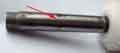
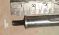 Someone having problems with erratic readings which JDO said might be because the cable inner is pressed into the speedo too far. Cables do vary, with 77 and later appearing to project much further than previously, so I've taken some measurements, see the detail from clicking the attached thumbnail.
Under reading of both the speedo and odometer can be caused by the gearbox drive flange nut not being tight enough (the drive gear is not splined into the shaft), D-type OD should be 100 to 130 ft lb, LH OD 55 - 60 ft lb, non-OD 150 ft lb. See here for how to hold the flange still while tightening (or undoing) the nut.
Regular downward pulsing of the needle, if coincides with the ODO tenths wheel moving, can be caused by a dry cable or speedo input shaft, a single drop of oil on the end of the shaft will cause no harm. If it flicks more frequently than that it is probably broken strands in the inner.
Cable Replacement: March 2020
 Vee breaks her cable and as well as the turmoil created by Coronavirus and companies trying to keep going with people working from home, the part numbers and lengths are very variable between suppliers, which led to some head-scratching.
Eventually resolved that, then about 150 miles later on our way up to the Lake District in July the speedo started flicking - damned new cable, I thought. But the flicks were upwards, getting higher and higher, until eventually the needle went all the way round to hit the back of the stop. Until we came to a halt, when it slowly went back to zero again, only to move all the way round again as soon as we started moving. That's got to be the speedo itself, and proved to be oil having worked its way up the cable and into the mechanism, acting as a viscous coupling between the spinning magnet and the needle disc. Eventually got that cleared, but not without damaging the main ODO in the process although I was able to replace it with the one from Bee's old speedo. Cleaning the cable an a few more miles showed more oil - so why not with the old cable? But all I can do is investigate the pinion housing.
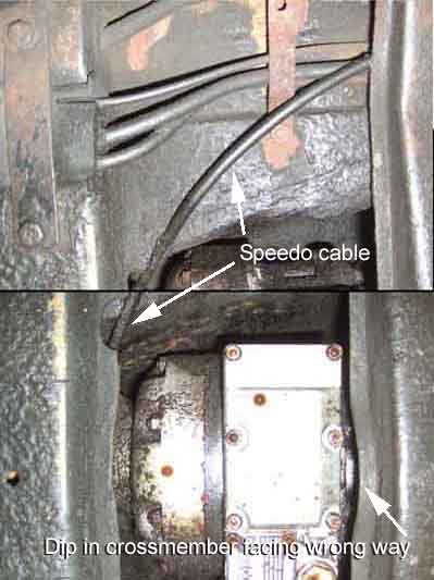 On OD gearboxes the cable attaches further back on the output of the OD and above the fixed cross-member. This cross-member on 4-synch cars has a notch which together with the connection being angled slightly forwards allows the cable to leave the gearbox at almost a right-angle, the bulk of the curve turning forwards being in front of the cross-member and under the floor. Early cars do not show this notch (Clausager p76), but 3-synch gearboxes with the earlier D-type OD do seem to offer more space to allow a right-angle drive to be used. However if a broken right-angle drive on a non-OD gearbox was not replaced (they are expensive) this may need a slightly longer cable to avoid a tight turn.
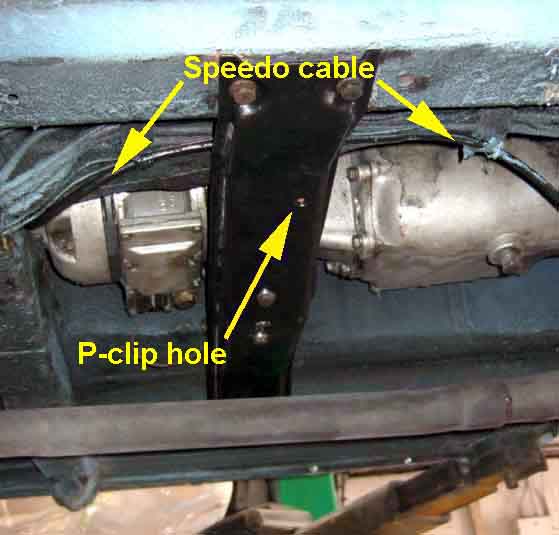 It should then pass under the removable cross-member and be supported by a P-clip, however both Bee and Vee have theirs above and cable-tied to the other cables and pipes. In Bee's case the cross-member is the wrong way round so the tapped hole is on the other side. And whilst Vee's is correct, and I could have fitted it in the correct position, where they are is more protected from any rocks, traffic-calming measures etc. and as neither have exhibited any problems in my ownership where they are I've left them be (until I replaced the cable).
 Clausager shows a clip holding it to the tunnel wall by the clutch slave on a Mk1, no reason to assume it isn't the same on later cars although neither Bee nor Vee have it.
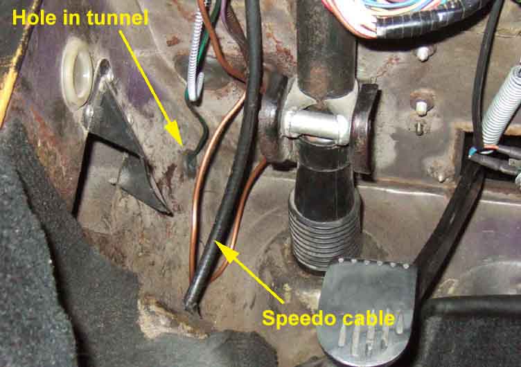 On RHD cars it passes through the bulkhead via a hole in the top of the drivers footrest, and from there makes a graceful turn up and back into the RHD speedo head.
There is also the question of right-angle drives.
 The Parts
Catalogue doesn't show or list one with the 3-synch standard box but does show and list 13H2567 (120694) with the D-type OD. The drive on the 3-synch standard box exits pointing slightly backwards, and on the D-type OD comes out at a right-angle to the line of the gearbox, which means especially for the non-OD gearbox a right-angle drive allows the speedo cable to run straight forwards and makes sense.
The Parts
Catalogue doesn't show or list one with the 3-synch standard box but does show and list 13H2567 (120694) with the D-type OD. The drive on the 3-synch standard box exits pointing slightly backwards, and on the D-type OD comes out at a right-angle to the line of the gearbox, which means especially for the non-OD gearbox a right-angle drive allows the speedo cable to run straight forwards and makes sense.
It lists but doesn't show the same item for 4-synch non-OD boxes but lists and shows it for the LH-OD but is completely unsuitable for both. The drive is angled forwards, which not only makes it difficult to attach a right-angle drive and cable especially on the OD with its casting bulge right next to it, but the fixed crossmember has a notch to allow a longer cable to make a smooth turn direct off the gearbox or OD, and the removable crossmember has provision for a clip to support the cable closer to the chassis rail.
It lists but doesn't show it for the automatic box, but exiting at right-angles similar to the 3-synch it does need one.
 An important factor on BL gearboxes at least is the provision of copper spacer washer 3H550 between the angle-drive and the gearbox, usually listed in the Parts Catalogue with the angle-drive. Without that there are excessive end-loads on the angle-drive resulting in premature failure, possibly from the square drive shaft protruding too far.
What about the speedo end?
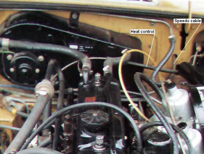 The Parts Catalogue indicates one for the speedo as well - BHA 4794 - for Sweden and Germany from chassis number 187211 (1970 model year), North America from 258001 (1972 model year) to 282419 (May 1972), then 13H2567 for apparently all 1977 and later LHD cars. It would have been needed where the cable came up into the right-hand footwell as for RHD cars (which is at the top of the clutch foot rest) then across the car behind the dash. This would have resulted in too tight a turn behind the LHD speedo in the limited space available, hence the second unit. A number of people with LHD cars have said their cable comes up past the RHD entry point, across the engine compartment at the heater shelf, then in through the bulkhead in front of the driver direct to the speedo, rendering a speedo head right-angle drive unnecessary. This includes 3-synch cars using the large hole under the hinge slot, although Clausager appears to show a 74 car routed in this manner but using a smaller hole further above and towards the centre of the car than the large hole (which contains the heat control cable?).
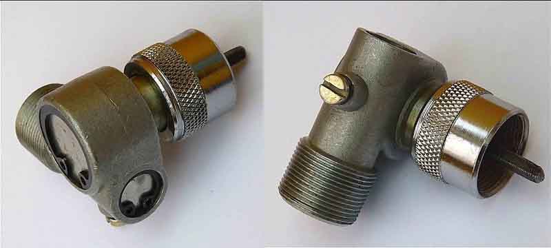
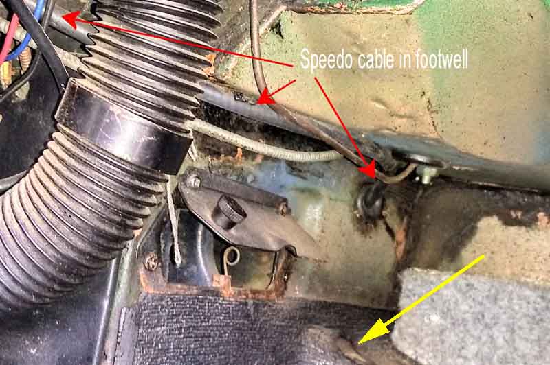 The question is what happened on LHD cars prior to the 1970 model year? Did they run across the bulkhead in the engine compartment like post-May 72 cars and hence not need one? If so it seems odd that they then brought it inside the cabin for two years, needing a second drive, but a different part to the gearbox one. But this 1968 model has the cable inside the cabin in the right-hand footwell, and has a right-angle drive on the speedo.
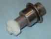
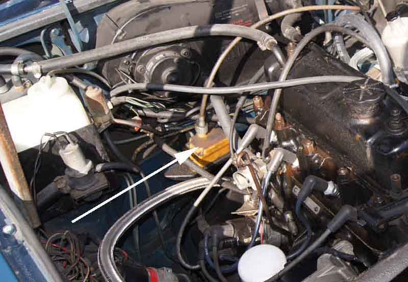 North American rubber bumper cars had an EGR valve service indicator from 1975 which was a warning light triggered every 25,000 miles. A resettable counter intercepted the speedo cable, and was positioned on the bulkhead as shown here on Bill Etter's car. The warning light was illuminated each time the car was started as a lamp test facility. The service indicator was deleted for Canada from 1976 on, and for the rest of North America from 1977 on, which ties in with one of the speedo cable changes listed above.
 Prior to the electronic tachometer a mechanical rev counter was used which was cable driven from the engine block. According to the Parts Catalogue the rev counter ended at chassis number 48765 and the electronic tach started at 48766. The engine changed from 18GA to 18GB at that time, but there was a short period when either engine could have been fitted. According to Clausager the 5-bearing was fitted intermittently from chassis number 47112 with all cars having them at chassis number 48767. This means that cars from 47112 to 48765 that got the 5-bearing would have had the electronic tach as well as there was nowhere on the 18GB to connect the rev counter cable. However 3-bearing engines could have had the rev counter port blanked off and a tach fitted at any time, with suitable wiring changes.
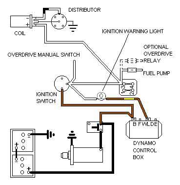
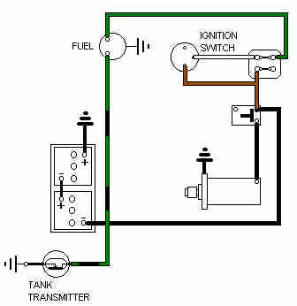
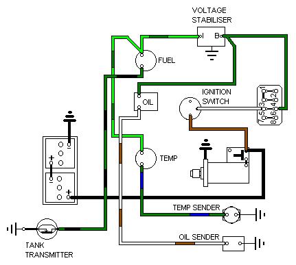
Schematics ![]()
Description
Problems
Electronic ignition
Testing October 2013
Internal and external seals
Description: There have been two types of electronic tachometers - the earlier RVI inductively-coupled type (which came in two versions - positive earth and negative earth) and the later RVC directly connected type. The inductively coupled type uses the white wire that goes from the ignition switch via the tach to the coil for triggering. The wire is looped round the tach pick-up and will only work the right way round. The RVC directly connected type was only used on negative earth cars and uses a black/white from the coil -ve (the same terminal as the points wire from the distributor) which terminates on a bullet-type connector at the tach rather than a flat spade. 1962-64 cars used a mechanical rev-counter.
Secured into the dash with two large 3BA knurled nuts 17H1304 and spring-washers, with a U-strap AJH5176 to September 64, separate 'legs' 17H3744 on each threaded stud from then until July 74, and 17H1339 after that until the 1977 model year.
 1977 and later have a much better arrangement where the tach and speedo have three studs in the instrument case, and by turning them clockwise 30 degrees these studs will align with cut-outs in the dashboard to allow the instrument to be withdrawn. Unfortunately LHD only.
The tach is powered from the white (unfused) ignition circuit on Mk1 cars, then for Mk2 cars onwards from one of two green (fused) circuits. Until 1978 this was the green circuit in the fusebox, but when the ignition relay circuit on RHD cars was modified sometime in 1978 and a second in-line fuse between brown/white and green wires was added under the fusebox, the tach is powered from one of these - the one with the thinner wires, the other with thick wires being for the cooling fan. For more information see the ignition schematics.
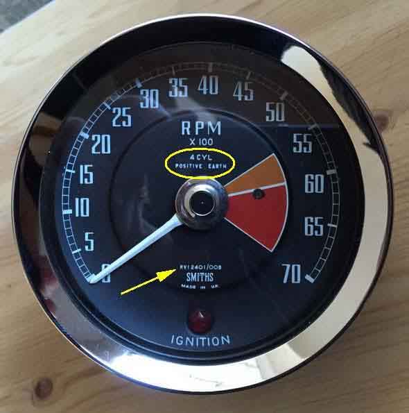 Tachometers were marked with the original polarity - positive and negative - from inception, at least until they changed from chrome bezels to plastic for the 1977 model year. But bear in mind that a PO may have changed the internal wiring of a positive earth tach and not changed the legend on the dial.
Serial numbers (on the faceplate) were as follows:
| Year | Chassis Nos. | Market | Battery Earth/Ground | Sensing | Pickup Location | Size | Reference No. |
| 1964-67 | 48766-138360 | All | Positive | Current | External | 4" | RVI/2401/00B |
| 1968 | 138401-153877 | Canada | Negative | Current | Internal | 80mm | RVI/2430/00 |
| 1968-71 | 138401-256646 | USA | Negative | Current | Internal | 80mm | RVI/1433/00 |
| 1968-71 | 153878-256646 | Canada | Negative | Current | Internal | 80mm | RVI/1433/00 |
| 1968-72 | 138401-294250 | Not North America | Negative | Current | Internal | 4" | RVI/2430/00 |
| 1972 | 258001-294250 | North America, Sweden, Germany | Negative | Current | Internal | 80mm | RVI/1439/00 |
| 1973-74 | 294521-360069 | not North America, Sweden, Germany | Negative | Voltage | N/A | 4" | RVC/2415/00AF |
| 1974.5-76 | 360301-409401 | not North America, Sweden, Germany | Negative | Voltage | N/A | 80mm | RVC/1410/00AF |
| 1973-76 | 294251-409401 | North America, Sweden, Germany | Negative | Voltage | N/A | 80mm | RVC/1410/00AR |
| 1977-80 | 410001-on | RHD | Negative | Voltage | N/A | 80mm | RVC/1414/00F |
| 1977-80 | 410001-on | LHD | Negative | Voltage | N/A | 4" | RVC/2432/00F |
| All | All | V8 | Negative | Voltage | N/A | 80mm | RVC/1810/00 |
Note 2: The change to 1968 Canadian models occurred part way through the year.
Note 3: There were gaps in chassis numbers. From November 1967 with the advent of the Mk2, most model years thereafter started at a 'round number' e.g. the last 1971 model was 256646 (a GT) and the first 72 model was 258001 (a roadster).
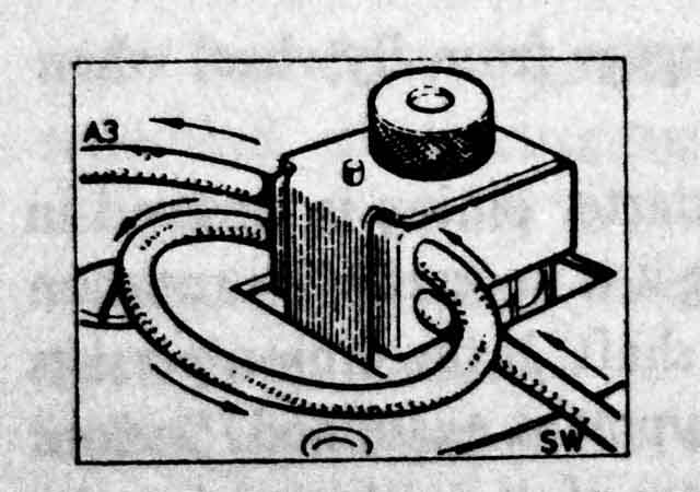 The RVI with external pickup either uses a white wire from the harness through the pickup, or may have a short section of white wire with bullet ends already in the pickup. In the former case there may be a long length (4 ft has been mentioned) of white coming out of the harness with a spade on the end, and this goes through the pickup then connects to an 'ignition on' spade on the ignition switch. This makes it easy to determine which way the wire has to go through the pickup. In the latter case the harness may have two separate whites with bullet ends, but it's an easy job to swap them over if at first the tach doesn't work. These tachs will only work with the current going through the pickup in one direction and you have to reverse it if you convert a positive-earth car to negative as well as reversing the 12v and earth connections. You will not harm the tach if the pickup is wired the wrong way round, but may do if the 12v supply is incorrect.
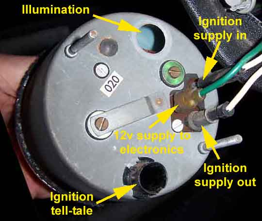 The RVI with internal pickup has male and female bullets on the back of the case, and corresponding bullets on two white wires from the harness. Note that these seem to be smaller than the standard wiring bullet and connectors at 4.5mm instead of 5mm (Malc Gilliver). The spade for the 12 supply to the tach electronics is close by the bullet connectors. The harness now has separate white wires with female and male respectively bullet connectors, meaning incorrect connection is not possible. Both RVI type tachs sense coil current and respond to the current pulses through the coil as the points open and close. If that circuit breaks the engine stops, if it shorts to earth you fry the harness! The earth wire for both the electronics and the instrument lighting is under one of the knurled wheels holding the tach into the dash.
See here for a description of the external pickup type from Mark Olsen's Sunbeam Tiger pages, and here for the later 2430/00 RVI with internal pickup by Herb Adler. However neither say much about the thermistor, this thread from The Sunbeam Owners Club of America states the original should have a value of 150 ohms at room temperature, but items in the 200 to 500 ohms should be able to be used successfully. A negative temperature coefficient (NTC) item is required, there are positive temperature coefficient (PTC) items around which are not suitable. Unfortunately suppliers in the UK only seem to stock items in the thousands of ohms, not hundreds of ohms.
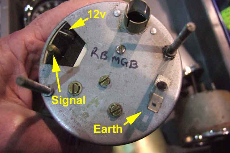 With the RVC voltage-operated type the ignition current does not go via the tach, instead a wire from coil -ve/points connection goes to the tach on a white/black wire, which responds to the voltage changes as the points open and close. If this circuit breaks the tach ceases to register and the engine continues to run. If it should happen to short to earth the engine will stop, but not fry the harness. (In fact this makes a nifty anti-theft device using a hidden normally open switch connected to the wire at the tach rather than in the engine compartment.) Since the current flowing through the coil has a direct relationship with the voltage at the coil CB or -ve terminal it follows that the two types indicate the same thing.
See here for information about the RVC tach by Herb Adler, Franz Hubl and Rick Astley.
Typical problems are sticking, wavering, or simply not working at all. Sticking, where a rap with a knuckle on the glass fixes it, and it only occurs after being parked for a while or at certain times of year, is almost certainly a mechanical problem with the movement itself.
Wavering or flicking about, if accompanied by changes in the idle speed, have a good chance of being caused by bad connections in the ignition LT circuit that is ignition switch - coil (via tach where appropriate) - points - earth.
Wavering or flicking about not accompanied by changes in idle speed, randomly dropping to zero for longer periods, or not working at all, could be either the 12v supply to the tach, the connection between coil and tach on the later voltage-operated types, or electronic problems inside the tach itself. From 64 to 67 the tach was powered from a third white (unfused ignition) wire and black earth but after that it was from a green (fused ignition) and black earth for both current- and voltage operated types. In no case is the tach powered from the instrument voltage stabiliser as the output from this is 12v switched on and off about once a second and so is unsuitable for the tach for obvious reasons. Get a multi-meter with an rpm range, connect it to the points-side of the coil, and compare that with the cars tach. If they shows similar variations then there is a problem in the ignition LT circuit through the ignition switch, coil and points. If it is steady when the cars varies, and you have the voltage operated tach, then connect the multi-meter to the white/black at the tach. Variation here but not before would indicate problems with the white/black wire or connections between tach and coil. If that is steady too, or if it was steady at the coil and you have a current-operated tach, monitor the 12v supply and earth at the tach. If these are steady too then the problem must be inside the tach itself.
If it works normally with the lights off, but doesn't work at all with them on, then the earth supply is probably missing. Early tachs have the earth connection as a tag under one of the knurled securing nuts (as on the other gauges). Later cars have a spade spot-welded to the back of the case, as well as the insulated 12v spade. A similar problem can affect headlights where relays have been installed when the speedo earth is missing and the main-beam tell-tale is in the speedo.
Very occasionally there are reports of the tach shooting up when the ignition is turned on but before the engine is started, or swinging right round to max with the engine running. About all you can do here is to unplug the illumination bulb and disconnect the trigger wire or wires, and see what happens with just the green 12v supply wire (white on Mk1 cars) and black wires connected. If you have 12v between the spade the green (or white) is connected to and the case, and zero volts between the case and a known good earth elsewhere on the car, and the tach is still registering incorrectly, then it is an internal problem. If it has suddenly happened it is quite likely to be a dry joint or cracked PCB track which may be visible, or a component fault which probably won't be. If you have less than 12v between the green (white) and the case, or any voltage at all between the case and a known good earth elsewhere, then the 12v supply or earth is faulty.
See here for information on companies that repair instruments.
There are several sites around showing how the original tach circuit can be replaced with one using a 555 timer - two examples here and here, and another example using a different IC here. All can be done to both RVI and RVC tachs, although in the first and third cases this would effectively convert an RVI to an RVC and would need a trigger wire from the coil CB or -ve instead of sensing the current pulses in the white wire going to the coil SW or +ve. Initial testing and calibration can be done using a basic battery charger as described here, then comparison with a separate instrument such as in a strobe light or automotive multi-meter which are likely more accessible.
July 2024: If you are not into building circuits there are also a couple of options to convert faulty RVI tachs to RVC using a pre-built circuit board from here and here which looks like the same module but cheaper for slower delivery. The modules may or may not fit into an RVC case.
This Easyfit module keeps the tach as an RVI avoiding wiring changes.
Electronic ignition: July 2011: If your RVI tach (64 to 72) doesn't work with your shiny new electronic ignition system, there are a couple of things you can try, depending on whether you have a positive earth car or a negative. Originally the 'fix' was to try changing the wire going through the pickup from two passes (one turn) to one pass (half a turn) and recalibrating. You will need to dismantle the tach to do that on later versions with the pickup coil inside. Subsequently Herb Adler reported that a 123 used with an RVI tach on a negative earth car (67 to 72) caused problems when following the instructions to connect the red (power) lead of the 123 to the Batt (+12v) terminal of the coil. He found that connecting this to an alternative 12v ignition source that didn't come through the tach pickup, e.g. the white at the fusebox, solved the problem. This shouldn't be necessary with the later RVC tachs, but is worth trying if you have other electronic ignition systems and tach problems. Note that this alternative connection is often recommended when putting electronic ignition on rubber bumper cars (i.e. with the ballasted ignition system), as the electronics are then fed with the full 12v and not the reduced and varying voltage.
Herb also reports that an RVI tach he had modified for 6-cylinders has R6 (see the above Tiger pages) at 820 ohms instead of 470 ohms.
Positive earth cars: June 2021
 Pertronix/Aldon positive earth Ignitors are wired completely differently to negative earth in that the Ignitor is in the 12v supply to the coil (SW) instead of replacing the points, and the points side of the coil (CB) is taken direct to earth. This means that the alternative source of 12v for the Ignitor to allow the tachometer to work correctly cannot be used, and Aldon for example say that the tach might have to be converted to the later RVC (which at the time of writing is an additional £42). But this Lotus Elan site suggests an additional wiring change which should - in theory! - work. That is to remove the existing white wire from the tach pickup and run a new black earth wire from the coil CB terminal round the tach pickup (in the same direction as the original white wire) and then to the tach earth.
Updated April 2012: In response to yet another complaint of an RVI tach not working with electronic ignition I dug out an old tachometer adapter that came with my Sparkrite ignition kit in the late 60s to see what it involved. It's no less than four transistors that basically provide a clean signal to drive the tach, probably together with powering the module from an alternative ignition supply. I no longer have the connection information for it but I suspect the adapter gets its input from the coil CB/Points terminal, has a second terminal going to earth, and the output terminal connects to the ignition feed via the tach. And whilst searching for information on connecting it I found these Sparkrite SX2000 instruction sheets. Steps 9 & 10 of the first one set and page 5 e) of the second basically say if you have problems with an RVI tach, the Sparkrite unit has two wires that would normally connect to the coil SW or +ve and you move the red one to an alternative ignition supply, i.e. basically the same thing, so worth trying first. 123 distributor, and the Pertronix, Aldon Ignitor and Powerspark under-cap modules are 3-wire systems that use a connection to each of the two coil spades and an earth from it's physical installation to the block or distributor, suggested wiring of these with the RVI tach is shown here.
July 2014: I suggested moving the red wire to new owner Bob Warwood, who had installed an Accuspark electronic ignition system, where the tach was reading about 800rpm high after installation ... but not if the lights were on! It seemed to me that he probably had a tach earthing problem, and with the lights on the voltage to the tach electronics was being reduced, and that overcame the problem caused by the electronic ignition. Bob reported that moving the red wire to the fusebox fixed the over-reading problem.
Testing: October 2013 I've always noticed my tachs give a little pulse of the needle if I turn the ignition on and off without starting the engine. I'd imagined this was from the trigger pulse as a 4-cylinder engine usually stops in one of two positions with the points closed, but a recent topic on the Yahoo MG-MGB list about this jump got me thinking. So I disconnected the coil and tried again, and still got the jump, therefore it's the power being disconnected from the tach electronics that causes the jump. If your tach suddenly stops working in the car turning the ignition on and off and looking for the jump as you turn it off would be the first test, which would indicate that the electronics were working - partially at least, and that the movement is working. It would also prove that the tach had the 12v and earth supply to the electronics. However both my tachs are the later voltage pulse triggered type with an RVC reference number on the dial, not the early current pulse type. A sample of one RVI tach is a little less clear. The first and second times the ignition was turned on and off the tach needle did jump, but on the third it did not. Neither did it jump when the white wire was disconnected from the coil and the ignition turned on and off again. On a subsequent test with the white wire disconnected the tach didn't jump, but when it was reconnected it did jump. As I say it's not clear yet, but the possibility is that the tach only jumps when the trigger circuit is complete i.e. the white is connected to the coil, so would be no help in diagnosing a non-functioning RVI tach.
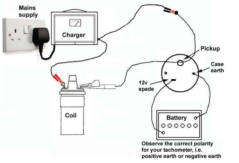 You can go further with a bench-test and a conventional battery charger (i.e. not one of the more modern conditioning chargers that are designed to be left connected to the battery long-term, I don't know what results these would give). For the earlier RVI-type tachometer connect the output of the charger to a coil or similar load, with one of the wires going through the tach pick-up in the appropriate direction to give the correct current pulse. Connect a 12v supply from a battery to the tach electronics via the usual insulated spade and case, observing the polarity of both the battery and your tachometer. With the charger switched on a 4-cylinder tach on 50 Hz in the UK (60Hz in the USA it seems, so in the remainder of this section figures in brackets refer to 60Hz mains supplies) should read 3000 (3600) rpm. I've not been able to confirm this as I don't have an early tach, but there are plenty of web sources indicating that this is the case. A 50 (60) Hz mains supply has 50 (60) positive pulses per second and the same number of negative pulses per second. If only the positive pulses are used (half-wave rectification), 50 (60) pulses per second, times 60 seconds, gives 3000 (3600) positive pulses per minute. A 4-stroke engine has two firing strokes per revolution so ordinarily you would have to divide that by two to get the expected reading on the tach, i.e. 1500 (1800) rpm. But most battery chargers should convert both positive and negative half-cycles of the AC supply to positive output pulses (full-wave rectification), which will give 100 (120) positive pulses per second, hence 100 (120) pulses times 60 seconds gives you 3000 (3600) rpm. If you have a charger with low and high settings, you might find that the low setting only has half-wave rectification, hence only 50 (60) positive pulses per second, and in this case you would see 1500 (1800) rpm on the tach.
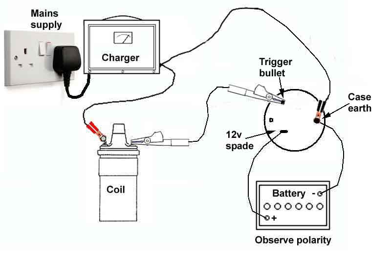 The later RVC-type tachometer can be tested in a similar way, but in this case the charger negative needs to be connected to the car body (in-car test) or the tachometer case (bench-test). Remove the wires from the coil +ve and connect the charger to the coil +ve. Disconnect the black/white from the distributor (25D4) or open the points. Turn on the ignition (in-car test) or connect 12v to the tachometer (bench-test) from a battery with +ve going to the insulated spade on the tach body and -ve to the tach case. With the charger switched on you should see the same tach reading as above i.e. 3000 (3600) rpm with a full-wave rectifier in the charger, or 1500 (1800) rpm with a half-wave rectifier. Note that unless the points are disconnected or opened the tach will not register. This test can be performed on rubber bumper cars with ballasted ignition and 6v coils as well as chrome bumper with unballasted ignition and 12v coils.
This test also gives you a very accurate way of checking the calibration of a tach. V6 engines have three firing strokes per revolution, so the V6 tachs readings would be 2000 (2400) rpm on full wave and 1000 (1200) rpm on half-wave. A V8 has four firing strokes per revolution, so those tachs would read 1500 (1800) rpm on full-wave, and 750 (900) on half-wave.
Early vs late systems
Later MGB system in an MGA?
Fault diagnosis
Tank sender
Voltage stabiliser
Calibration
Gauge identification
Internal and external seals
 Originally Jaeger gauge BHA4214E was used with a screwed tank sender, changing to Smiths BHA4470 in October 64 between chassis numbers 47112 and 48767 also with a screwed sender but electrically very different. In March 65 at chassis number 56742 the tank changed and the sender with it to one secured with a locking ring. This is the same electrically as the later screwed sender and Smiths gauges and continued to the end of production. Both these gauges have external night-time illumination with holes round the edge of the case to let the light in, and a fully exposed pointer. Mk2 cars changed to one with a partially shrouded pointer and internal illumination (BHA4736 or BHA4685 according to market with leaded fuel, BHA 5342 for the USA with unleaded fuel). All these have 'hanging' pointers, and use a sender with a locking ring. The final change was for the 77 model year and the plastic dash - to AAU3032 for leaded fuel and AAU3031 for USA unleaded fuel, with the indicator pointing upwards. The sender for these changed to one combined with the fuel outlet pipe, and as the North American electric temp gauge and sender both changed at the same time, and it is known mismatches between that sender and gauge cause incorrect readings, I had wondered if the same would apply to the fuel gauge and sender, but the resistances are very similar. All the gauges require an earth for night-time illumination, Jaeger and early Smiths (FG2530/70) gauges also need an earth for correct operation.
 Externally illuminated types are fixed in the dash with bracket AJH5185 which includes bulb holder, the rest with AJH5187. These fit over a central threaded stud and are secured with thumb nut 17H932 with spring washer WL700061.
Early vs late systems: July 2015:
Another difference between the two systems is that the early is 'fast-acting', i.e. it indicates the fuel level immediately you switch on the ignition. The later system is 'slow-acting' or damped and needs several seconds to indicate the true fuel level. The later system does have the benefit of not swinging about as the fuel sloshes around in the tank although that is usually reduced by the tank being baffled. However a drawback of the later system is that on a long bend such as on a motorway the fuel level will vary considerably between a left and a right, and take time to settle again once you have straightened up.
A further difference between Jaeger and Smiths systems is that whilst on both the tank sender is a variable resistance that changes as the fuel level goes up and down, on the early system the resistance is high (about 70 ohms) when the tank is full, and low (close to zero) when the tank is empty. On the later system the resistance is lowest when the tank is full increasing as the tank empties, varying between 20 and 240 ohms according to information from the gauge manufacturer Caerbont.
A third difference is that on the early gauge the wires must be connected to the correct terminals, but on the later gauge can be connected either way round. The early gauge has one terminal marked 'B' - for Battery, the green wire goes on this. This terminal is on the upper right part of the back of the gauge, and usually has two spades, so you can use it as a pick-up point for a fused ignition supply for something else. The other terminal is marked 'T' - for Tank, the green/black wire goes here, and is in the upper left area of the back of the gauge.
A quick test of the early system is to disconnect the green/black sender wire from the back of the gauge, and the gauge should register above F. Earthing the sender terminal should cause the gauge to read Empty or just below. Connecting a 70 ohm resistor to the T terminal (tank wire disconnected) should cause it to read close to Full, and a 35 ohm resistance should cause it to read slightly below half. For further information on the early system see Barney Gaylord's web site, the remainder of this section largely relates to the later system.
From the above it should be obvious that a late sender with an early gauge will not work correctly, nor vice-versa. The correct tanks, senders and gauges are normally available with one exception, and that is for the brief period where the tank still used the screwed sender, but electrically used the later system. This sender is NLA so would normally mean you had to use an early Jaeger gauge, or change the tank to the later type with the locking ring. See here for an alternative to either of those.
Later MGB system in an MGA?: December 2023:
That contains a link to Classic Bits for the parts but you still have to browse all the products and pick the correct one. The MGB item uses the locking ring not the screws and even though there is an MGB screwed sender for a bi-metal gauge available elsewhere it has a different part number and may not work correctly in the MGA tank. The correct item for the MGA to be used in conjunction with the a bi-metal gauge is also listed but quotes the original part number AHH5114 which is for the magnetic system i.e. using the original gauge. It also quotes Smiths number TB1114-031W and if you Google that you will get loads of hits for BL part number AAU8340 including for the MGA Twin Cam (!) and classic Mini van and estate. Prices for those can vary from £18 to £70 so it pays to shop around. As said in the article and in the Classic Bits detail this sender will only work with the later bi-metal gauges and needs the MGB instrument voltage stabiliser as well. That makes them suitable if you have to replace your MGA Jaeger gauge, but if that is still functioning you need the original AHH5114 sender, which has a completely different physical appearance to the one for bi-metal/thermal gauges.
Looking at the gauges themselves some suppliers (MGOC and Traditional Old Motor Spares/Ron Leacy) show a Jaeger gauge 17H299 FG2530-05 for 1500cc MGAs from chassis 14090 and 1600s as well as Twin-cams which is described as 'bi-metal' whereas Moss Europe gives the same model info but doesn't say it is bi-metal, others indicate that part number is for the twin-cam only. None seem to list the voltage stabiliser for any MGA and all state gauge AHH5189 for other models which needs the earlier sender and no stabiliser. Speaking to Caerbont who manufacture the gauges they say they haven't made the magnetic gauges since the 60s so all new stock at suppliers will be thermal even though they use the same part number FG2530-05, they are going to clarify their web page to include information on the sender and stabiliser. They already show the BF2300-02 gauge for the MGB as 'bi-metal resistance'. FG2530-05 would be suitable to replace the MGB Jaeger gauge used up to October 64, but would need a different sender to that for the MGA, and a voltage stabiliser.
The stabiliser has its own complications as those available today all seem to be electronic and are polarity sensitive with different versions for +ve earth (128484) and -ve earth (BHA4602). The originals were thermal like the gauges and neither are polarity-sensitive.
Confusing!
Diagnosis of the later Smiths system:
Non- or erratic operation:
Briefly connect an earth to the terminal with the green/black wire on the back of the gauge. Does the gauge pointer move smartly towards to 'Full' (remove the earth as soon as you see the pointer moving)?
| | No - check for voltage on the light-green/green wire of the gauge. Is it present?
| | | No - check the same wire on the stabiliser. Is voltage present?
| | | | No - check the green wire on the stabiliser. Is 12v present?
| | | | | No - check the green circuit back to the second fuse up in the fuse block.
| | | | | Yes - looks like the stabiliser is faulty, but could be a partial short to earth in the gauge or stabiliser to gauge wire. Remove the light-green/green wire from the gauge, is the voltage on the output of the stabiliser now correct?
| | | | | | Yes, measure the resistance of the gauge and it should be about 61.5 ohms between the terminals, and neither terminal should show a resistance to the case. If the resistance is low or there is circuit to the case the gauge is faulty.
| | | | | | No, remove the light-green/green wire from the output of the stabiliser, is the voltage there now correct?
| | | | | | | Yes, light-green/green wire shorting to earth.
| | | | | | | No, stabiliser faulty.
| | | | Yes, light-green/green wire from stabiliser to gauge open-circuit.
| | | Yes, is it steady 12v, 12v switching on and off about once per second, or steady 10v?
| | | | Steady 12v (incorrect) - check the earthing of the metal can of the stabiliser, if that is OK it looks like the stabiliser is faulty (giving high readings).
| | | | 12v switching on and off about once per second or steady 10v (correct) - looks like the gauge is faulty. With the ignition off and at lest one wire removed from the gauge measure the resistance between the gauge terminals, it should be about 61.5 ohms
| | Yes - briefly earth the green/black wire at the tank unit. Does the gauge pointer move smartly towards 'Full' (remove the earth as soon as you see the pointer moving)?
| | | No - disconnection in green/black wire back towards the gauge, check the bullet connector between the main harness and the rear harness in the mass by the RHD master cylinders.
| | | Yes - with the green/black wire on the insulated terminal of the tank unit connect an earth to the base-plate of the tank unit. Does the pointer move?
| | | | No - looks like the tank unit has failed.
| | | | Yes - bad connection back towards the main earthing point on the back panel of the boot (CB cars) or between sender and tank or tank and body (RB cars).
| | |||||||||||||||||||||||||||||||||||||||||||||||||||||||||||||||||||||||||||||||||
Even if you see pulsing 12v (or steady 10v) on the green/black when disconnected from the sender showing there is continuity back through the gauge and stabiliser, it could still be high-resistance from a bad connection. When connected the voltage on the green/black wire between the gauge and the sender will show a voltage that is inversely proportional to the amount of fuel in the tank. With a full tank it will show a low voltage, and as the tank empties the voltage rises. With a full tank and original factory stabiliser I have 2.7v on the green/black, but that's while the stabiliser is still outputting steady 12v i.e. for the short period after turning on the ignition, with the engine not yet started. It would be a bit higher with the engine running and the alternator charging. After that the voltage switches on and off and is more difficult to determine, so you need everything connected and have the meter fairly visible before you switch on the ignition. Once it starts switching on and off you would have to leave the ignition off for a few minutes to 'cool down' before turning on will display a steady voltage for several seconds again. The aftermarket stabiliser that outputs 10v all the time is easier - on a full tank I'd expect that to show ten twelfths of 2.7v, i.e. about 2.25v, so not that different, and all the time even with the engine running. Much lower in either case indicates bad connections, which could be bad enough to stop the gauge moving at all, but still show 12v on a voltmeter when the wire is removed from the sender. Both my gauges measure 61.5 ohms +- a tenth or so, with just under half a tank in the roadster I measured 90mA in the circuit and in the V8 with a full tank (bar a few miles) with a nominal 12v I get 140mA. Both cars have the original thermal stabilisers and the currents were measured when the stabilisers were outputting full ignition voltage for the few seconds after switch-on, i.e. before they have started switching 12v on and off about once per second. With an electronic stabiliser outputting about 10v immediately I'd expect to see about 70mA with half a tank and 120mA with a full tank.
Tank Sender: Updated December 2015
Wiring
Replacement
Later MGB system in an MGA?
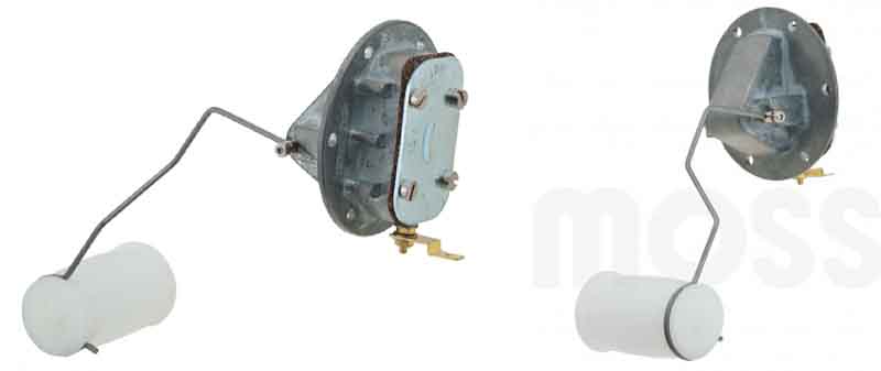 Early cars up to October 64 had sender BHA4292 attached to tank ARH176 with six screws, and was for the unstabilised 'magnetic' Jaeger gauge BHA4214E. Note that new stock gauges use the later bi-metal system with a different tank sender and requiring a voltage stabiliser.
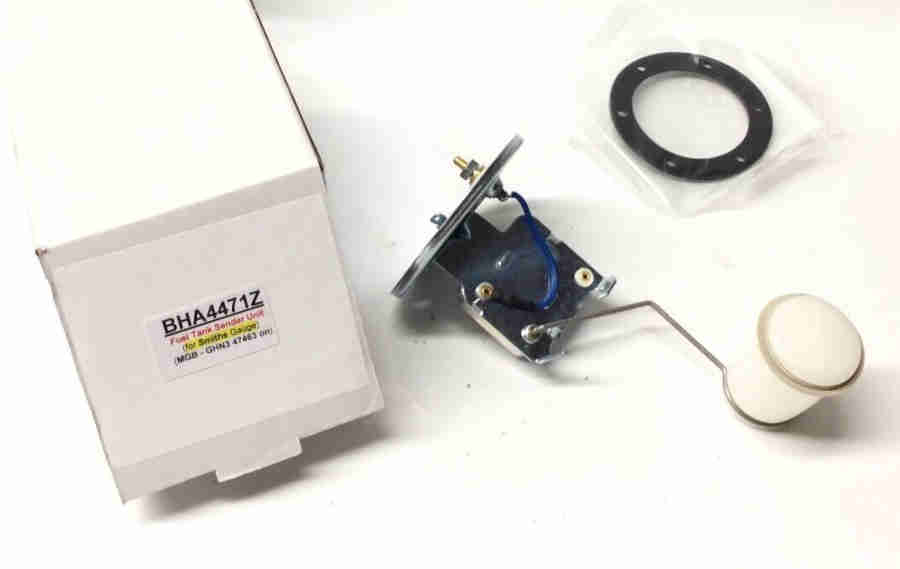 A stabilised system was then introduced over a period from chassis number 47112 to 48767 in October 1964 using sender BHA4471E also secured with six screws and operated Smiths bi-metal gauge BHA4381E with the same exposed pointer and external illumination as the Jaeger gauge. However the two systems are not electrically compatible and the matching sender and gauge have to be used or pointer movement will be reversed and wildly inaccurate. Because the tank and sender changed in March 65 sender BHA4471E was only used for a few months and was NLA for decades, available again now.
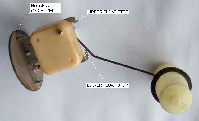 At chassis number 56742 in March 65 the tank was changed (variously ARH223, NRP2 or NRP1132) and secured sender ARA966 with a locking ring which works correctly with the Smiths gauge.
On rubber bumper cars prior to August 76 the harness earth wire for the sender was deleted which previously went back to a number-plate bolt in the boot (also used for reversing lights and fuel pump) and the spade left unused. The sender then got its earth from its physical mounting to the tank and the tank mounting to the body. That only works for the original metal-base sender, current stock are plastic so for rubber bumper cars an earth connection needs to be provided from somewhere reliable. However the Workshop Manual North American diagrams for 1972 with seat belt warning onwards no longer show this earth wire so it may have happened to those cars earlier. On the other hand the UK 74 1/2 to 76 diagram still shows it, but going by my 75 it had gone by then. Note that restoration with good paint coverage may prevent the sender from 'seeing' an earth from the body, mine has a PO earth wire from the earth spade on the sender to a body bolt.
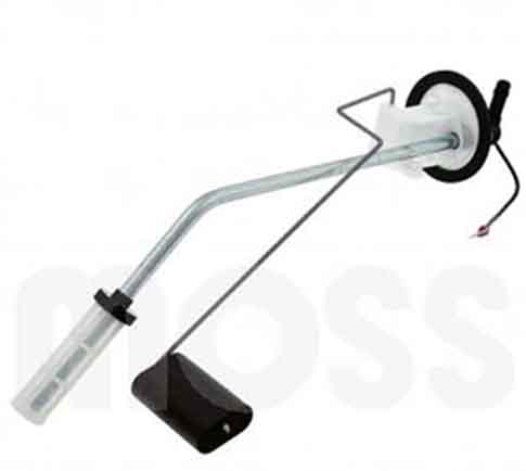 The final change (physical only, electrically the same as before) was shortly after the start of the 77 model year in August 76 when the sender was changed to include the pick-up tube, still fitted with the locking ring.
January 2023:
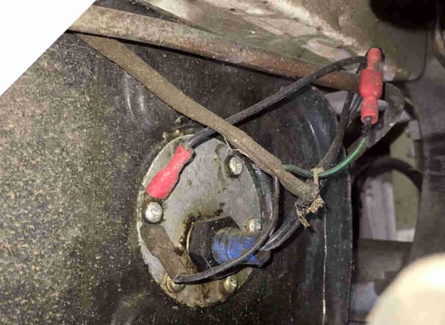 Helping Geoff Taylor reinstate a fuel gauge on his car (a PO had replaced it with a voltmeter!), it would originally have had a Jaeger gauge and the early screwed sender but he didn't get the gauge with the car. Jaeger gauges are hugely expensive even when available so he had obtained a Smiths gauge, but having the early screwed-sender tank needed the NLA sender! The sender on his car had a very different external appearance to any I had seen and didn't exhibit a resistance, so was an unknown quantity and needed to be replaced. Having looked on previous occasions and found nothing this time I found a relatively recently re-manufactured item from Bastuck in Germany for 75 Euros. One inconsistency in the information on this sender is that they say 'MGB AFTER GHN3 47463 (1962-65)'. The chassis number is broadly correct in that it falls into the range given by Clausager for this change of 47112 to 48764 but those chassis numbers all fall within October 1964 and so the date information should read '1964-65'. Subsequently Geoff found this one in the UK from jmccspares which seems almost identical giving the right part number and stating it is for the Smiths gauge. It came in the same box as the Bastuck one so must have originally come from there, but that eBay ad now says 'listing ended' so maybe jmccspares only ever purchased the one.
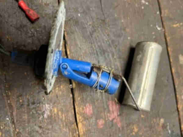 When Geoff removed the existing sender it turned out to be of a type I had never seen before. Possibly a magnetic proximity system as part of an oscillator circuit so even more different than the Jaeger and Smiths systems are to each other, and maybe why there was a voltmeter on the dash.
As the sender and the gauge changed in 1977 at the same time as the temp gauge and sender on North American spec, and if you get those mismatched the readings are incorrect, and I had wondered whether the same applied to the fuel. This was after reading about someone who had been getting strange reading with a late tank and sender and the earlier gauge, but it turned out his sender was at fault cutting out part-way through the range (as my four failures on two cars had been). A replacement OE (i.e. metal) late sender with output pipe measured 20 to 258 ohms before fitting (Colin Tozer), and an after-market plastic without outlet pipe measured 17.5 ohms to 250 (John Holland), although since then two people have posted that their pre-77 plastic ranges between 6 and 250 ohms. Vee's measures 25 ohms with a full tank and Bee's 22 ohms - both OE metal types. Colin was concerned that his late tank with earlier gauge would read incorrectly, but given those figures this seems unlikely. Info from Caerbont the manufacturer of the gauges is that they operate from 240 ohms empty to 20 ohms full.
November 2019: Colin Parkinson has received a plastic sender from Moss and has measured it at 18 to 185 ohms, so hugely different to the others at the 'empty' end and seemingly (bearing in mind all the above measurements were taken by different people with different meters) as much variation from one sender to another as the earlier metal-base type. This could well result in showing a couple of gallons left when it runs out.
February 2020: As well as the significant variation in readings from plastic senders someone on a forum elsewhere returned a plastic sender to the MGOC saying it was way out, and the response was inevitably "not had any problems on the other 2000 we have sold.... ". Then later on they said they had had a faulty batch!
The thermal system uses voltage to drive a current through a heating element to move the pointer and the ratio of resistance change to pointer movement is very non-linear. The OE sender attempts to compensate for this by varying the shape of the former of the wire-wound resistance, and the number of turns per mm encountered, as the wiper moves across the resistance but as can be seen from non-linear gauge markings it's only a partial success. Even with all that the indication still doesn't match the contents across the range, once mine get below half it is noticeable how quickly they move across towards one quarter, which has given me a moments panic on more than one occasion.
 Bizarrely plotting resistance and voltage against gauge calibration marks showed that the voltage was linear with the gauge markings, but the resistances weren't. How can that be, Mr Ohm? The resistance wire used in the gauge to heat a bi-metal strip to move the pointer has a positive temperature coefficient i.e. the hotter it gets the higher its resistance goes, and there is also the changing force needed to bend the bi-metal strip along its range of movement, and the system of levers that causes the pointer to move.
What follows relates to the later Smiths system, for the earlier Jaeger system see here.
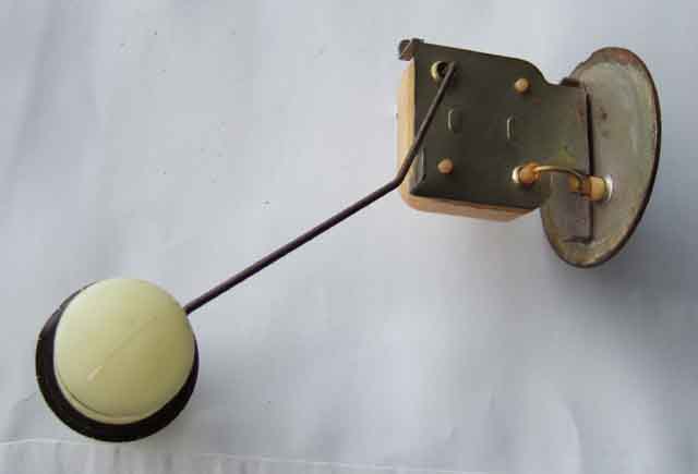 The sender consists of a length of fine wire wrapped round a former - one end is connected to the insulated terminal on the 'base plate' of the tank unit and the other end is open circuit. As the fuel level rises and falls a float an arm moves an earthed 'wiper' contact across the wrapped fine wire, making a variable resistance The wiper contact is connected to the body of the base plate via the float arm and its pivot in the sender structure. The wound former is tapered in shape and the distance between adjacent turns varies along it in an attempt to make the movement of the gauge indication bear some relationship with the quantity of fuel in the tank ... but it's not very good. On my two cars I get infinite MPG for the first 40 miles, 50-odd MPG for the first half of the tank, about 10mpg from half to a quarter, and something a bit closer to the actual mpg for the bottom quarter. The resistance range is from about 20 ohms for 'Full' to about 250 ohms for 'Empty', although there seems to be quite a bit of variation between tank units and changing them has caused significant variation in gauge readings, see the section on calibrating the gauge.
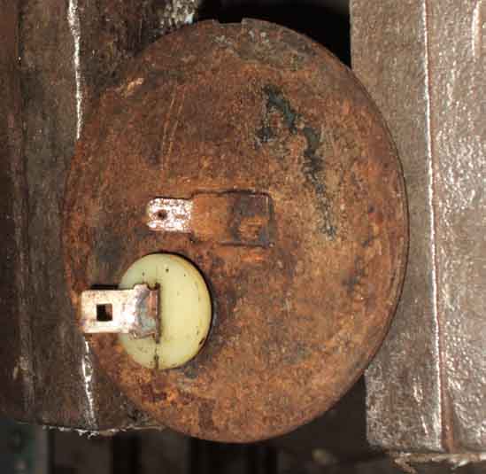 Up to September 76 the sender base-plate has two spade terminals - an insulated one to which the green/black wire goes and a smaller, uninsulated one which should have an earth wire on it, which usually goes to the earthing point at the number plate bolt on the boot rear panel together with things like reversing lights and fuel pump. It is possible for the fuel gauge to work without this earth wire but only via several non-electrical metal-to-metal contacts which can be unreliable. From September 76 senders with the integral outlet pipe did not have the earth tag, so does rely on the mechanical fixings of the tank.
David Jackson wrote to me with a problem he was having with a new Heritage tank ARH176 with the screwed sender for the early Smiths stabilised gauge. When fitting the original sender it seems to foul something internally and does not freely move up and down from Empty to Full. This sender float moves in a different arc to both the Jaeger and the later locking-ring senders, as shown here. He has had to fit the earlier Jaeger sender, but the unstabilised system works in reverse to the stabilised system i.e. Empty is low resistance and Full is high resistance, whereas for the stabilised system Empty is high resistance and Full is low resistance. The upshot is that his gauge was working in reverse. However he found this Spiyda module that as well as allowing calibration of E and F, also reverses the operation to correct the indication on the gauge.
For details of tanks, senders and gauges see here.
Sender wiring: December 2020
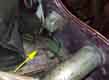 CB cars have the 2-wire tail for the sender splitting away from the rear harness in the boot by the off-side light cluster, going out through a hole by the bumper iron, then travelling forwards clipped to the edge of the tank to the sender. It might seem a bit odd to run the sender wires right to the back then forward to the sender, but as the earth wire has to come back to the rear panel it's as broad as it is long. Note that the Leyland diagram for North American 1972 models with seat-belt warning show the sender earthing to the tank and not via an earth wire.
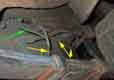 RB cars have the tail leaving the rear harness by the fuel pump and going above the axle back towards the sender. Prior to 1977 and the change in sender the RHD wiring diagrams show this as being two wires as before - the gauge wire and an earth. However on my 1975 V8 and an American pal's 76 there is only one sleeved wire coming from the harness, which the Parts Catalogue seems to confirm as the rear harness did change part number on all models for rubber bumpers, and without the earth wire it makes sense for the tail to split off sooner rather than go all the way to the back then have to come forwards again. The difference between us is that whereas his earth spade on the sender is unused mine has a local earth wire on it - so almost certainly a PO bodge, perhaps if a replacement tank was too well painted and undersealed and failed to pick up an earth. In which case perhaps that earth is failing and causing the erratic readings after refuelling that I have noticed recently.
1977 and later have a combined pickup pipe and sender with just one connection for the gauge wire, no provision for an earth wire i.e. the earth is picked up by the sender body from the tank and the car body through mechanical fixings. This means that when fitting a plastic-bodied sender an earth wire has to be provided or the fuel gauge will not work.
Replacing the sender:
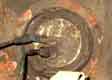 The sender can be replaced with up to about a 1/4 tank of petrol in the tank if you raise the right-hand rear corner of the car. Early cars had the sender screwed into the tank with a thin cork gasket, from about 1964 it is held in place with a locking ring that locates under three lugs on the tank and uses a thicker rubber gasket. The locking ring consists of three tapered sections that locate under the lugs and as the locking ring is rotated in a clockwise direction the tapers cause the tank unit to be pressed in towards the tank making a seal. To remove the tank unit rotate the locking ring in an anti-clockwise direction, having come across a picture of the factory tool after many years I made my own. But by alternately tapping on the thin end of a couple of the tapered sections of the locking ring with a hammer and drift you can achieve the same effect. The use of steel tools is usually quite safe unless the area is wet with petrol.
Check the new tank unit by connecting it up to the green/black and earth wires and checking the movement of the gauge pointer as you move the float up and down on the tank unit. And before paying for it make sure it makes a smooth and quiet transition from Full to Empty and back again. If the movement is at all 'scratchy' reject it as a sharp edge on the wiper is probably catching on the turns of the resistance wire and will break them in a relatively short time.
Install the new tank unit by putting a new rubber sealing ring against the tank, then the sender unit on top of the seal, and finally the locking ring on top of the sender unit, rotating it in a clockwise direction to tighten it.
A new tank or tank unit will often throw the gauge 'accuracy' out, check the 'empty' indication and readjust as soon as possible (personal experience!)
January 2015:
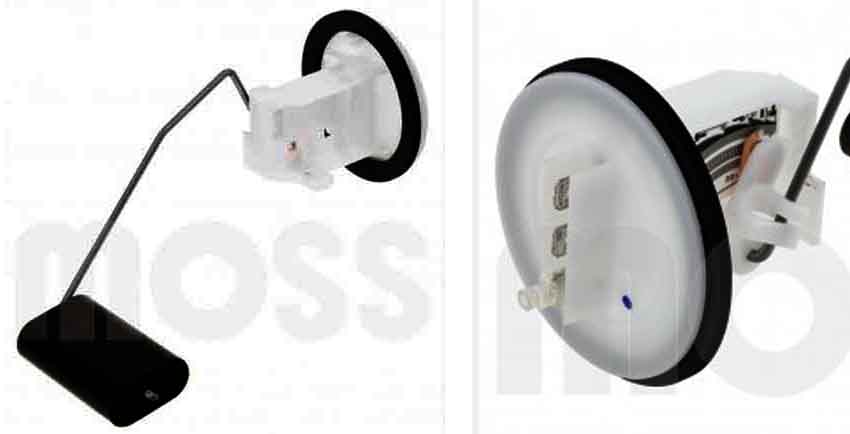 It seems that the original senders with the metal base and installed using the locking ring (ARA966, 11H5062) are no longer available and suppliers only have the later 'ceramic resistor' type which have a plastic base (AHU1027 for up to August 76, ADU3218 after that with the integral pick-up pipe) in the UK at last as Moss.com show both types. The plastic type come with three terminals, the additional one being for a 'low fuel level' warning which the MGB does not have. If the wiring is not connected to the correct terminals the gauge will not work properly, so test the sender through it's full range and check the gauge responds accordingly before installing it. Note that whereas the original pre-77 senders have an under-sized spade for the earth wire, these replacements seem to have standard-sized spades for all three, so the wiring connector will need to be replaced or an adapter made up. However 77 and later cars do not have an earth wire to the sender i.e. there is only one wire from the harness, so you will need to provide an earth wire as the sender won't be able to pick up an earth from the tank. Senders from Moss at least are shown as being provided with this earth wire, other vendors may not include it.
Herb Adler's experiences with tank senders.
Voltage Stabiliser: Updated July 2013
Where is it?
Is my stabiliser working?
The purpose of the instrument voltage stabiliser is to supply a 'constant' (but see here) voltage to the instruments so that the only variation in readings comes from the senders, and not from changes in supply voltage, which can vary between 12v and 15v.
Note that MGBs up to October 64 with 18G and GA 3-bearing engines and Jaeger instruments did not have a stabiliser as the fuel gauge used a different method of compensation for supply voltage variations, see Barney Gaylord's MGA site.
Also note that the tachometer is fed with the standard system voltage not the stabilised voltage, schematics that show the tach feed coming off the stabiliser are simply using the stabiliser as a tee-ing point for the fused ignition supply. The diagrams do show that the North American electric oil gauge used from the start of Mk2 production was fed from the stabiliser, but only for the first year after which it was also fed with full system voltage. This is almost certainly an error in the drawing as the gauge and sender did not change after one year, and the electric sender is of a type used on other makes and models which has its own method of stabilisation as well as indicating pressure. In any event the electric gauge reverted to mechanical with a capillary tube for the 1971 model year on.
Further note that when buying a stabiliser today they will almost certainly be electronic and not the original thermal unit, and as such are polarity sensitive. The thermal units are not polarity sensitive and were use on both positive earth and negative earth cars, more info here.
'Stabiliser', when applied to the original component, seems an inappropriate term. With the original stabiliser when first turning on the ignition you will see system voltage i.e. nominally 12v on both the 'B' and 'I' terminals for several seconds, then the 'I' terminal will start switching between system voltage and 0v once or twice per second - the relative lengths of the 'on' and 'off' periods changing as the system voltage changes. As the system voltage rises the 'on' period gets shorter, and as the system voltage falls it gets longer, the length of the 'off' period is relatively constant. The effect is that over time the average voltage to the gauges is kept at about 10v and they give a stable reading determined solely by the sender resistance, and not by changing system voltage. Since the gauges are thermal instruments (the current flowing through a coil heats up a bi-metallic strip which bends and moves a pointer) they are slow to move large distances and so the relatively short on and off periods don't allow the pointer to move very much at all. But if you watch a gauge carefully, when it is showing about 1/2 a tank or normal engine temperature, with the ignition on but the engine off, you can sometimes see the very small movements up and down as the stabiliser switches on and off.
The stabiliser consists of a bi-metallic strip with its fixed end connected to the I(instruments) terminal i.e. to the gauge(s), and its moving end breaks and makes contact with the B(attery) terminal i.e. the 12v supply. A heating element is wound round the bi-metal strip and connected between it and earth i.e. the case. With the bi-metal strip cold the contact is closed, so system voltage is passed to the gauges and flows through the heating element to earth. The heating element causes the bi-metal strip to bend, which opens the contact, which disconnects system voltage from the gauges. It also disconnects system voltage from the heating element, so the bi-metal strip cools, closes the contact again, which reconnects system voltage to the gauge(s) and the heating element, and the cycle is repeated all the time the ignition is on. With high system voltages the heating current is higher, which causes the bi-metal strip to bend faster, and open the contact sooner. However it cools at a relatively constant rate, so the contact takes about the same time to close again regardless of system voltage, which is how high system voltages result in shorter 'on' times than low system voltages. A kind of pulse-width modulation, if you want to get technical.
You may wonder about the effects of ambient temperature changes on the bimetal strip in the stabiliser, and indeed the gauges, as they could be fitted to cars operating in temperatures from well below freezing to above 45C/115F. Some have said the ambient changes are much less than the changes due to the heating coil, but even if they were only 10% of the change, a range of 55C/100F in ambient would need the heating coil to be operating at ten times that i.e. 550C/1000F which is ridiculous. Instead the stabiliser and gauges are designed to ignore ambient temperature changes, as described here.
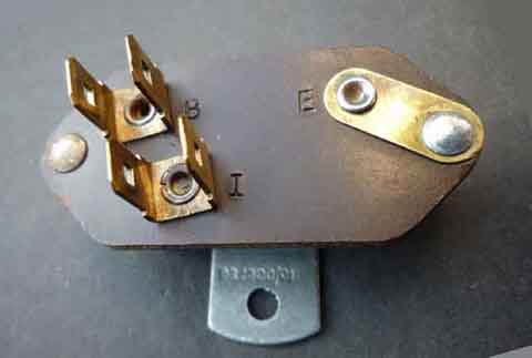 The stabiliser has two terminals - B(attery) and I(Instruments), and its 'can' needs to be properly earthed (usually screwed to the firewall behind the dash on the RHS of RHD cars for example) for it to work correctly. Because the original factory stabiliser has moving parts inside it also needs to be mounted the right way up, as indicated by the 'TOP' and arrow markings on various versions. The green wire goes to the B terminal and the light-green/green to the I terminal. The stabiliser changed from Mk1 to Mk2 cars, it looks like Mk1 cars had a stabiliser (12H 7819) with two male spades on each terminal, so it is possible to get the wiring the wrong way round. Mk2 stabilisers (BHA 4602) have male spades on the 'B' terminal and female on the 'I', so it should not be possible to connect the wiring incorrectly. Because each terminal has two spades the unused male spade on the 'B' terminal can be used as a source for a fused ignition supply to an accessory if required. Don't use the 'I' terminal. On original Mk2 stabilisers there is also a threaded adjuster stud for calibration, but remember that with two or more electric gauges altering this will affect all the gauges. If only one gauge is reading incorrectly, because of a replaced fuel tank sender for example, you should recalibrate the gauge, not alter the voltage stabiliser. The position of the stabiliser moved from low down on the firewall behind the dash in front of the (RHD) driver on earlier cars (e.g. Mk1), to hidden away right at the top above the wiper motor, and much more difficult to get at on my 73 roadster. It moved back down again on my 75 V8, and now the indicator and hazard flashers were hidden away. Later on both flasher units may have moved to that position and the stabiliser hidden away again!
January 2020:
 As far as the 'TOP' marking goes, I was surprised at just how much difference the orientation of the original stabiliser makes to the fuel gauge reading (should make no difference with the electronic replacement).
Updated July 2010:
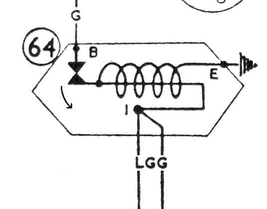 Incidentally the drawing in the Leyland Workshop Manual is misleading, as shown it couldn't possibly work! The contacts by the B terminal should be shown closed, as this is how they are when first turning on the ignition, to pass current through the winding to heat the bi-metal strip and pass voltage through to the gauges, as shown in this amended drawing. It is only when this has heated up and the moving contact bends away from the fixed contact that voltage is disconnected from the heating coil and the gauges.
Some (Many? All?) suppliers only have electronic stabilisers available, and these are often polarity sensitive e.g. Moss 128484 for positive earth cars, and BHA4602 for negative earth, so you have to get the correct type. However Moss state the earlier one is for 62 to 67, which is incorrect, MGBs didn't get the stabilised system until 1964. Ironically if you installed an electronic stabiliser to the early cars it probably wouldn't make any difference, but if you connected an original the fuel gauge would go up and down about once per second! Incidentally Moss are naughty as they have retained the original part numbers even though it is not an original component. These stabilisers don't have the adjuster stud. Brown and Gammons (Mk1, Mk2 on showing the correct spades in each case) have also used the original part numbers and also implies the early ones were used from the beginning. Their Mk2 stabiliser at least has the 'TOP' markings, which implies it is the original thermal device. But from what I can see they don't have the adjuster studs, so almost certainly electronic as well (and equally naughty). Googling I can't find any pictures that show the adjuster stud, so maybe they are all electronic these days (you can certainly see the printed circuit tracks in many images). Many of those are labelled 'NEG' or 'POS' indicating they are polarity sensitive, so you must get the correct polarity, as well as one with the correct spades for your wiring. The Moss and B&G items don't show polarity, but the early one will be positive earth and the later negative, so unless they are polarity independent the early one wouldn't work on an early car that had been converted to negative earth.
Some people are tempted to replace the original stabiliser with an electronic one, thinking it must be better. In fact they are not so good, as they output 10v as soon as the ignition is switched on, whereas the factory stabiliser outputs full battery voltage for several seconds, resulting in a faster gauge rise time.
There are also claims that the thermal stabiliser output varies 'a lot' with changing ambient temperature but that's not correct. The gauge also being bi-metal/thermal would also be affected by ambient temperature, and whilst the bi-metal stabiliser would cancel it out when fitting an electronic stabiliser that would no longer be the case and the gauge on its own would vary 'a lot'. But it's more sophisticated than that. Both stabiliser and gauge have a U-shaped bi-metal strip with only one leg of the U being wound with heating wire. With the U being mounted at the end of one leg and the end of the other leg performing the switching (stabiliser) and pointer movement (gauge) it follows that both legs will bend by the same amount at varying temperatures so neither the switching not the pointer movement are affected. It's only when the heating winding adds additional heat to it's leg of the U that one leg will bend more than the other.
Herb Adler describes how he made his own electronic version.
Where is it?
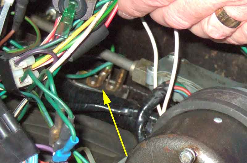 On my 73 it is high up on the firewall, behind where the wiper rack comes out of the motor and as such rather inaccessible. On later models (such as my 75 V8) it is on a tab on the lower edge of the bulkhead below the wiper motor and much easier to get at. However it seems that on 77 and later it moved back up to the earlier position even though the tab is still there and unused. A pal's 78 has it on that tab but it looks like a replacement unit secured with a nut and screw so probably replaced and fitted there for convenience! LHD cars have it on the other side of the car by the instruments.
Is my stabiliser working?
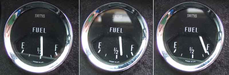 A quick way to check is to see what your fuel gauge registers about 30 secs after turning on the ignition but not starting the engine, and comparing that with what it registers when the engine is running - you do need to have some space in the tank i.e. the gauge not registering Full. There should be no difference, but if your stabiliser is not regulating the voltage it will read significantly higher when the engine is running ... always assuming your charging system is working correctly of course!
 You can use a voltmeter for a simple go/no go test of the stabiliser i.e. is it putting out a constant 12v? Or no voltage? Both of which indicate faults. But if your OEM stabiliser is pulsing (as it should) but outputting a higher or lower average than it should and hence causing the gauges to read higher or lower than they should, things are a bit more tricky.
 If the 'ons' and 'offs' are short enough (they can vary quite a bit between stabilisers) you can gauge an analogue meter by eye, but a digital meter will probably be flicking about all over the place. But you can make a test-rig, as shown here. With this you will get a slow rise in voltage on the meter, towards battery voltage, until the stabiliser starts pulsing, then it should stabilise (oddly enough ...) at about 10v, which should be good enough for a steady reading on a digital meter.
Note: January 2023 The above relates to the original thermal stabiliser, electronic ones should put out a steady 10v on the 'I' terminal as soon as you turn on the ignition and do so whether the gauge and sender are connected to the circuit or not. When they are connected it may drop by a couple of tenths or so.
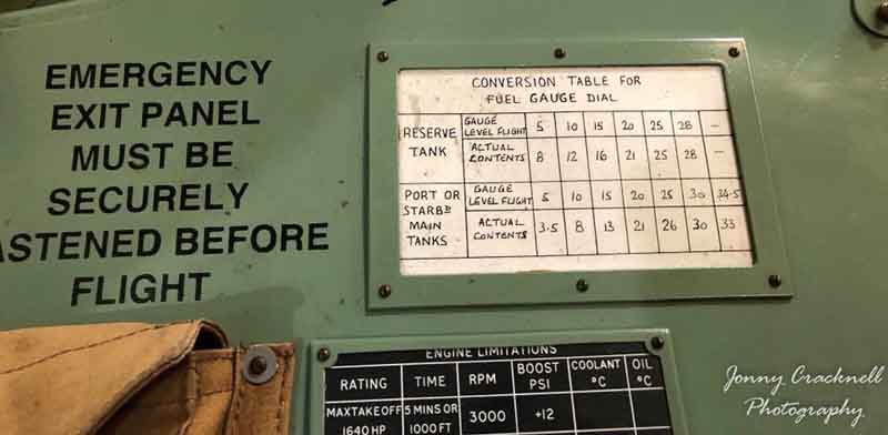
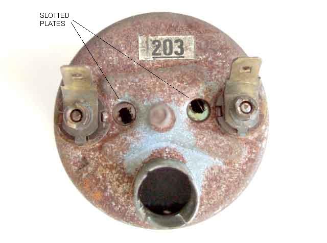 Whilst it is possible to bend the upper and lower stops on the sender to get a bit more travel (but run the risk of running off the end of the winding at either or both ends), or bend the float arm (which only moves the available travel up or down the range of the gauge to leave an even bigger 'dead area' at one end or the other), the real problem is when the resistance doesn't go low enough at F or high enough at E to get full travel of the gauge needle, so the only real solution is to alter the gauge to compensate for this. Getting at the gauge is also a lot easier (except for 77 and later) than getting at the sender, can be done at any time i.e. with a full tank, and you won't get leaks afterwards! The back of the gauge should have two holes, one by each terminal post (they may be covered by cork plugs), each containing a slotted plate. These slotted plates slide more than twist - they are not like screw adjusters as the slots may imply. Sliding them towards their adjacent terminal post moves the pointer towards the ends of the scale, away from it moves the pointer towards the middle of the scale. Sliding the plate by the terminal at the 'F' end of the gauge will adjust the 'Full' reading, the other adjusts the 'Empty' reading. However it is important to do 'Empty' last as is the more important one to have accurate, and changing one adjuster does have a noticeable effect at the other end of the scale as well. 'Full' is easy, but for the 'Empty' adjustment I ran the tank right out whilst carrying a spare gallon. I put the spare gallon in the tank and only then adjusted to E, to give me a gallon 'reserve'. Make sure you use an implement that is a good fit in the slotted plates, they can be stiff, the plate is only thin, and a poorly fitting screwdriver is likely to 'round out' the slot if you try to move it with a twist movement rather than a slide. This doesn't matter a great deal, but the bigger you make the hole the less you will be able to slide it from side to side before hitting the sides of the access hole in the case. There has been a suggestion that slackening the terminal post screws make the adjustment easier, you will see from the photos that this is not the case, the slotted plate is retained by rivets, the terminal posts are mounted elsewhere on the insulated back-plate.
1977 and later: February 2020
 For some reason the factory put the temp gauge where the fuel gauge had always been and the fuel gauge in the centre of the binnacle above the steering column. One could possibly understand it if there was still a dual gauge, but not when they are both electric. Or to put the temp gauge out of direct line of vision as drivers of RB cars tended to be paranoid. Any road up, short of dropping the steering column which isn't a trivial exercise and could upset the UJ alignment, the next best thing may be to remove the tach and go in through that hole to release the fuel gauge.
Update May 2007: Gary Alpern contacted me to say while he was calibrating his gauge he noticed that the pointer moved another 1/8" or so when he tapped the glass, and wondered whether anything could be done to eliminate this. I doubt it, and I think it is a 'feature' of the design - the bimetal and spring strips are connected together by nothing more than what is basically a 'hook and eye' hinge. I think the normal vibration of driving the car will continually 'tap' the gauge, however during calibration you may want to tap it after each tweak of the slotted plates. 'Tapping the gauge' is a long-standing and honourable part of living with machinery of this technology, as anyone who has seen 1940's, 50's and 60's films will know :o)
Update September 2007: I debunked my long-held theory that the thermal stabiliser was needed with the thermal gauge to eliminate fluctuations caused by ambient temperature variation, click here to see why. However the thermal stabiliser does result in a faster initial movement of the gauge from rest than would be the case with an electronic stabiliser, as full system voltage is available to the gauge for the first few seconds after switching on the ignition with the thermal stabiliser, whereas with the electronic it is limited to 10v from the beginning.
Gauge identification:
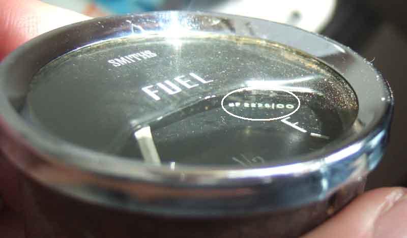 Updated December 2008 For fuel gauge and sender identification click on this thumbnail.
Temp section
Fixings
Information on internal and external gauge seals can be found here.
Electric Temperature Gauge: Added November 2008
The electric temperature gauge is similar to the fuel gauge, but using a sender on the cylinder head instead of the tank of course. Diagnosis and calibration is the same, substituting green/blue for the wire from the gauge to the sender. There is no earth/ground wire for the temp sender as it is screwed directly into the head. The sender can be very tight in the head so something other than an open-ended spanner which can slip off is desirable. If you don't have a 5/8" deep socket or box spanner then use a flare spanner as for the capillary gauge.
The early 180 degree gauges (both numeric and 'C-N-H') were capillary and dualled with the oil pressure, the later 'narrow angle' gauges were independent, electrically operated, and all 'C-N-H'. These gauges use a 'thermistor' (negative temperature coefficient resistor) sender in the cylinder head in which the resistance reduces as the temperature increases, so driving more current through the gauge to give a higher reading.
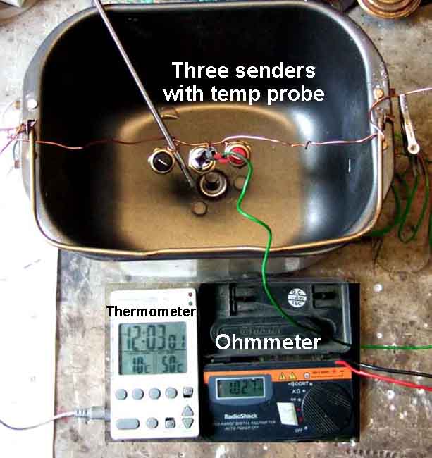 There are quite a few senders with different thread sizes and electrical characteristics, denoted by differently coloured insulators containing the spade connection. I have measured three senders that fit the heads (5/8" 18 thread) used on engines for the MGB and MGC as follows:
| �C | �F | Resistance | 'C-N-H' indication | ||
| Red | White | Black | |||
| 0 | 32 | 1605 | 1848 | 2283 | |
| 10 | 50 | 997 | 1055 | 1420 | |
| 20 | 68 | 640 | 650 | 928 | |
| 30 | 86 | 440 | 410 | 594 | 'C' (Cold) |
| 40 | 104 | 303 | 264 | 392 | |
| 50 | 113 | 208 | 174 | 263 | |
| 60 | 140 | 150 | 122 | 184 | |
| 70 | 158 | 108 | 82.5 | 129 | |
| 80 | 176 | 87.0 | 68.0 | 100 | |
| 85 | 185 | 70.0 | 54.0 | 82.0 | 'N' (Normal), about the temperature of a typical thermostat |
| 90 | 194 | 58.0 | 43.8 | 69.0 | |
| 100+ | 212+ | 47.0 | 35.1 | 58.3 | 'H' (Hot) |
Note that there were at least three gauges and three senders (part numbers, may be just two colours red and black) used. The red and white senders give fairly similar readings over most of the range (white starting off higher at low temps, but changing over at about 20C to be lower and hence give higher readings), but black gives lower gauge readings for a given temperature than the other two. For example at 82C (one of the standard stat temps) a red sender may put the gauge in the middle of the 'N', but the black sender would be just below N. Conversely a red sender would show Hot at 90 degrees, whereas for a black sender it would have to be 100 degrees, and that ten degree difference is pretty constant through the range. Also note that like the fuel gauge it is possible to adjust the gauge to some extent.
Also note that there are other colours, green possibly being for early Minis which did not have an instrument voltage stabiliser, and the temp sender like the fuel gauge sender operated in reverse and so would have a positive temperature coefficient i.e. increasing resistance with temperature.
From the Leyland Parts Catalogue and Clausager the senders and gauges changed as follows (only North American spec cars got the first three variants, all models had the final variant):
| Chassis numbers | Gauge | Sender | Notes |
| 138410-258000 | BHA 4686 | BMK 1644 GTR104 | Red insulator Start of MkII to 71 model year 18GF 101 to 18GK |
| 258001-368081 | BHA 5090 | BMK 1644 GTR104 | Red insulator Remainder of chrome bumper 18V584/585 to 18V 801/802 |
| 368082-410000 | BHA 5090 | 88G 580 | Red insulator? A couple of suppliers say it is black for all rubber bumpers, but the gauge didn't change between 1972 and 1976. However one source says the factory put a lower resistance sender in RB models to prevent owners panicking about the gauge reading! 75 and 76 model years 18v 836/837 to 18V 801/802 |
| 410001 on | AAU 3030 (BT 2231/01) | 13H 5602 or 13H 9715 or GTR101 | Black insulator 77 model year on 18V 847 (UK) and 883/884 (North America) on |
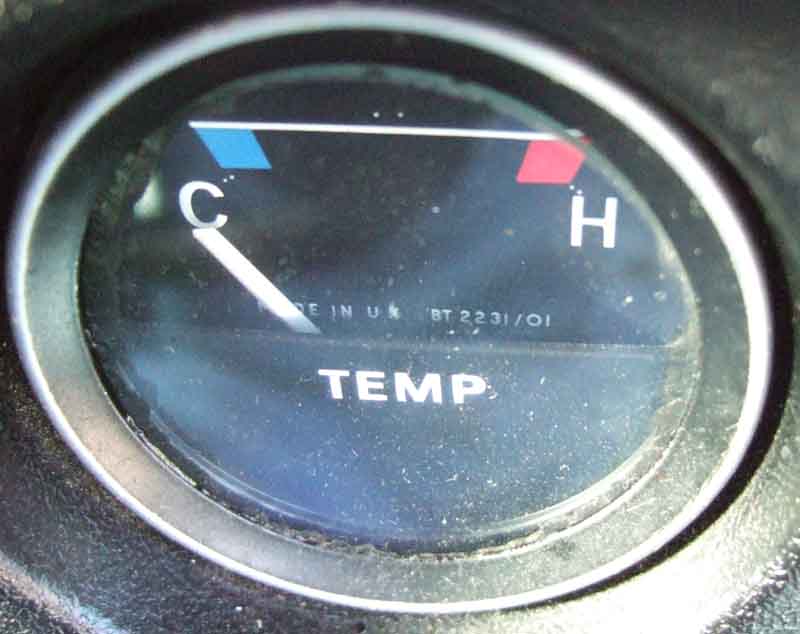 Note: The 'BT 2231/01' number for the last gauge is almost certainly the Smiths identification number and is given in the Leyland Parts Catalogue. Unfortunately there is no equivalent number given for the previous two gauges. This number can be found on the earlier 'needle down' gauges as shown in this example of a fuel gauge (on the rear part of the face, tucked up behind the front part of the face, circled) and more easily on the later 'needle up' gauges behind the lower part of the dial. Note the pairs of dots by the C, H and in the middle of the last gauge, these are on all the electric gauges and are used for factory calibration.
As you can see the only correlation between a sender change and a gauge change is for the 77 model year onwards, which is when UK and other non-North American spec cars got the electric gauge. One source gives the date of change as 71/72 i.e. when the gauge did change and the other (Roadster Factory) gives it as 74 i.e. the same as the Leyland Parts Catalogue when the gauge didn't change. Apart from the Leyland Parts Catalogue the online catalogues of Roadster factory, Moss and Victoria British only indicate two different types of sender - Roadster Factory changing at 74 as previously indicated, the other two changing for the 77 year. September 2015: Further research revealed multiple online parts sources showing pictures of BMK 1644 with the red insulator for 68 to 74 or 75, and 13H 6602 with the black insulator for 1975 on. This gives possible change dates of variously 71/72, 74, 75, and 77. However if there is the potential for a mis-match between gauge and sender, September 76 for the 77 model year (as indicated by the Parts Catalogue) is the most likely date for the change, as the fascias and the gauges changed on all cars at that point.
There has been another suggestion that perhaps the sender changed at the same time as the thermostat, to keep the needle centred on the gauge, but that doesn't tie in either as the thermostats changed shortly after September 64 then back again in March 69, which doesn't tie in with any of the gauge or sender changes from any source. Neither does it make logical sense when higher and lower stats were available for colder and hotter countries respectively, the gauge is only a general indication, and anywhere from just below the C to just below the H is part of the 'Normal' range depending on ambient temperature and usage.
Yet another possibility that has occurred to me is that the gauges have basically the same electrical/movement characteristics but the black sender was fitted as that has higher resistance across the range compared to the red, so would give lower gauge readings helping to avoid owner paranoia!
Electric Oil Gauge: Added November 2008
Fixings
The electric oil gauge is similar to the fuel gauge, but the connections shown in the Workshop Manual are a little confused. For the first year of Mk2 production for North America the schematics show it was wired the same as the fuel and temp gauges i.e. from the stabiliser, to the gauge, to the sender. After that full system voltage was applied to the gauge as it was the oil sender itself that contained the stabiliser. As there seems to only have been one sender for the electric oil gauge for both wiring arrangements I'm assuming that the wiring for 67 was in error. The gauge reverted to mechanical with a capillary pipe for the 1972 model year for the remainder of production.
October 2020:
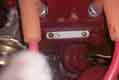 With the oil sender instead of a continuously varying resistance with changing oil pressure as is the case for changing fuel level and temperature for the other two gauges, the earth/ground signal from the oil sender switches on and off much like the voltage from the voltage stabiliser for the other two gauges. However the duty cycle i.e. the time it is on compared to the time it is off, varies with pressure as well as with system voltage. As it has no connection with the system voltage other than through the gauge it must sense this somehow and vary it accordingly, unfortunately I haven't had one to investigate internally, although my 1989 Toyota Celica had the same system (same physical appearance of the sender) so I was able to determine what the output from that looked like, at least. The sender is attached to a bracket mounting it to the now-unused rear mounting point for the dynamo.