
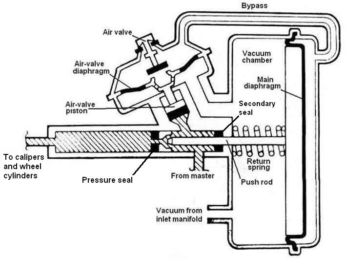
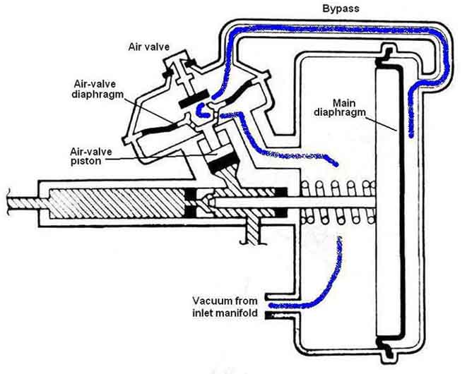
Engine running, brakes not applied. Vacuum from the inlet manifold is applied to the front of the main diaphragm, but also though the passage in the air-valve diaphragm, gap between the diaphragm and the air valve, the bypass pipe, to the back of the diaphragm. Thus the diaphragm has the same air pressure both sides and the return spring keeps it pressed to the back of the vacuum chamber:
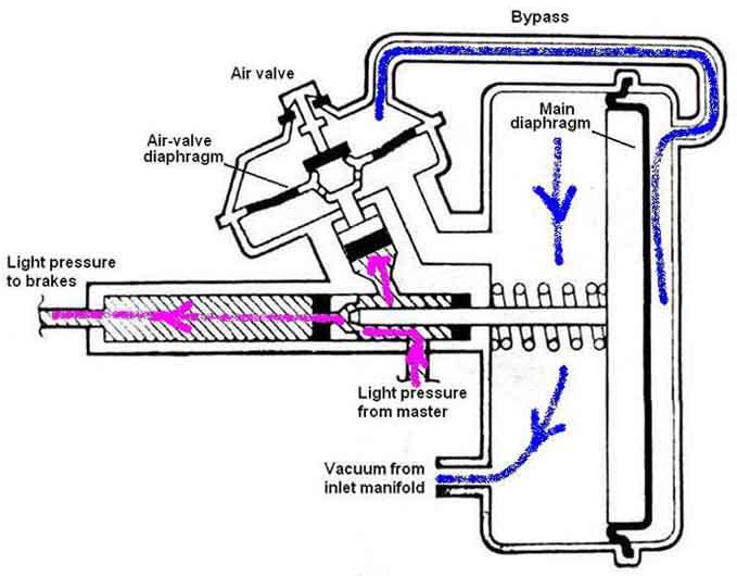
Brakes applied lightly. Light fluid pressure from the master is applied to the bottom of the air-valve diaphragm, and also through the space between the push-rod and the slave cylinder and onward to the brakes. Light pressure on the air-valve piston (called the reaction valve in AP/Lockheed documents) pushes the air-valve diaphragm up to the air valve, closing off the gap between the two, but not yet lifting the air-valve off its seat. Thus there is still the same air pressure both sides of the diaphragm and it remains pressed to the back of the vacuum chamber. This lack of assistance on light pedal pressure prevents the brakes coming on harder and more suddenly than one might wish:
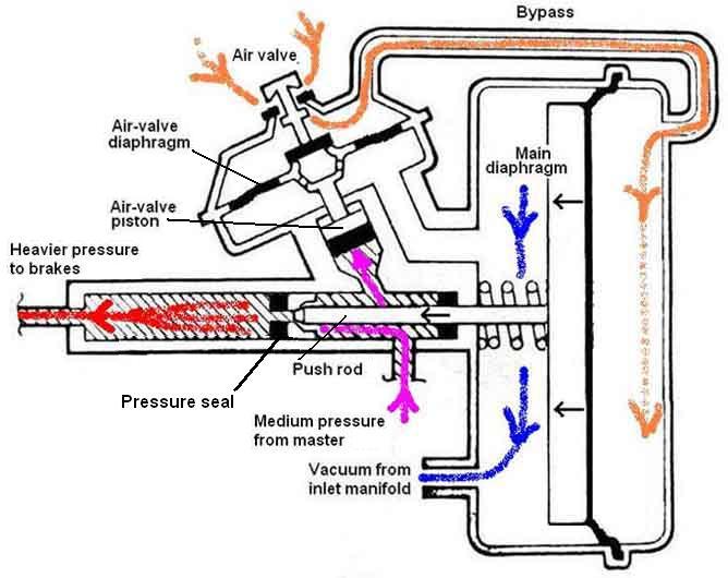
Heavier pressure on brake pedal. Heavier fluid pressure pushes the air-valve piston and its diaphragm further, which lifts the air-valve off its seat. This opens the air-valve allowing air at atmospheric pressure through the bypass pipe to the back of the diaphragm. With a depression on the other side the diaphragm is pulled forward, together with the push-rod, which closes off the gap between it and the slave piston, and pushes the slave piston along the bore to give a higher pressure at the outlet to the brakes than there is on the inlet from the master cylinder, which gives the 'boost' effect:
When the brake pedal is released, pressure on the air-valve piston is removed, it drops back, allowing its diaphragm and air valve to drop back also, and the latter closes the opening to the atmosphere. When the air-valve diaphragm moves away from the air valve the gap between them is opened up also, and manifold vacuum can now be applied via the bypass pipe to the back of the diaphragm again. This moves back to the rear of the chamber, pulling the push-rod back. The push-rod is connected to the slave piston with a loose connection (not shown in the diagram) so as well as opening up the gap between the two and releasing pressure from the brakes, it also pulls the slave piston back:
March 2024: Roger Thwaites had severe locking-on with a newly rebuilt servo that only released by using lots of power when trying to move the car. Studying the above Roger realised his bypass hose wasn't very secure and could well have prevented the vacuum being applied to the back of the diaphragm, added a couple of Jubilee clips and that solved the problem. Applying the large amount of power removed the vacuum from the front of the diaphragm as well, which allowed the spring to return the diaphragm and release the brakes
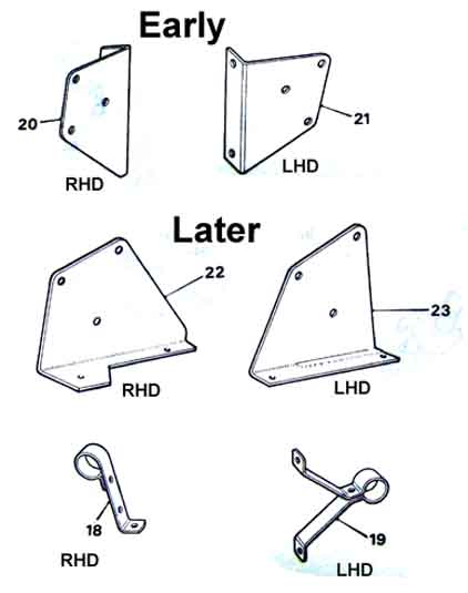
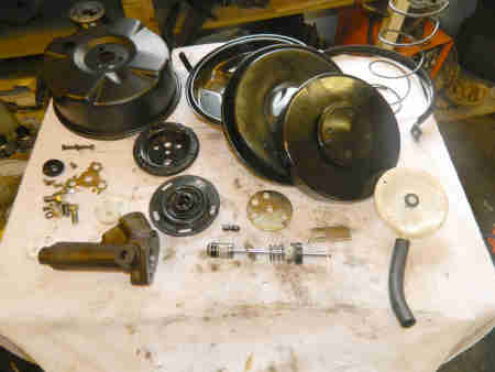
Things to note:
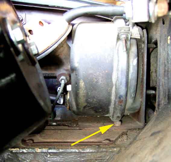
My 73 roadster - fixing bolt arrowed utilising the rear outer mounting point for the LHD pedal blanking plate, possibly another one further back, flattening part of the flange on the LHD pedal blanking plate:
Cylinder support - a crude 'S'-shape secured to the servo with a Jubilee clip:
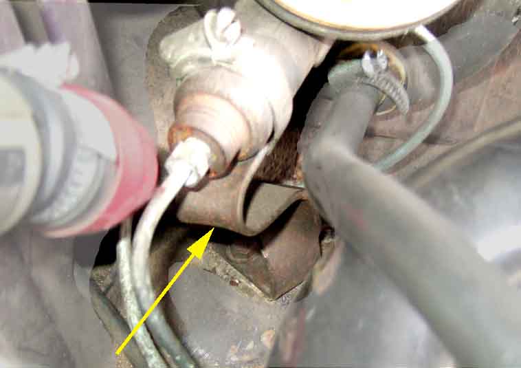
This has to be a PO retrofit as the servo didn't become standard on UK cars until more than a year after Bee was built and it's not listed under optional extras on the Heritage certificate.

V8 vacuum port on the inlet manifold:

4-cylinder vacuum port is on the rear end of the inlet manifold.
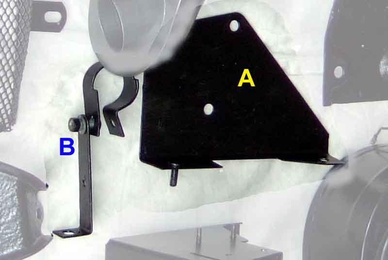
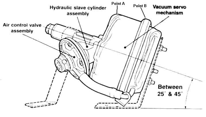
Image from AP/Lockheed fitting instructions (this link downloads a PDF) found on a Lotus Elan forum showing a pronounced upward angle of the cylinder, and the air-valve assembly pointing downwards, both of which will reduce the amount of air that can be trapped in the servo. But whether there is enough room to tilt the servo in an MGB by 45 degrees, or even 25 degrees, I don't know, as it is already pretty-well sandwiched between the bonnet and the shelf as it is. It could be tilted by about 10 degrees before point A rises above point B and so needs more vertical space, and once you start tilting it there is scope to move the whole servo down on the main bracket, so reducing the vertical space required:
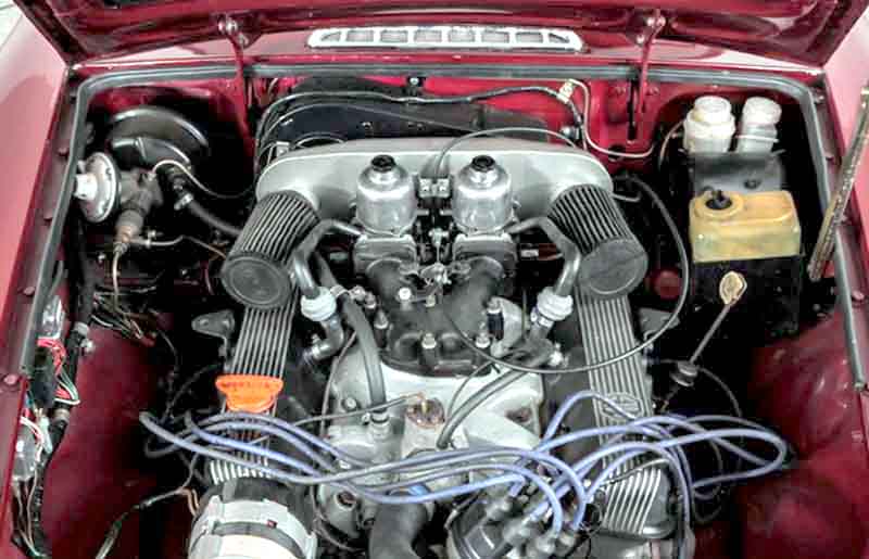
LHD single-circuit with servo: This picture of an LHD V8 clearly shows the servo pointing forwards as with one of the two (dual circuits) provided on North American spec MGCs. A number of LHD V8s were built for testing in North America, returned to the UK then sold into private hands in Europe. This appeared in an advert in Holland sent to me by Hans, one of the test cars was Damask Red which this appears to be. However North America required dual circuit brakes from 1967 and I can't see a second one, so maybe not:
 See this from The Landcrab Forum.