
The 16AC externally regulated model:
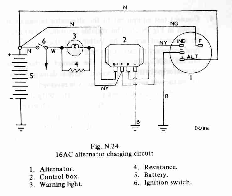
Note that item 2 labelled 'control box' is an electronic voltage regulator and not an electro-mechanical control box as used with the dynamo. Note also that it has a 'B+' terminal connected to the battery along with the alternator output terminal (+) which makes it a 'battery-sensing' regulator (there were 'machine-sensing' versions of the 4TR without this B+ terminal).
'Battery-sensing' uses the voltage at the battery cable on the starter solenoid via a 'sense' wire to control the alternator output voltage, 'machine-sensing' uses the voltage at the alternator output terminal itself. Under high current loads some voltage is 'lost' in the resistance of the output wire from the alternator to the battery terminal and with machine-sensing alternators this results in a reduced system and battery charging voltage. But with battery-sensing this lost voltage is compensated for by the voltage regulator causing the alternator to output a higher voltage to maintain the system and the battery charging voltage at the correct level.
The first 16ACR alternators in 1969 had two connector plugs with four wires) one of them linking the two plugs) and were also battery-sensing but in 1972 they changed to machine-sensing with single plugs with only two wires - a thick output wire and a standard-gauge INDicator wire - with a modified voltage regulator and surge protection. But only for one year because for the 1973 model year they changed to battery sensing again having a third terminal (BATT+) with a standard gauge wire going to the battery cable terminal on the solenoid in addition to the output wire on the + terminal. Other information indicates the alternator itself changed in 1976 but there are 1978 versions of the 18ACR still with battery-sensing connectors. In 1978/79 the schematics show a change back to machine-sensing albeit still with three wires but two of them were now thick output wires which increases current carrying capacity so reducing lost voltage that way instead of using a 'sense' wire to increase alternator output.
The internally regulated '2-wire' machine-sensing alternator:

The internally regulated '3-wire' battery-sensing alternator with the additional wire from a BATT+ terminal to the starter solenoid:

What's inside: There is a field winding on the armature to generate a magnetic field, three fixed stator windings to provide the output voltage and current, a diode pack consisting of nine diodes, and a voltage regulator. For connection to the outside world it has the positive 12v output terminal, an IND terminal, an earth through it's physical mounting to the engine, and in battery-sensing applications an additional BATT+ terminal.
Voltage Generation: Unlike a dynamo which has its field windings fixed to the dynamo casing and output windings on the armature, the alternator is the other way round. The armature brushes on a dynamo limit the maximum current that can flow both because of the resistive nature of the graphite or carbon brushes, and because they are running on a commutator which is continually connecting and disconnecting current which creates arcing, and high current damages the brushes and the commutator over time. By reversing the functions even though graphite or carbon brushes are still used in an alternator they are running on continuous slip-rings rather than a commutator so arcing is eliminated, and field current is much less than output current. Another benefit is that because the field-wound armature of the alternator has a significantly lower mass or weight than the output-wound armature of a dynamo it has a higher maximum rpm. This is utilised by the alternator having a smaller diameter pulley than the dynamo so it spins faster for a given engine speed, which also increases output, and an alternator will charge down to about 600rpm. The downside of all this is that alternating current (AC) is generated in the stator of an alternator (hence its name) rather than the direct current (DC) from the commutator of a dynamo. AC is no good for charging a battery and operating many automotive electrical systems, so it has to be 'rectified' to DC which is the job of the diode pack. But first, the stator or output windings.
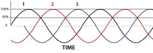
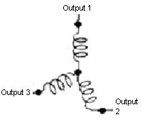 Whilst the field winding is a simple coil of wire wound onto the armature the stator is attached to the body of the alternator and consists of three coils connected in 'star' formation i.e. one end of the three coils are connected together and the other ends provide three AC outputs. Because of the way the three coils are positioned and interconnected they generate AC in three different phases, i.e. three overlapping positive pulses of current and three negative for each magnetic pulse from the field winding on the armature. Additionally the armature has 12 poles - each of which generates an output pulse in the stator windings - so generating 36 output cycles of AC for each revolution of the armature:
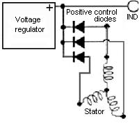
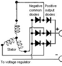 As said AC is no good for automotive electrics and this is where the diode pack comes in. There are three positive output diodes, three positive control diodes, and three negative diodes. The negative diodes are used for both output and control. Separate positive diodes are needed as they go to different parts of the alternator. The diodes are connected such that negative half-cycles from the stator are converted to positive half-cycles - full-wave rectification, so now we get 72 pulses of positive voltage for each rotation of the armature, which gives a much steadier DC current flow. The positive output diodes are all connected to the positive output terminal of the alternator and the negative diodes are all connected to earth:
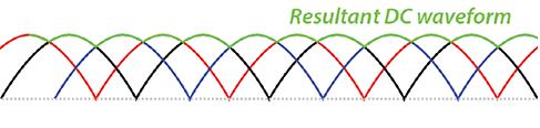
There is still quite a lot of 'ripple' in the output voltage, but when connected to a 12v car battery this ripple is smoothed to become to all intents and purposes a steady voltage, and it is this steady voltage that powers all the cars components. This is why an engine with an alternator should never be run without a battery connected as this further smoothing action is lost and some quite high voltage spikes can be generated which are capable of damaging electronic components at least, and may even blow bulbs.
Voltage Regulation:
 The three positive control diodes feed positive voltage to one side of the field winding, the other side of the field being connected to the voltage regulator. The voltage regulator 'sees' the voltage on the alternator output terminal (machine-sensing) or via the 'sense' wire on the BATT+ terminal (battery-sensing) the voltage on the battery cable on the starter solenoid. Changes in electrical loads from the car changes the current being drawn from the alternator, which because the alternator stator windings have resistance causes a certain amount of voltage to be 'lost' inside the alternator. As the current increases - more loads switched on - the lost voltage increases, which means the output voltage reduces, and vice-versa. Left to its own devices there would be huge variations in output voltage with changing electrical load which is undesirable, ideally we want to maintain a constant voltage at all times.
 The voltage regulator is effectively a variable resistance (or control valve) between the field winding and earth. As more electrical loads on the car are switched on and output voltage is seen to drop, the voltage regulator senses that and reduces the resistance in series with the field winding allowing more current to flow. This increases the magnetic field around the stator and hence increases the output voltage to compensate for the internal losses. Conversely as electrical loads are switched off and current through the alternator reduces the output voltage rises. This causes the voltage regulator to increase the resistance in series with the field winding - so reducing the current - which reduces the magnetic field and hence the output voltage. This increasing and reducing of current through the field maintains the output voltage at a nominal 14.5v which supplies all the cars electrical loads as well as trickle-charging the battery.
In theory these changes are instantaneous and give a constant output voltage under all conditions. However alternators cannot output their maximum current at low engine rpms and each alternator has a maximum current that it can deliver without damage. As the maximum current capacity of the alternator is approached each further increase in current is not completely compensated for by the voltage regulator which means the output voltage reduces. Each further increase in current causes the output voltage to fall towards nominal battery voltage i.e. about 12.8v and can be seen on a voltmeter. Any increase in current beyond that will be taken from the battery, reducing its voltage and gradually discharging it. The MGB Workshop Manual gives the maximum current (35 to 45 amps depending on model) at 6000 rpm, it will be less than that at idle and lower engine speeds when even moderate currents will cause the system voltage to be lower than 14.5v. With 80 amp, 90 amp and even higher alternators fitted to modern cars the voltage drop at idle and with increasing load is much less noticeable on a voltmeter. If a significant part of your journey is stuck in traffic for any length of time at night and in cold and wet weather, consideration might need to be given to reducing the load by not sitting there with the brake lights on (3.5A) and switching certain things off such as headlights (7.5A), heated rear screen (8A), wipers (3A) and heater fan (3A). The more your journey involves driving at 30mph plus the less this is an issue.
Ignition Warning Light:
 The INDicator terminal is connected through the ignition warning light to the ignition voltage supply controlled by the ignition switch. It has the same functions as originally with dynamo systems - i.e. lighting up to show the ignition is switched on, and then extinguishing as the engine is started and the dynamo or alternator starts charging. With the alternator not charging and the voltage regulator only 'seeing' battery voltage i.e. 12v on the + (or BATT+) terminal it is set to its lowest resistance (valve fully open) so current from the ignition switch passes through the ignition warning light, field winding and voltage regulator to earth so the warning light glows brightly. When the alternator is running and charging there is 14.5v from the stator via the control diodes to the IND terminal, and from there to one side of the warning light. System voltage is now 14.5v connected via the ignition switch to the other side of the warning light, so with 14.5v both sides the light is extinguished.
However that is of secondary importance in alternator systems. Dynamo systems have residual magnetism in the iron components which generates a small output voltage as soon as the armature starts spinning, which is fed to the field windings by the control box, which generates a larger output voltage and so on up to full output (see Dynamo Control Box for details). Alternators have much less residual magnetism and need something else to feed that initial current through the field windings to start generating an output, and that is where the warning light comes in. By passing current through the field winding - ignition warning light glowing brightly - it 'primes' the alternator to start charging once the engine is started. However this isn't enough by itself, which is why if you start an MGB without choke or throttle the warning light probably won't go out, the engine has to be revved above about 900rpm. At that point the process is the same as for the dynamo i.e. generated output is fed to the field which generates a higher output and so on, until the output reaches 14.5v. However in practice even without a working ignition warning light the alternator on an MGB (used at least, maybe not brand-new) should start charging if the engine is revved to about 3k, and once charging it should then continue to charge down to the normal level of about 600rpm. Dynamo systems being less effective will stop charging at about idle speed, which is when you see the warning light flickering. But just as alternators have a higher output at a given engine speed they also keep charging to a lower engine speed because they are spinning faster at idle. As all alternator-equipped cars should have an idle speed of 700rpm or more they should always (once revved to 900rpm after starting) be charging at idle, and you should never see the warning light glowing once it has gone out ... except when you switch off a running engine.
It's important to be aware that while a number of causes of charge failure will result in the warning light glowing while the engine is running (if you spot it!) there are some that will not. Primarily in the latter is when the alternator plug has fallen out or not been replaced after work! (BT, DT ...). However in that case the warning light will not glow when first turning on the ignition so checking for that every time is good practice. The workshop manual lists six instances of failure that have varying effects on the warning light, temperature and noise but with the latter two unless you know what is 'normal' you may not recognise when a fault has occurred.
When you switch off a running engine with the alternator charging, the ignition switch disconnects system voltage i.e. nominally 14.5v from the ignition switch side of the warning light. However that side is also connected to all the ignition powered circuits, each of which is connected to earth at some point. Back at the alternator, while the engine is spinning down the alternator is still generating it's output voltage, which is connected to the IND terminal via the control positive diodes and hence to the alternator side of the warning light. So the warning light has alternator voltage one side, and on the other via the coil, fuel pump, instruments and so on it has several relatively low resistance paths to earth, so the warning light will glow again. But only while the engine is spinning down, as it slows the light will flicker and die. This glowing at switch-off caused a problem when the ignition relay was first provided.
When that happened it powered all the ignition circuits except for the ignition warning light which still came off the ignition switch. As above when a running engine is turned off voltage from the IND terminal via the ignition warning light onto the relay winding replaces the voltage that had been coming from the ignition switch. This is enough to keep the ignition relay operated, which supplies power to all the ignition circuits including the coil and keeps the engine running normally even with the key out and in your hand! On MGBs other than for North America the problem was immediately apparent and the warning light connection was moved to the output of the ignition relay along with everything else. This means that the ignition switch releases the relay and the engine stops normally.
But for North American spec cars (which had a different harness to other markets) this problem wasn't immediately apparent because they already had an anti-runon system which stops the engine at switch-off by starving it of fuel. This was fine until a fault developed in the anti-runon system which again allowed the engine to continue to run with the key out and in your hand - more details on this here. Because of that 1978 models had the coil feed wire moved from the output of the relay to its input side together with the wire from the ignition switch. The ignition switch now cuts power to the ignition coil directly i.e. independently of the relay and is an alternative way of curing the problem. The engine now switches off as normal, and although initially voltage and current still flows backwards from the IND terminal through the ignition warning light to the ignition relay winding, the relative resistances of ignition warning light bulb, coil plus ballast and relay winding means that the voltage is no longer enough to keep the relay operated, so cutting power to the remainder of the ignition circuits.
Note that replacing the ignition warning light with a 12v LED is pointless and probably counter-productive (although would get round the 'continuous running' problem caused by a faulty anti-runon system on 1977 North American models). The current through an LED is much less than a filament lamp and will reduce the priming current through the field which may impact on when the alternator starts to charge and the engine may need to be revved higher on starting. Also the voltage/brightness characteristics of an LED can be very different to an incandescent lamp so you may find it glowing or flickering when it shouldn't. As well as its priming function (which could be done with an internal resistor instead) and showing when the ignition is on (Americans call this feature the idiot light as 'only an idiot needs to be told they have just turned the ignition on') the warning light has a diagnostic function by glowering or flickering when certain faults have developed inside the alternator, and when there are certain bad connections in the car's wiring and components. Anything that causes a difference in voltage between the IND terminal on the alternator to one side of the warning light and the ignition supply to the other side of the warning light will tend to make the light glow - the higher the difference the brighter the glow.