

The 4-fuse fusebox showing the orientation and wire colours from the rear. Make sure the link between terminals 1 and 3 goes at the top front. The 'correct' position for the red/green is shown, but electrically it doesn't matter which of the top two front spades it goes on. Strictly speaking the red wires for the left-hand side of the car go on the top fuse, but electrically it doesn't matter if the left and right sides are reversed. Some white wires changed to white/brown with the introduction of the ignition relay for the 77 model year.

Showing the orientation and wire colours from the front. Terminal numbers are visible when fitted, 1 and 2 (circled) should be at the top.

1972 model showing two brown wires each in separate spade connectors and three greens with two of them sharing a spade connector as there are only two spades each end of each fuse. Note the four reds for the position markers (aka parking lights) two on each fuse which also share spade connectors even though there are two unused spades. One wire goes to each corner and sharing spade connectors like this ensures one fuse feeds one side of the car and the other fuse the other. The only reason I can think of for that is if one of the fuses has blown and you don't have either of the spares in the fusebox then the remaining fuse could be used to power the driver's side which would be safer than having just the kerb-side powered. Presumably the black sleeving on the two lower reds is used during manufacture to ensure the correct reds share connectors: (Nat)

Typical fuse-holder corrosion.

Fusebox cover with spare fuses.


Mk2 North American, all V8s, and rubber bumper cars gained hazard flashers and the fuse for that in RHD cars at least was initially behind the centre console:

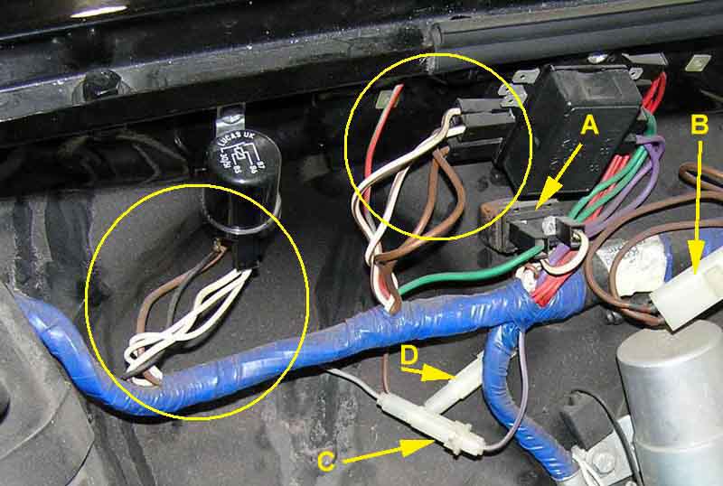
Later hazard fuses ('D' here), and first one (all markets) then two (RHD) additional green circuit fuses when the accessories fuse was deleted. The North American anti-runon valve fuse ('C') also appeared under the fusebox with an automatically resetting thermal circuit breaker ('A') for the cooling fan. 'B' is the North American connector in the brown circuit where two wires came up from the starter solenoid then split into two separate feeds which reduces the volt-drop under heavy load conditions.

Slip of paper showing '17A continuous' and '35 AMP blow', both unambiguous.

'35A' on an end-cap ...

... and the only number on a slip of paper less so.
