Overdrive Electrics
Fault diagnosis - D-Type
Fault diagnosis - LH-Type
LH Solenoid covers/labels
LH Hydraulics
Overdrive 'Pulsing'
Overdrive_Fusing
Overdrive_Replacement
Overdrive Sequencer Relay
How many were there?
Although specific to the D-type OD the very clear description of how the Laycock overdrive changes ratios in this document is also applicable to the LH-type:
 The gear train consists of a sun-wheel (A), planet wheels (B), planet wheel carrier (D), and annulus with ring gear (C) inside which drives the output shaft. The input is via the planet carrier and when the sun gear is locked to the ring gear the whole unit rotates as a single unit to give direct drive. But when the sun-wheel is held stationary the planet carrier rotation turns the planet wheels and hence the ring gear which is 'overdriven' at a higher speed than the planet carrier to give the overdrive ratio. Believe it or not this is exactly the principle used by the Sturmey Archer 3-speed hub dating from 1902 that many of us will have been familiar with when we were in short trousers. How does that give three gears? The Laycock unit always applies the input to one of them (the planet carrier), and either locks the sun-wheel to the annulus or to the casing to give either direct drive or the overdrive ratio. The Sturmey Archer does basically the same, but can reverse the input and output so that the ratio difference can either be used to gear the output down i.e. for first gear, or to gear it up for 3rd gear, with direct drive for second gear. Lots of videos and descriptions online, with varying degrees of complexity and confusion!
Understanding what determines the OD ratio is complex, and comparing the drawing above with endless descriptions of epicyclic gearing is no help. The ratio for the simple system above is determined by the number of teeth in the ring gear, divided by the number in the ring gear plus the number in the sun gear. The number of teeth in the planet gears has no effect. But the Laycock planet gears have two diameters - the larger engaged with the sun-wheel and the smaller with the ring gear and now the planet gear tooth count does have an effect ... and makes the calculation a lot more complex!
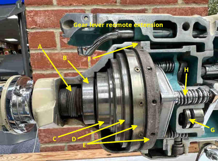
In this cutaway (I think of a D-type) 'A' is the speedo drive worm gear; 'B' is one of two output shaft bearings on the annulus output shaft (the other is close to the drive flange); 'C' and 'D' are the annulus that drives the output shaft - 'C' contains the one-way (aka sprag' or 'trapped roller') clutch and 'D' contains the sun-wheel, planet gears and ring gear; 'E' is the sliding member with internal clutch to the outside of the annulus (OD disengaged) and external clutch to the brake ring in the casing (OD engaged); 'F' is the brake ring in the casing; 'G' is one of two pistons and bridges that pulls the sliding member clutch away from the annulus and towards the brake ring; 'H' is one of four sliding member return springs: (image from MGOC November 2024 Newsletter blog on the Laycock overdrive by Roger Parker - copyright information requested)
This end of the OD (LH-type in this case) bolts to the gearbox. 'I' is the oil pump; 'G' are the pistons and bridges, with rods passing through holes in the casting that pull the sliding member towards the viewer to engage OD; return springs 'H' behind the casting; 'J' is the sun-wheel bearing and carrier; 'K' is the sliding member with the planet wheel carrier seen through the holes; 'L' is the two sets of splines driven by the gearbox shaft for the planet wheel carrier (outer set) and one-way clutch (inner set) :
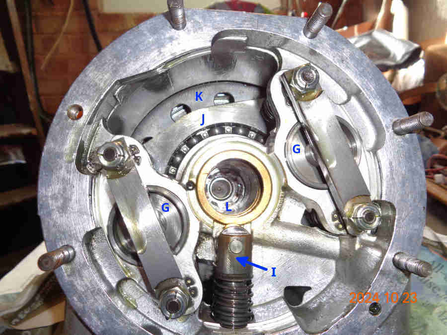
In use the eccentric cam on the shaft drives the oil pump. In direct drive the return springs 'G' are pushing the sliding member and its inner clutch 'E' away from the viewer against the outside of the annulus 'D' and the two are locked together. However forward drive is through the one-way clutch which has a set of rollers in wedge-shaped spaces that move to lock the sun-wheel to the annulus. With OD engaged hydraulic pressure pushes the pistons and bridges 'G' towards the viewer which pulls the sliding member and its clutches 'E' out of engagement with the annulus 'D' and into contact with the fixed brake ring 'F'. This stops the sliding member rotating and allows the epicyclic assembly to step up the gearing of the annulus and output shaft relative to the gearbox shaft. The annulus is now rotating faster than the sun-wheel which moves the rollers in the one-way clutch the other way and unlocks it. As OD is disengaged hydraulic pressure is released and the return springs 'H' push the pistons and bridges away from the viewer (to the left in the cut-away above) to push the sliding member out of engagement with the brake ring and into engagement with the annulus. All parts of the epicyclic gearing now rotate as one to give direct drive - again through the locked one-way clutch. While the sliding member is moving between the annulus and the brake ring the one-way drive is providing direct drive preventing any sensation of 'clutch slip' between its two positions. But the main function of the one-way clutch is in direct drive in a forward low gear to prevent any slippage of the sliding member clutch on the annulus under high torque conditions. In reverse the one-way clutch can't lock as it is rotating in the opposite direction, nor on the overrun (OD engaged or not) as the relative forces have reversed with the annulus race now driving the sun-wheel race. But in both cases 'helix forces' (WSM description) apply additional load to the sliding member clutches to prevent slippage.
The one-way clutch is worth looking at in more detail: (Renold video):

The one-way clutch is similar to a roller bearing except that rather than being held in a cage each roller is contained in a wedge-shaped space, and the two races can only move relative to one another in one direction, not both. The inner race is driven by the gearbox shaft with the outer race connected to the annulus and the output shaft. In the left image when the engine is driving the car forwards with OD disengaged the inner race wants to turn clockwise relative to the outer race, but the rollers are forced into the narrow part of the wedge. This locks the two races together and provides drive with no chance of the OD clutch slipping under high torque in a low gear. With OD engaged on the right the sliding member is locked to the brake ring in the casing and the epicyclic gearing is turning the output shaft to the wheels faster than the input shaft from the gearbox. Hence the outer race is turning faster than the inner race, the rollers move into the wider part of the wedge and the one-way clutch is unlocked.
Updated December2016: There were three types of LH OD for the MGB - chrome-bumper 4-cylinders cars; 4-cylinder rubber-bumper cars and V8 each with different (in theory) colours for the solenoid cover/label. The 4-cylinder chrome bumper and rubber bumper have different speedo drive gears, the V8 both CB and RB has the same speedo drive ratio as the chrome bumper 4-cylinder but operates at a higher pressure. The MGC also had the LH OD, details unknown. Speedos have the turns per mile (tpm) stencilled on the dial - 4-cylinder chrome-bumper cars have a 1280 tpm speedo and all V8s have a 960tpm speedo, whereas 4-cylinder rubber-bumper cars have a 1000 tpm speedo. On the face of it the V8 should have different speedo gearing to the chrome-bumper 4-cylinder, but they have different axle ratios as well which also has to be taken into account. The 4-cylinder ratio is 11/43 and the V8 14/43 i.e. 27% lower prop-shaft rotation of the V8 for the same road speed. But the V8 speedo would over-read by 25% with the same turns of the drive cable, so they almost cancel each other out, bar 2%. Another factor is the wider 175 tyre of the V8 but the same profile, which results in a 2.5% reduction in wheel and hence prop-shaft rotation for the same road speed. This seems to be resulting in an overall 2.5% reduction in V8 speedo reading for a given road speed, whereas perhaps one would expect it all to work out at 0.5% over-reading, but I must confess I can't be certain either way!
The D type is not as strong as the LH and has a vacuum switch and relay to prevent the driver from disengaging OD under certain conditions - high revs and no throttle - which could overstress the unit. The LH type does seems to be strong enough as the factory felt that 'driver education' was sufficient, although on the V8 breakages were found early on so OD was limited to 4th gear including retrospective mods. Note that the restriction of OD the 4th gear only on later North American models was solely due to complications with the gearbox switches and TCSA. The wiring and a description of the vacuum switch and relay circuit can be found here ![]() . The Service Instruction Manual for the D-type as fitted to Standard-Triumph vehicles can be found here.
. The Service Instruction Manual for the D-type as fitted to Standard-Triumph vehicles can be found here.
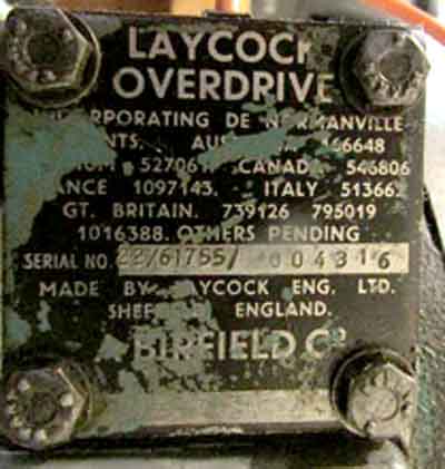
Lots of different types around although most don't apply to the MGB. Of the numbers stamped onto the cover Vance Navrette writes:
The TR J-Types delivered a 25% OD factor (e.g. for every revolution on the input shaft, the output shaft rotates 1.25 revolutions).
TR A-Type ODs delivered a 22% overdrive.
TR J-Type ODs delivered a 25% overdrive.
Volvo J-Types delivered a 27% or 28% overdrive."
"1955-1964 = A-type, non-synchronized first gear - 22/61374/ - TR2 from TS5979-TR4 Oct. 64
"1964-1967 = A-type, synchronized first gear - 22/61712/ - TR4/4A Oct. 64-67 solid rear axles.
"1965-March 1971 = A-type, synchronized first gear - 22/61753/ - TR4A (IRS only), TR250, TR6
"April 1971-November 1972 = A-type, synchronized first gear - 22/61985/ - TR6
"December 1972-1974 = J-type, synchronized first gear - 25/115838/ - TR6
"1975-1976 = J-type, synchronized first gear - 25/115876/ - TR6
"22 and 28 are also common to Austin Healeys though (all Healeys used A-types).
"Spitfires from 1974-1981 also used the 25 spec J-Type."
In common with many of the above MGBs used the 22% type, with a black label on CB cars and a blue on RB. There are said to be different colours for MGC and V8 to denote higher pressures perhaps, but opinions vary as to which was green (MGC?) and which was red (V8?). Overdrive Repair Services in Sheffield who are ex-Laycock engineers have told me that if they ran out of a colour they used whatever they had to hand, albeit with the correct numbers stamped!
The second group of numbers are initially five digits starting with '6', the remaining four digits going up in jumps. Then from the above apparently changing to six digits starting with '11', with the remaining four digits continuing to go up in jumps. This group could indicate small internal changes of design or component, but I'm guessing, they don't seem to relate to date unless it is a code. The final group of digits is the individual serial number of the unit.
The following are from 4-cylinder MGBs. The first pair carry the same numbers but represent two different eras of production changing in the mid-70s, see below. Of the second pair the black label should have a 1280tpm speedo drive gear and the blue label should have a 1000tpm speedo drive gear, but they both have the same reference number:
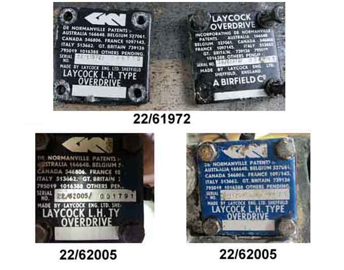
Change in ownership - Laycock was sold to Birfield in 1938, and although GKN bought Birfield and hence Laycock in 1966 the units were badged Laycock/Birfield until the 'mid 1970s' (Wikipedia) when it became 'GKN'. However the '61972' of the top pair implies it could have been the very early 70s going by the dates above:
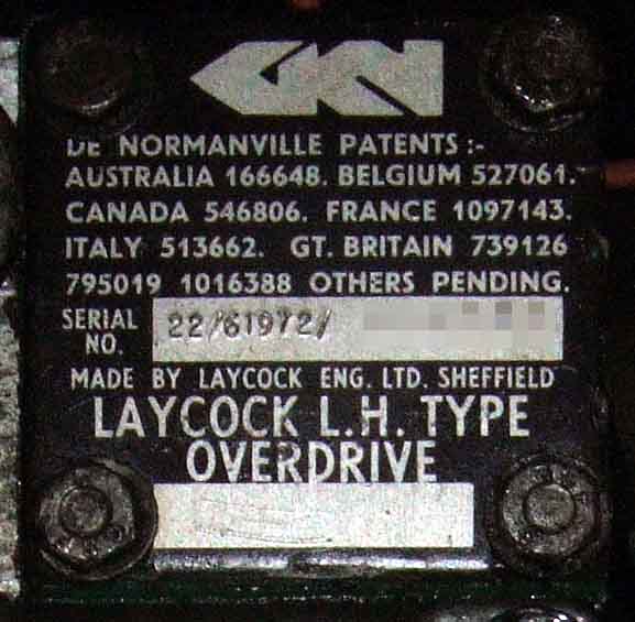
Bee's plate - '61972' seems quite common for 4-cylinder cars and is in line with the A-type sequence above. 'GKN' indicating that the badging changed by September 72 (Bee's build date) as well as the dates above:
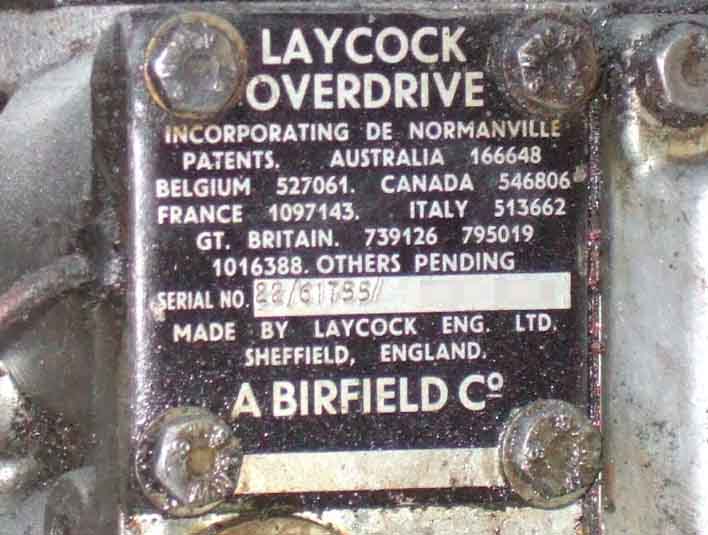
V8s always used a 960tpm speedo drive i.e. for both CB and RB, this is Vee's plate. A number lower than one might expect for a 1975-built car and earlier than Bee's, although V8s probably had their own number series to represent the different operating pressure. Also the earlier 'Laycock/Birfield' plate, so maybe Vee has had a replacement OD ... which may have come from a 4-cylinder!:
The plate from a V8 owned by Geoff Dunlop in Australia that started it all - one of the higher five-digit numbers as on the J-types above. However some sources indicate this should be red with green being for MGC:
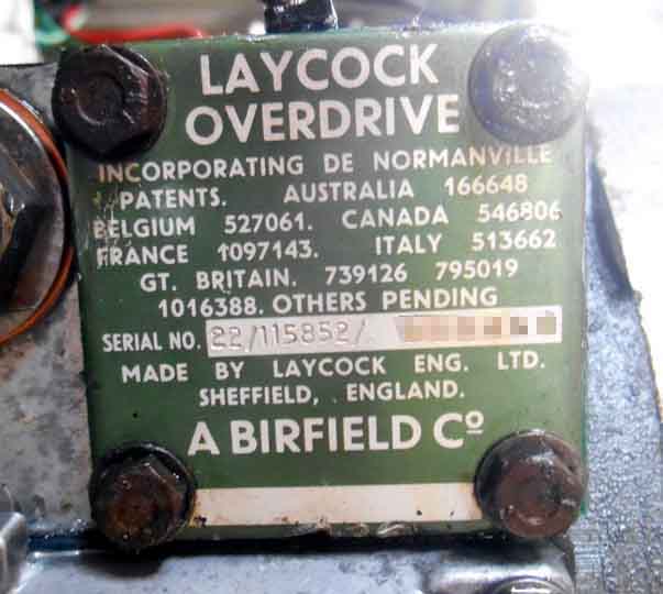
Reputedly an MGC plate with the same reference number as Vee's above although information is that they had a green label. MGCs seem to have had a 1020tpm or a 1120tpm speedo depending on which axle was fitted, which varied according to year and whether it had standard, OD or automatic transmission. MGCs also had 15" wheels with 185/70 tyres which result in a speedo under-read of 6% compared to the standard MGB roadster. So just like a black-label OD can drive a 960tpm V8 speedo, I suspect the same OD can be used for an MGC with a 3.7:1 axle and an 1120tpm speedo, or a 3.307:1 axle and a 1020tpm speedo. The second group of numbers does fit in with the dates given above for MGC production:
Solenoid Cover Gasket March 2017 There is oil in the solenoid valve and although they have a gasket they, where the wire exits, and possibly the screw threads, can leak. Bee had started dropping clean oil recently, from the sump area, although given the size and shape of the gearbox and OD it could have been coming from anywhere and running to the lowest point. Note that although the solenoid cover (NOT the sump!) is at the lowest point it can be removed without draining the oil.
Originally I suspected the drive flange oil-seal, so tied a strip of white cloth round it between the flange and the seal, but it didn't stop the drip and the cloth was still clean. Next step was to tie a set of longer strips round the gearbox - in front of where the gear lever remote housing attaches, where the OD attaches to the gearbox, and where the rear half of the OD attaches to the front half. The drips still appeared from the sump area but to one side i.e. under the solenoid cover, so that was a likely candidate. It could also be the relief valve plug, and the sump gasket, but as certainly the latter and possibly the former would require draining the gearbox whereas the solenoid cover doesn't, I decided to tackle the solenoid cover first.
The screws (8mm socket needed) were barely tight, but rather than simply tightening them I removed the cover, cleaned the faces (although the gasket came off almost completely intact), and fitted a new gasket (37H1941) with a smear of non-setting flange sealant both sides and on the screw threads. Tightened the screws gradually and diagonally, using just a nut-driver and not the 3/8" socket handle. Oil does drip out steadily with the cover off, but no flood, not even when the solenoid and its plunger are removed. I left these alone as they weren't causing any problems, but if leaving the car with the cover removed it would be advisable to put a clean container underneath to catch any bits that may fall out under their own weight.
However that didn't fix the leak, and in fact the OD stopped working altogether when warm shortly afterwards. Electrical tests showed the problem was electrical, and turned out to be the earthing strips on the end of the solenoid coil having lost tension. I retensioned those, changed the O-rings as well, which fixed both problems.
- The LH solenoid has three O-rings, and if the medium-sized one of these should fail it may not develop sufficient pressure to engage OD, as it allows oil to escape as if the solenoid had failed to operate. Likewise if the plunger jams, or the ball (BLS106, 3/16") is not seating properly. The solenoid is accessible from underneath by removing the square information plate beside the sump, draining the oil is not required. Incidentally the small O-ring inside the solenoid assembly, and the large one on the top-plate, contribute to preventing oil leaks, as well as the gasket above the information plate, and the rubber seal around the solenoid wire.
- There could be problems with the relief valve, accessed by removing the hex plug by the sump, which can be done without draining the oil. This also contains a ball-bearing, but the usual suspects only show this as part of a kit and it is not separately identified in the Leyland Parts Catalogue.
- There is a non-return valve ball and seat in the pump which could be leaking back, or the plunger may have jammed if has not been aligned correctly or the return spring is weak. This ball and seat are only available from the usual suspects as a pair, and the ball is not separately identified in the Leyland Parts Catalogue. This is accessed by removing the sump, which requires draining the oil, and needs a special tool to remove the pump plug (or a pair of stout long-nose pliers with the ends in the holes, turned by grips). I've not had any need to dig-in to the pump but Nathan Peach came up with a really good check when he was investigating his after changing several parts but still not working. He found no oil in the new solenoid so suspected the pump, and after draining the oil and removing the sump he turned the prop-shaft while looking up inside the OD with a torch he could see the pump but it wasn't moving. He went to remove the pump but as soon as he turned the securing plug something clicked into place, and after that he could see the pump operating. The end of the pump that carries the roller has a flat side and a rounded side - the flat side goes towards the rear of the OD, and it's this flat lying against the casing that orientates the pump correctly. Nathan also writes that the pump plug is a lot easier to fit if you use the prop-shaft to turn the lobe of the cam away from the pump!
Overdrive Pulsing Updated April 2017
| "One vexing symptom of an Overdrive problem that is not mentioned in the factory manual is a 'pumping' effect during engagement when the car is driven in direct drive, even though when driven in Overdrive all appears normal. This is caused by a problem that is very simple to fix. When the system is operating correctly, a buildup of hydraulic pressure from the pump is directed to the two operating pistons and moves the sliding annular clutch (conical clutch) unit. Its outer brake surface then comes into contact with the stationary brake ring, and then the complete sliding member and the sun gear will consequently cease to rotate. With the solenoid deactivated (i.e., Overdrive switches off), the solenoid plunger does not retract fully, and the springiness in the small O-ring at its tip is enough to push the piston and ball back into its seat once the pressure has bled off. This in turn causes the pressure in the actuating system to increase, which in turn causes the Overdrive to engage again. Past a certain level, there is enough pressure to force the plunger back a bit until the pressure bleeds off and the cycle is repeated again (at a frequency of about every 2 seconds). Normally, as the sliding annular clutch (conical clutch) unit of the Overdrive unit starts to move during the engagement process, the Overdrive unit temporarily loses engagement during the moment between when the inner lining of the sliding annular clutch (conical clutch) leaves its seat on the annulus and the outer lining contacts the stationary brake ring. This is event so brief that it is not noticeable, but in this case, the sliding of the annular clutch (conical clutch) never travels far enough for its outer lining to contact the stationary brake ring before it is pushed back again, so for about a second neither lining is in contact. As soon as the inner lining of the of the sliding annular clutch (conical clutch) engages the annulus, engagement returns with a jerk and stays for a second or so until the of the sliding annular clutch (conical clutch) is again pumped away, and the cycle then repeats itself. The solution to this problem is very simple: fit a thicker gasket under the solenoid cover plate. This will allow the piston to move a bit further back before hitting the solenoid cover plate, the extra movement being enough to make the O-ring slide down into its bore instead of simply compressing a bit and functioning like a spring." |
 As it has only started happening after 20 years and nearly 100k, I tend to think it is not simply lack of room for the plunger, but something else. The small O-ring Stephen mentions is not at the tip of the plunger, but sits in a groove further down, and prevents oil seeping down to the external cover from where it will almost certainly leak, despite the gasket and the rubber seal on the wire. It could have swelled with age, making it more difficult for the plunger to slide back down when the coil is de-energised, but it would have to be resisting close to 510psi in the V8, which seems unlikely, and normally O-rings compress with age and lose their sealing function. As the plunger normally is able to move at least 2mm, the question has to be asked - why that is that not enough? It could be an obstruction below the plunger, or in the valve assembly at its tip, or in the relief valve assembly.
Incidentally a very similar pulsing can occur with low oil level, but only when overdrive has been selected. In that case there is insufficient oil pressure to keep the sliding clutch fully engaged with the brake ring, and it pulses between OD engaged and not engaged, in drive as well as on the overrun.
2019: Since Vee's engine and gearbox came out over 2016/17 for an engine rebuild but no work on the gearbox or OD I've not had any pulsing ... but quite possibly because it is now dropping-out electrically on the overrun, with the gear-lever moving forward slightly. I can keep it engaged by pulling the lever hard back and towards me, but it's not something I like doing. I replaced the switch and spent some time fiddling with its shims to no avail - I could reduce them to the point that it would engage pulling in 3rd but still drop out in 4th overrun. With the gearbox now whining it has to come out again, and I shall investigate the linkages that operate the switch.
Overdrive Replacement June 2013
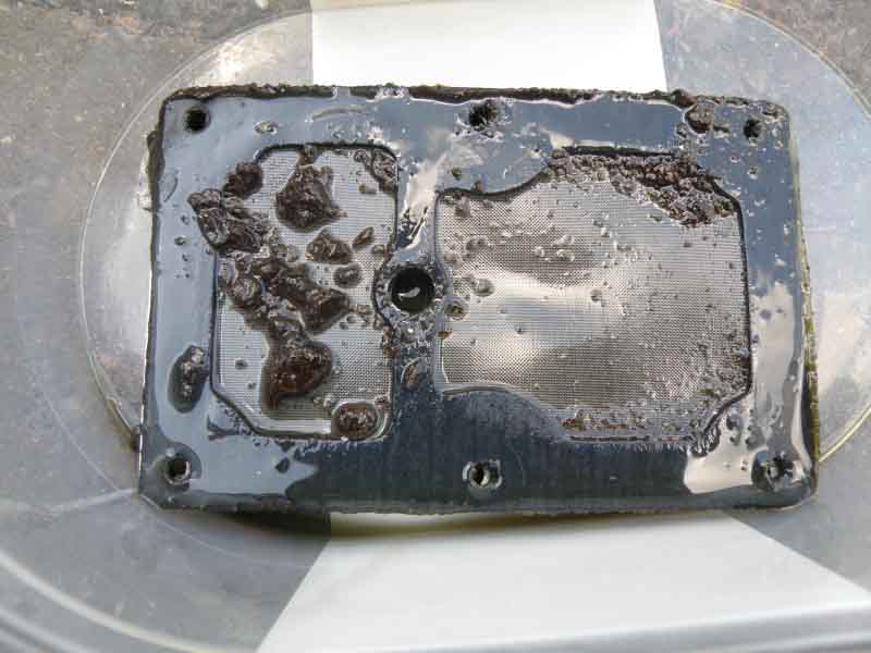 A pal has a supercharged roadster and had been having various problems with it failing to engage and disengaging once engaged. Whilst some of the problems seem to have been electrical and were fixed it was still disengaging, and it seemed to be on sudden changes of direction i.e. overtaking i.e. as if 'oil surge' was causing oil starvation. Low oil level could cause that, but of course that had been eliminated as a possibility some time previously, so he decided to do an oil change and remove the sump and filter. There was a considerable amount of what looked suspiciously like friction material lying on top of the filter - which was quite probably restricting the rate at which oil could pass through the filter into the sump to be picked up again by the pump! After a bit of pondering and discussion with Overdrive Repair Services in Sheffield it was decided the best option was to send it to them and as well as any repairs they would uprate it to V8 spec to cope with the additional torque of the supercharger. He and another pal got the engine and gearbox out as one, removed the OD, parcelled it up and sent it off. He got a nice shiny one back in little more than a week, and I was co-opted to help fit it and do an opportunistic change of the clutch, slave cylinder and slave flex hose at the same time.
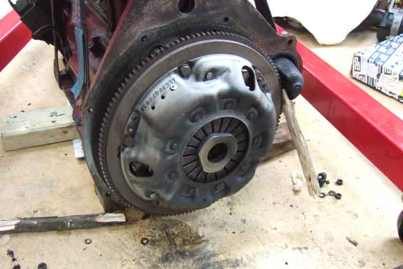 First task was to split the engine and gearbox, and the biggest problem was to support the engine partly on the hoist to stop it falling over, and partly on blocks to stop it swinging about, and support the gearbox such that as the two are unbolted there is no tendency for them to change angles in different directions and put a bending force on the first motion shaft. Really quite difficult, and having split them both ways now I would never ever contemplate removing both if all I were replacing was the clutch. Even if doing something with the gearbox, if I could get the car high enough I would still remove the engine i.e. while the gearbox is firmly attached to the car, then remove the gearbox separately (as I did for the V8 gearbox). This was reaffirmed when it came time to put the two together, as there is a limit to the amount of weight two blokes of a certain age can manipulate in four directions while trying to get the splines re-engaged, but more of that later. The crucial thing is to keep an even gap all the way round between the bell-housing and the engine back-plate, while you are separating and joining the two.
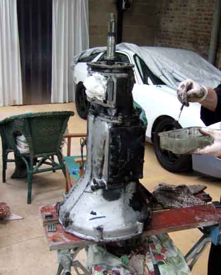 With the gearbox off we decided to go for the interesting bit first and refit the OD. For this we had a Workmate to stand the gearbox on its bell-housing so we could lower the OD onto the other end, also recommended by the people in Sheffield. They supply a gasket for the OD/gearbox join which is proper gasket material, and not the flimsy paper effort supplied by one of the major parts houses. Although the proper gasket, being thicker, will have more ability to cater for minor imperfections in the two flanges, we decide to go for belt and braces in the shape of a smear of non-setting joint sealant on both faces of the gasket.
IMPORTANT! The LH overdrive is attached to the gearbox with the solenoid and the manufactures info plate on the bottom. Unlike the D-type where they are basically on the side, which is how one MG 'specialist' used by an MGOC forum member attached an LH OD, only discovered when engine and gearbox were back in the car and he was struggling to understand how the speedo cable ran.
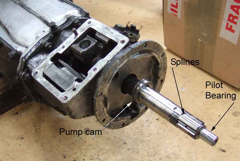 There are two aspects to be considered when fitting an OD to a gearbox. One is the splines of which more later, and the other is the hydraulic pump cam on the gearbox and the pump plunger on the OD. There is a slight chamfer all round the edge of the cam and I wondered if this would enable the pump roller to slide onto the cam as the two were pushed together if the output shaft was turned to present its lowest profile to the pump roller. Both the Leyland Workshop Manual and Haynes use the hallowed phrase "To refit, reverse the removal procedure" - it most certainly is not! I took the cam off the gearbox output shaft - be aware there is a ball bearing in a depression in the shaft which engages in a slot in the cam to drive it, make sure that doesn't fall out!! - and held the cam in the position it would be inside the OD, and it was obvious the pump shaft will have to be pulled back against its return spring at least 1/8" before the pump roller would clear the cam, more than the chamfer offers. John Twist recommends grinding a bigger chamfer on part of the cam, but I didn't think much of that idea. We used a length of braided nylon cord that happened to be handy, fed through between the pump shaft and roller, the shaft can be pulled back against its return spring pretty easily with that. The two casings will only be about 1/4" apart as the roller meets the cam, so not much space for anything else, but to make things easier it helps if the output shaft is turned so that the cam presents the lowest part of its profile to the pump roller. Easily done, but you are going to have to rotate the OD output flange to align the splines, which could easily turn the gearbox output shaft as well. So as the gearbox was on the Workmate we simply put the gearbox into a gear (any gear will do), turned the cam to the correct position, and closed the workmate jaws onto the first-motion shaft to lock the cam in position.
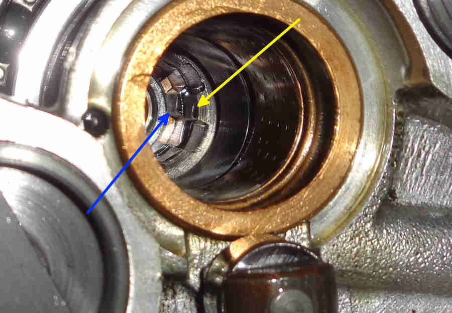 We picked up the OD and turned it open end down ... and about a cup-full of oil (presumably the residue of what was used for their testing) ran out going all over where we didn't really want it. Lowered the OD over the shaft, and it went down until the studs just started to go through the gearbox casing holes, and stopped at about a half-inch gap. We thought that might be the pump roller on the side of the cam, so pulled it back with our cord. It moved back and fore freely and made no difference to the gap between the casings, so it must be something else. Looking inside the OD there are two sets of splines, one in line with the other. One of the people at Sheffield had said something about 'moving the lower splines' which didn't make much sense at the time, especially as he qualified it with "But I only repair them, I don't fit them". At first sight they appeared to be in line, both turning as I turn the output flange, so we have another go with the same result. We then made a crude depth-gauge from a long screwdriver and a bit of masking tape to measure the distance from the edge of the OD casing to where the two splines meet, and compared that with the gearbox output shaft adding on the half-inch gap, and it came right to the end of the shaft, so the shaft must be going through the first splines, but not the second. A closer look at the two sets of splines shows that although one side appears to be in line - the side I looked at first, the other side is noticeably out of line! So a quick call to Sheffield to clarify 'moving the lower splines' and it turns out the inner set are on the one-way clutch, and if you turn the output flange one way the two sets move together, but if you turn it the other way they can move apart. They are set correctly at the rebuilders, but can move in transit, and maybe if you turn the output flange. What you have to do is put a long screwdriver down inside the splines, hold the output flange, and turn the inner set anti-clockwise relative to the outer set (they won't move the other way because of the one-way clutch) until the splines are exactly in line. There are no instructions with the OD about refitting it, I don't think it would hurt them to include something to this effect. Subsequently (with another one to refit sometime) it occurred to me that a flat bar of the appropriate width and thickness to replicate two opposing splines on the gearbox output shaft would work well as an alignment tool, measuring the shaft comes out at 1 1/8" diameter at the splines i.e. a bit less in the recesses of the OD, and each spline is 9/32" wide i.e. a bit more in the OD.
Anyway, with the splines aligned we tried again, and this time the OD stopped about 3/4" short, with the studs clear of the gearbox casing! This must be the first set of splines not aligning this time, so pure luck that they did the first twice we tried. The only way we are going to correct this is to turn the output flange, but which way so that we don't upset the alignment of the two sets!? Now if we had to turn the inner set anti-clockwise relative to the outer set to align the two sets, because it won't move clockwise, then it stands to reason that if we turn the outer set also anti-clockwise then the two sets will be locked and so not move out of alignment - OK? A quick practice in the air - anti-clockwise looking into the splines will be clockwise looking down on the flange, and I go for it. I turn the flange, then feel a tiny click, which is probably the splines almost engaging. But have I gone to far? I can't turn it back or I could misalign the two sets of splines again, so carry on turning clockwise but slowly, and feel another faint click. This time we waggle the OD a little bit, and it drops, this time with about a 3/8" inch gap. So now we pull on the cord, and bingo it drops the rest of the way - barring the thickness of the cord. So very carefully easy the OD up again about 1/8", and pull the cord out. This is where cord is probably better than wire, anything strong enough might be difficult to pull out and leave scratches.
Annoying, as with a solid shaft once fitted the two sets of splines never move relative to one another, so if they had locked them together in some way when building up the OD the job would have been so much easier.
October 2024:
And then a sudden realisation - it's extremely difficult to get them exactly in line poking a screwdriver down inside the OD, and if the inner splines are even fractionally past being in line with the outers then because of the one-way clutch the shaft has no chance of nudging them back into exact alignment. But if they are fractionally short of being in line then there is a good chance of them being nudged into line as you lower the OD onto the shaft!
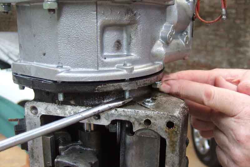 It's now just a case of putting the lockwashers and nuts on the OD studs ... or is it? Two of the studs don't have enough clearance to get the nuts under, so again we have to ease the OD up just enough to get the nuts under, but not enough to get the roller off the cam! The easiest way of doing this is to use a flat-bladed screwdriver under one of the studs and lever up carefully while lifting the OD until there is enough space on the other stud, and a couple of finger-tips to get the threads started. The screwdriver keeps the gap consistent, you don't want to drop the stud onto the nut and risk damaging the thread. With that nut started and on a few turns, lever under that one to lift the other stud and get the washer and nut on that. With the second gearbox and OD one of these nuts just slid under the stud but the other needed the lever. With those two on the other six are easy, then time for a well-earned bacon sarnie!
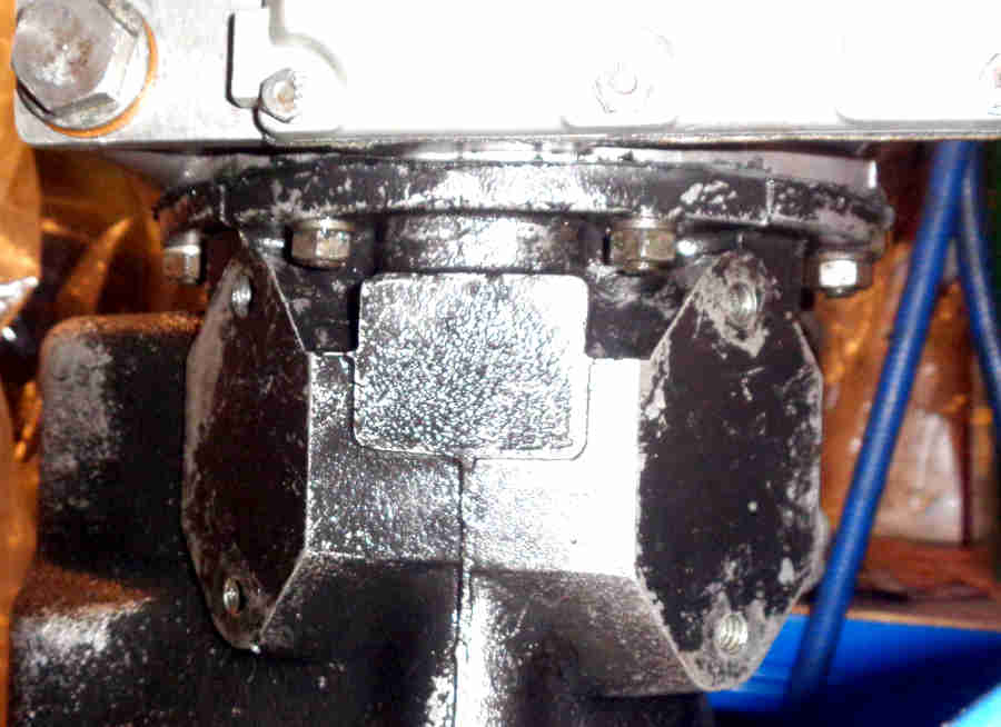 Well, I say the other six were easy, but with the second gearbox and OD two more were awkward as well being in angled recesses above where the cross-member attaches. Not only to get the nuts started, but they need a very slim 7/16" open-end spanner to get enough of a swing in the angled recesses to tighten them one flat at a time, even a slim ring-spanner won't go on. Although the first installation was on a 4-synch gearbox and the second on a V8 both use the same rear extension so just casting differences.
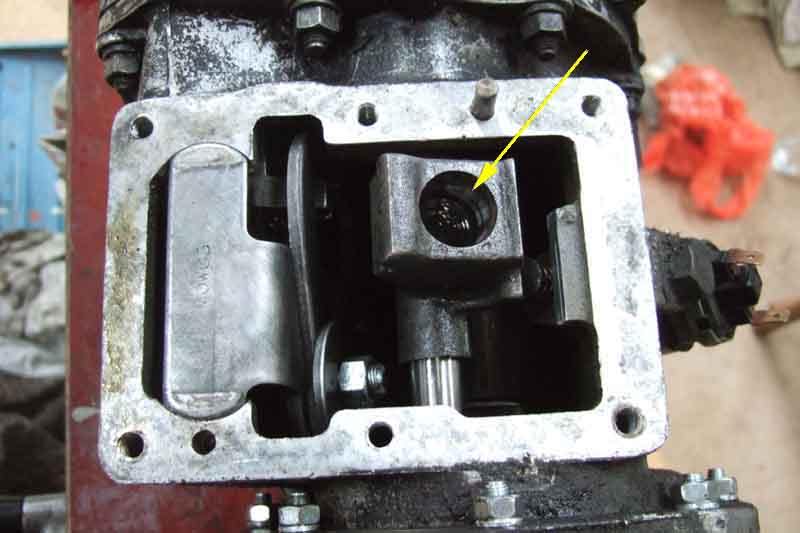 After that we change the clutch, then more struggling getting the gearbox back on the engine, keeping it square and aligned in four orientations while turning the OD output shaft (gearbox still in gear) to align the splines, reaffirming that separating and reattaching them in the car is by far the best way (short of using an engine stand). February 2018: However it subsequently occurred to me that by using, say, four long shafts or studding about the same diameter of the bellhousing bolts, long enough to engage with both halves before the first-motion shaft starts to engage, that would certainly help in keeping the two halves correctly aligned whilst pushing them together. Then refit the remote tower (which has to be removed to remove and refit the OD), and most important - attach the gearbox harness to the switches, solenoid wire and gearbox and engine bracket points before putting the whole back in the car! Final job of the day is to change the clutch slave and flex hose, the latter can be really difficult on the 4-cylinder with the engine in-situ. Reinstallation of engine and gearbox to the car is a job for next day.
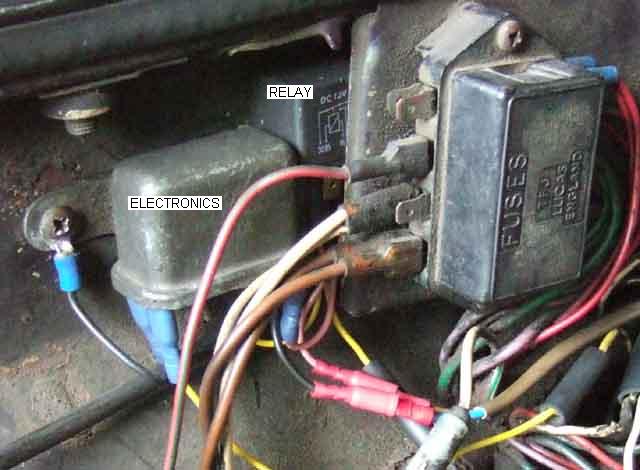
These are the details of the MkII version. For the MkI version click here, and for an 'all-electronic' version see here.
It may be my age but from time to time I find that I move from 3rd or 4th with overdrive engaged to 1st or 2nd and forget to switch overdrive off. All is well until I change up from 2nd to 3rd, then all of a sudden the overdrive engages again, usually under conditions where it is inappropriate. This means not only do I get the mild and unexpected jolt as it engages, but another one when I manually switch it off until I need it again. This has bugged me for some time and I felt sure I could knock up (i.e. build!) a circuit to prevent it.
August 2013: Following an enquiry about fitting this circuit to a car with the gear lever driver's switch I realised there are a couple of complications. For UK cars it is one of accessibility in that the circuit is inserted between the driver's switch and the gearbox switch, so you have to access those wires under the tunnel. North American cars are even more complicated, see here.
The intention of the circuit is to allow overdrive to be engaged if the manual switch is operated whilst in 3rd or 4th, but to lock it out when I change to any other gear, even when I change back to 3rd or 4th, until the manual switch is turned off and on again. On cars with OD on 3rd and 4th OD remains engaged when moving between the two, unless you move the gear lever out of the 3/4 plane into the 1/2 plane and back again, which will disengage OD and lock it out. Originally I achieved this with just one relay with a single normally-closed contact, but its disadvantage is that it requires a connection to the solenoid side of the gearbox lockout switch and there is the faint possibility that a fault could leave overdrive engaged in reverse which would destroy it. This version uses some simple electronics as well as the normally-closed relay and completely eliminates that possibility.
What happens is that the normally-closed contact of the relay is wired in series with the gearbox and manual switches. This means that if any of the manual switch, the gearbox switch, or the relay contact are open overdrive is disengaged, and they all have to be closed before overdrive will engage. Thus it is fully fail-safe - any fault in the additional circuitry can only cause the OD to either operate exactly as the factory intended, or not at all, it can never cause it to operate when it shouldn't be i.e. when reverse gear is selected. So as long as the relay remains released the overdrive operates completely normally, but when the relay operates it prevents the overdrive engaging regardless of the state of the gearbox and manual switches. The circuit is such that if the manual switch is closed and the gearbox switch is open then the relay will operate, and will remain so until either the manual switch is opened or the ignition is switched off. Remember that whenever the relay is operated its normally closed contact is open, and this prevents the overdrive from engaging.
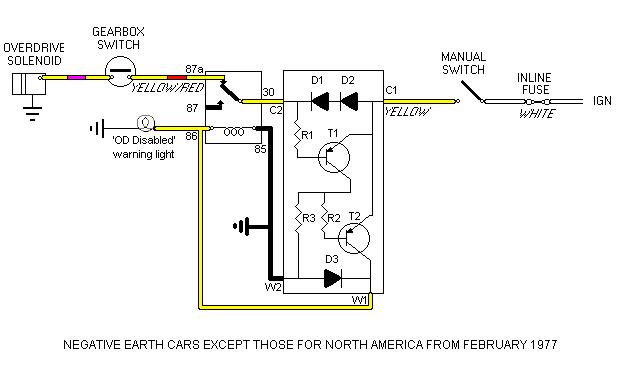 If you look at the diagram you will see that with the manual and gearbox switches closed and the relay released the solenoid operates in series with the two diodes, D1 and D2. Semi-conductor diodes exhibit a small volt-drop when forward-biased, and though this is not enough to affect the solenoid the voltage developed across the two in series is used to forward-bias transistor T1 via resistor R1 and so switch it on. T1 switched on ensures that transistor T2 is switched off by connecting emitter potential to its base via R2. T2 switched off means that the relay is released, so maintaining the status quo, and overdrive engaged.
If the gearbox is taken out of an overdrive gear the gearbox switch opens, the solenoid is disconnected and overdrive switches out. At the same time the current ceases to flow through diodes D1 and D2 so there is no longer any volt-drop across them. This causes transistor T1 to switch off, which allows transistor T2 to switch on via resistors R2 and R3. Transistor T2 operates the relay which puts another break in the circuit to the solenoid. D3 acts as a 'spark quench' diode to prevent high-voltage back-emfs from the relay from damaging transistor T2 when it switches off and releases the relay. Even if an overdrive gear is selected again and the gearbox switch closes, the relay contact ensures that the solenoid is not energised, so there is still no current flow through diodes D1 and D2, so again the status quo is maintained and overdrive remains switched out.
It is not until the manual switch is turned off, or the ignition is turned off, that the sequencer relay releases, because there is no longer the 12v supply via transistor T2 to keep it operated. But this also means that even when the relay releases there is no voltage supplied to the solenoid so overdrive remains switched out.
Only when the manual switch is turned on again in an overdrive gear does current flow through diodes D1 and D2, the sequencer relay contact (closed), the gearbox switch (closed) and the solenoid to switch overdrive in again.
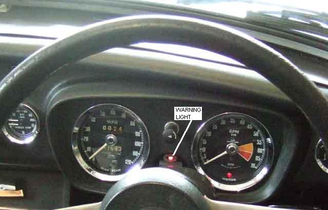
There has been some discussion about having a warning light glowing when overdrive is engaged, but with the dash and gear lever switches there doesn't seem much point as it is easy to see and feel whether it is on or off. Less easy with the column switch, and in fact my V8 (column switch) came with a warning light courtesy of a PO. But on the roadster with the sequencer relay there have been a couple of occasions I wasn't sure if overdrive was engaged or not, even though the manual switch was on, i.e. I can't tell if the sequencer relay has operated and locked it out without turning the manual switch off and on again. So an enhancement is to have a warning light that glows only when the sequencer relay has operated i.e. overdrive is manually selected but locked out.
Electronic components: I used some 100v 1A diodes (from Lucas, believe it or not) and 50v switching PNP transistors I happened to have lying around from my Telecom days 25 years ago. The resistors used will depend on which transistors you use, but they are not critical. I think I used 1k ohms in each case selected to give minimum current but reliable operation of the circuit. I mounted the components on a small circuit board such that it could be fitted inside an old Lucas metal can 6RA relay, utilising the spades on the insulated base plate (winding and contacts removed) for its connections to the outside world. The warning light is a red (red being significantly brighter than the green and yellow examples I had in my box of bits) LED in series with a 470 ohm resistor, the pair being connected in parallel with the relay winding, so that whenever the relay is operated the LED glows. Updated September 2010: The relay is a 12v automotive 'changeover', 'single-pole double-throw' or 'SPDT' type (try Googling '12v SPDT auto relay') with five spade terminals - a normally open (87), a normally closed (87a) and a common (30) as well as the two winding terminals (85 and 86), check the diagram on the relay matches up with type S4 here. Note that the circuit includes a protection diode (D3), if using relay type S6 you won't need D3 but must get the relay winding terminals 85 and 86 the right way round or you will blow the transistor. Relay type S5 includes a protection resistor, on its own that may not be enough to protect the transistor, and may alter the parameters of the circuit so is best avoided.
Update October 2010:
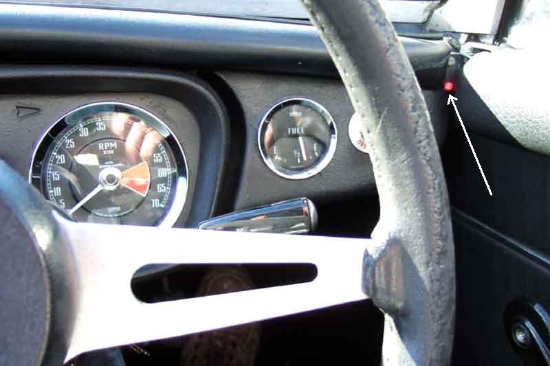 After realigning the steering and rack columns I find the warning light has moved from being just visible to just invisible, unless I keep leaning forward which is a pain, so a new position has to be found. I settle on the small gap between the end of the crash rail and the door seal, as shown here, which is conveniently near the dash-switch.
Differences in other years and markets:
Testing:
Overdrive - How many were there? Added January 2008
| Period | Market | No OD | OD | Total | Percent OD
| Aug71-Nov73 | Home and | non-North American export 5201 | 22240 | 27441 | 81
| Nov73-Sep74 | Home and | non-North American export 434 | 7123 | 7557 | 94
| Sep74-Oct80 (OD standard for | Home market from June 1976) Home and | non-North American export 813 | 40087 | 40900 | 98
| Total Home and | non-North American export | 6408 | 69450 | 75898 | 92
| Aug71-Aug72 | North America | 19390 | 2650 | 22040 | 12
| Aug72-Sep74 | North America | 37993 | 6449 | 44442 | 15
| Sep74-Dec74 | North America | 5300 | 1403 | 6703 | 21
| Dec74-Aug75 | North America | 9260 | 1593 | 10853 | 15
| Aug75-Jun76 | Canada | 996 | 313 | 1309 | 24
| Jun75-Jun76 | USA | 14700 | 3408 | 18108 | 19
| Jun76-Oct80 | USA (not California) | 50883 | 10324 | 61207 | 17
| Jun76-Dec79 | California | 11958 | 4483 | 16441 | 27
| Jun80-Oct80 | Japan | 0 | 805 | 805 | 100
| Aug76-Oct80 | Canada | 3458 | 1176 | 4634 | 25
| Total North American spec | | 153938 | 32604 | 186542 | 17
| |
At 92% with overdrive for the Home and non-North American export market and only 17% for North American spec there is indeed a huge disparity. And why should Japan get 100% with OD (admittedly on a very small number) when they got the North American spec towards the end of production? Even California and Canada got a significantly higher proportion than the rest of the USA.
Update April 2008: I've just come across the following passage in 'MG by McComb' (p197): "Another special problem on the US market concerned the MGB overdrive, which had been available from early 1963 but for some time was withheld from America - where it was most needed - because it might adversely affect the already dwindling sales of the big Austin-Healey. Eventually commonsense prevailed ...". There is no indication of how long this withholding lasted or when overdrives started to be supplied, but with the Healey 3000 finishing in 1967 the very low take-up in North America still continued to the end of production in 1980. Subsequently a USA pal said generally people there didn't know what overdrive was, so couldn't see the point of paying extra for it. It is certainly highly desirable now, with rarity resulting in very high prices so much so that it is worth shipping cheap units from the UK.


