


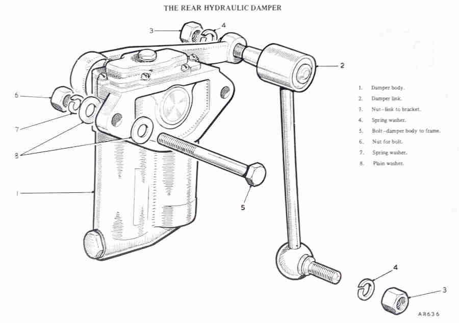
Rear
Damper Fluid
Topping-up
Replacements
Internal valving
Telescopic/tubular Dampers
However as far as overall suspension design goes the very detailed 'The Rover Group, Company and Cars, 1986-2000' by Mike Gould (a gift from my local postie with 'MGB, The Complete Story' another very detailed book) describes how the Rover 800 based on the Honda Legend suffered from Honda's insistence on wishbone suspension which resulted in a hard ride, saying that strut suspension would have allowed more travel and hence more comfort. The reason for that is that with wishbone suspension the wheel and hub move in an arc, whereas with strut it's in a straight line, retaining steering and suspension alignment over greater travel. If you had anywhere near that travel with wishbones the alignment would change massively over the full travel unless the wishbones were pivoted in the centre of the car as some 'modern' rear systems are.
Lever-arm dampers are hydraulic (being filled with light hydraulic jack fluid, not oil as such). The usual failure mode of these is for the seals on the shaft that the arms connect to start leaking. Once that happens they are shot, there is no point putting more fluid in, it will just leak out again. A leaking damper can be an MOT (UK annual inspection) failure point in the UK if the tester suspects or finds it is affecting damping. Other than that I have never found any need to check and top-up the dampers, even though it is a routine maintenance item.
Before paying for replacement dampers (i.e. ideally get them on a personal visit to the supplier) check they move smoothly and are heavily damped through their full travel and back to the centre, then wiggle the arms up and down near the centre and make sure there is no slop as they change direction. Exchange dampers where you return the old one is much cheaper than buying new, and the rebuilt replacements are usually of reasonable quality. But as the rebuild is only as good as the original it is possible to get a duff one that fails after quite a short period, however it is still much cheaper to have to change it again fairly soon than to buy new. Out of three replacement lever-arm dampers I had to change a rear one for a second time after only a year or so, its replacement and the other two have been fine. At the time of writing I have just replaced another one so the jury is still out on that. Update October 2009 Annoyingly that started weeping after a year or so, but lasted a further couple of years and MOTs before it got bad enough to start dripping on the floor, which was when I changed it again. Hopefully better luck this time. 2018: Another front replacement on Vee due to my own error (don't ask) but all the others (both cars) fine so far, apart from an advisory of 'light misting' on Bee's near-side rear in 2019, not replaced until 2023.
Stevson Motors in Birmingham were often mentioned as a good rebuilder of customer's own units, but could take a while. However I understand they no longer do that, only fuel, brake and oil hoses, pipes and unions, which I have used them for including one-offs to my design.
November 2023 Another mentioned just this month in MG Chat on the MGOC forum (passed on to me by Michael Beswick) is Vintage and Classic Engineering near Bala. The original poster said after a long discussion he is satisfied that they do a proper refurb and not just a 'paint and despatch', and another poster said he had used them himself earlier in the year. Again customers own units (although they do have some in stock), so a time delay involved as well as double postage (unless you are nearby).
T H Brearley writes on the MG Enthusiasts forum regarding replacement rear units:
"In the spirit of improving the sum of human knowledge, this is what I found. With each damper clamped upright in a vice a 10lb weight (e.g. sledge hammer head) took the following times to pull each lever from the top of its range to the bottom:
"Old N/S damper 6.5 secs
"Old O/S damper 5 secs
"New N/S damper Infinite (it never reached the bottom)
"New O/S damper 28 secs"
And subsequently posted "I should have said that the O/S damper moved slowly through the first 2/3 of its stroke before stopping. It could be pushed all the way down with a firm hand." I think he means the N/S.
Then Dave O'Neill posted:
When I fitted adjustable valves in the V8 rears I removed them complete with drop-links and bottom plates as being easier. Held in a vice the weight of the link and plates was enough to pull the arms down slowly, but I didn't bother timing it. For the other direction I have a spring balance and pulled up with that showing as close to 15lb as I could keep it. The original valves gave 9 secs and 10 secs, the adjustable on minimum gave 6 secs and 8 secs i.e. a 25-30% reduction. Turned harder half-way gave 16 secs (I didn't bother going any harder!), so they are very much biased towards making the suspension harder. But on the road at minimum they very definitely make the ride more to my liking.
Personally I've never - unlike telescopics - had lever-arms go soft, only leak. I've never bothered to do any more than check them (rebuilt) on the suppliers bench as above - one of the benefits of having a good supplier reasonably close to home.
Front replacement: Updated October 2009
 When changing a front damper for the first time you will almost certainly need a new upper link special bolt, nut and bushes, as each one I have done has had the pin corroded solid with the inserts in the bushes. In both replacements I have done the link bolt was supplied with a Nyloc nut instead of the original low-profile castellated nut and split-pin. In neither case was the bolt long enough - or the nut low-profile enough - to be fully tightened - with a Nyloc nut there should be about three threads clear of the bolt, but the bolt barely reached the Nyloc let alone go through it. Fortunately the bolts were drilled for a split-pin and I had a suitable low-profile castellated nut in each case. Do not use a Nyloc nut without there being at least three threads visible with the nut fully tightened, the bolt could come out in use.
Raise the front of the car by jacking under the rear edge of the cross-member (if you jack further forwards than that it will slide further forward in a series of sudden and noisy movements which is a bit disconcerting. Place axle stands under the outer edges of the spring pans, and lower the jack just enough to lift the damper arms off the rebound rubbers. It is important to do this otherwise when you remove the top link bolt the axle assembly and hub will shoot downwards as they are under significant spring pressure.
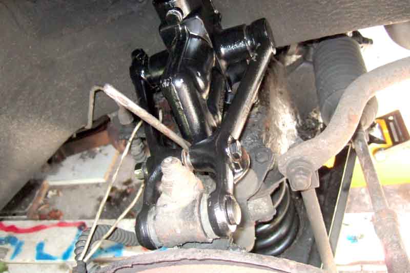
Next comes removal of the top link bolt connecting the damper arms to the swivel axle. Easy to say, much harder in practice. The bolt runs through the arms of the damper and steel sleeves in the rubber bushes. It is a snug fit in both and unless it has already been replaced fairly recently or was assembled using Waxoyl and copper grease it will almost certainly be well rusted to both. The rubber bushes will probably also have deteriorated and be bonded to the eye in the swivel axle. In two replacements on may cars this has been the case and I have had to hacksaw through the bolt both sides of the swivel axle eye. On a second replacement of one of them everything came apart very easily.
Remove the nut on the end of the link pin, it is usually castellated with a split-pin. Slacken right off the clamp-bolt holding the two arms of the damper together, and drive a wedge between them to lever the arms apart and give you more room to cut through the link bolt.
Use a length of cable or whatever to tie the swivel axle to the bracket of the bump and rebound rubbers to prevent the axle falling outwards and stressing the brake hose when the link pin has been cut through or removed.
You can try driving the link bolt out of the bushes and arms, but it shouldn't take much hammering to realise it isn't going to shift. If not, cut the flange off the end of each bush by chiselling and cutting at an angle into the eye of the swivel axle. This reveals a section of link bolt on each side to cut through without damaging the inner faces of the old damper (which might then be rejected as a core replacement) or the swivel axle eye. Use a hacksaw where you can turn the blade at 90 degrees to the frame and this should allow you cut inwards and upwards each side. With a decent blade it shouldn't take many minutes to cut through both sides, and the damper arms can be lifted up from the swivel axle eye. Remove (it really should be that easy) the four bolts securing the damper body to the cross-member. I use a universal joint between the ratchet and socket, it gives that extra depth for all four bolts and a bit of angle for the back ones where the inner wing curves over them. Lift the damper away - it is heavy!
Now you have to drill, cut, twist and hammer the old bushes and remains if the link bolt out of the swivel axle eye, they will probably come out as a single piece, which can only be done if you have previously removed the flange from the bushes as previously described. Remove any lumps of rubber that are stuck in the eye as this will make insertion of the new ones more difficult.
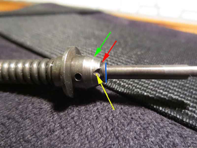
 Check the fluid level in the damper now, it's easier. If you find you have to add a lot, or in any case after transportation where they may have been at a different orientation to when fitted to the car, work the arm up and down it's full travel several times to expel any air from the valves. Remove any dirt or grit from the cross-member where the damper will sit. At this point I put a bit of copper grease into each hole in the cross-member, then put the damper in position. Coat each bolt with copper grease and insert just a few threads, don't tighten them any more than that until all four bolts are started. Again slacken the clamp-bolt holding the two arms together and wedge the arms apart to fit over the bushes. This is necessary when leaving sound bushes in the swivel axle, not just for new ones.
Coat the outside of new bushes and the inside of the swivel axle with Waxoyl and insert the bushes. They will probably be much wider than the gap between the damper arms even if they are wedged apart. You can either put one or more large nuts over the threaded end of the link bolt then tighten its nut to squeeze the bushes fully into the eye or use a small sash-cramp or something similar. Eventually you should be able to get the bushes far enough in and the damper arms far enough apart to fit the two together, but before you do so put some copper grease inside the steel sleeve of each bush, wiping off any excess from the rubber.
Place the damper arms over the bushes, put more copper grease in the holes in the arms and on the link bolt. Tap the bolt through the appropriate damper arm the bushes, and the other damper arm. Note that the bolt has a special round head with one flat which engages with a recess on one damper arm. This is the front arm on the right-hand side, the rear arm on the left, therefore the bolt can only go in one way each side. Things might need a bit of wiggling about while you are tapping to get everything lined up.
Note where the split-pin hole is in the bolt and fit and tighten the nut (40ftlb). This has to clamp the damper arms onto the ends of the bush sleeves, and the inner ends of the bush sleeves together, so it does up tight. The final position of the nut should allow insertion of the split-pin, of course. Refit and tighten the damper arms clamp bolt (28 ft lb). As the four mounting bolts allow a little wriggle-room for the damper now is the time to use it to try and correct any tendency to pull to one side or the other on a flat and level surface (note a normal drainage camber will cause the car to pull to the kerb side slightly). Pulling to one side or the other is caused by unbalanced camber, not by tracking as many think. Which ever side the car pulls there is more camber that side than the other, so pushing the damper arms forwards as you tighten the four bolts (43-45ftlb) will tends to reduce it, and pulling the damper arms backwards on the other side will do the same. It may not do much but is worth a go while you are at it. Refit the wheel and away you go. Inspect the new damper from time to time in the early days just in case you have got a duff one, and always before an MOT.
Rear dampers: August 2009
The damper, drop-link, rebound rubber and bump-rubber pedestal (and for that matter spring) must be treated as a set for correct and safe operation of the rear suspension and these vary from model to model. Whilst the damper obviously controls the rate of spring compression and expansion through the normal working range, the compressed limit is controlled by a pedestal on the axle hitting a bump-rubber under the floor, and the expanded limit is controlled by the rebound strap which is fixed between a body and axle. The final component is the drop-link between damper arm and spring/axle assembly. In an ideal world the spring, in it's normal working position, will position the axle about mid-way between the fully compressed and fully expanded positions, and the drop-link length should be such that the damper is also about mid-way in its travel. The loading on the car could be a little as a single occupant, or it could be two people plus tools and luggage with the consequent compression of the spring, so maybe a median between these two is chosen by the designer as the 'central' position. Whatever, it is vital that the drop-link, rebound strap and pedestal are installed as a set so that it is the rebound strap and bump rubber that provide the limits to axle movement and not the damper itself. Get these wrong and the damper will suffer damage. In theory it doesn't matter as much if the spring varies in set or hardness, as the other components will limit axle travel regardless and so protect the damper. But if the spring is too soft or flat you will be hitting the bump rubbers over relatively small bumps (been there, done that, extended the shackles) or at the other extreme the car will have a very tail high ("submissive monkey") stance and be hitting the straps relatively easily. Whilst hitting the bump-rubbers is merely uncomfortable, continually 'hitting' the rebound straps will eventually break them, and then you will start hitting the damper limit and damaging that.
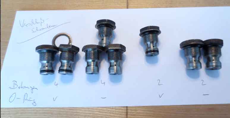
Chrome bumper 4-cylinder cars had one set of drop-link, rebound strap and pedestal, chrome bumper V8 had a different set, and all rubber bumper cars had a third set in this case the same for 4-cylinder and V8. It's well known that chrome bumper V8s had a higher ride height to 4-cylinder chrome bumper cars to improve the exhaust to ground clearance utilising a different front cross-member that was later commonised to all rubber bumper cars. The rear spring hangers were lowered at the front and the rear on all rubber bumper cars i.e. 4-cylinder and V8, hence all rubber bumper cars have the same damper and axle movement limiting parts, even though the V8 springs are harder. What is less well known is that they differed between chrome bumper 4-cylinder and V8 cars as described here. The combination of parts for each model from the Parts Catalogue is as follows:
Peter Caldwell of Wisconsin posted the following information on the MGCars BBS as part of a thread on this subject in December 2006:
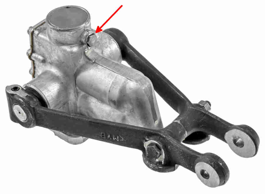
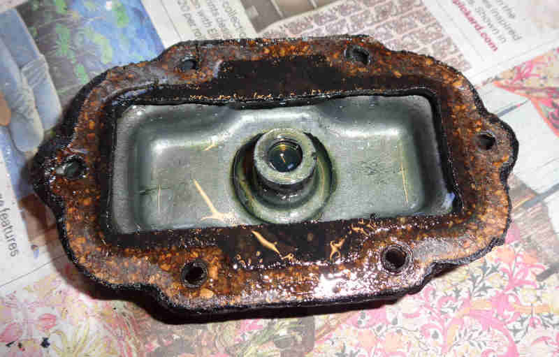
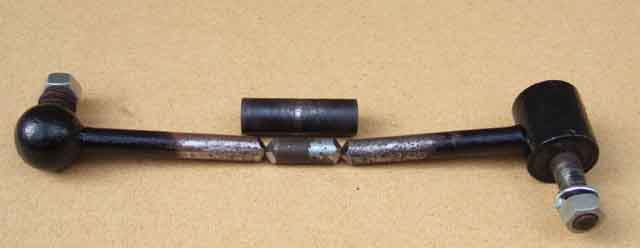
Replacement: Ostensibly two bolts and three nuts, but it can still be a bit of a bear to remove. If you haven't changed them before the drop-link nut (11/16") will likely be corroded to the drop-link pin in the damper arm, and nut and pin will turn as one, either that or the nut will come undone but the tapered pin will be seized to the damper arm. Heat not advisable due to the rubber bush in the drop-link. Fortunately it is easy to remove the damper complete with drop-link and bottom plate and deal with them on the bench. Note that the Leyland Parts Catalogue indicates that the damper bracket fits directly against the lower spring pad by stating that only two spring-locating plates are fitted per car but four are fitted - two against the upper spring pad and two against the lower.
Important - chock the front wheels. Slacken the road wheel nuts a smidgen before raising the rear wheels off the ground if the handbrake isn't up to much. Jack under the diff and put axle stands under the springs immediately forwards of the U-bolts. This is necessary to keep the springs compressed otherwise you will not be able to pull the damper plate down off the U-bolts, if the springs are extended the damper lever arm will be almost fully down. Remove the road wheel. Remove the nuts (11/16") and spring washers from the bolts (5/8") holding the damper to the chassis rail, turn the bolts to free them up, but leave them in-situ for the moment.
November 2023:
Undo the U-bolt nuts (9/16" deep socket makes life easy), and pull the damper plate down off the U-bolts. Pull the damper complete with bolts back from the chassis rail (or support the damper and pull the chassis rail bolts back to release it) and lower the whole assembly down and away from the car.
With a rusted drop-link nut I had to hacksaw at an angle part-way through the nut then chisel the cut open to free the nut. Because the pin had been turning in the damper arm this came out relatively easily. Where the nut came undone leaving the pin stuck in the arm I fitted one of the chassis rail nuts to the pin so it was flush with the end of the pin to spread the load (drop-link nuts are Nyloc), then with a lump-hammer behind the arm whacked the end of the nut and pin with another biggish hammer a couple of times and it popped out.
Check the fluid level in the new dampers before fitting. If you find you have to add a lot, or in any case after transportation where they have probably been lying down, work the arm up and down it's full travel several times to expel any air from the valves. With the top-fill arrangement of the rear dampers leave 1/2" air-gap between the bottom of the threads and the fluid.
If you removed the damper, drop-link and bottom plate as an assembly then assemble them again before fitting, use copper-grease on the drop-link pin and threads, but don't tighten the upper drop-link nut at this stage.
If you can get the damper up against the chassis rail with the bolts fitted from that side then do so, you can get more torque on the nuts if they are in the arch. However with the Ron Hopkinson rear ARB if there is not enough room the bolts have to be fitted from the arch side, and the limited room makes getting a torque wrench and socket on the nuts difficult if not impossible when the nuts are on the back of the damper.
As for removal the spring needs to be partially compressed i.e. with axle stands immediately in front of the U-bolts in order to get the damper plate underneath the spring. Fit the damper plate onto the U-bolts, making sure the spring pad and locating plate are already in place, and the U-bolt nuts. Tighten all nuts - 55-60 ft lb for the damper to chassis rail nuts, if these are not fully tight they can 'knock' over bumps. For damper-plate nuts use your judgement as they are compressing rubber pads and will only tighten gradually. Recheck after a few miles. With the weight of the car on its suspension (i.e. axle stands still under the springs) the upper drop-link nut can be tightended i.e. with the drop-link in about the middle of its travel. If the axle is hanging down the upper rubber bush could tear when the suspension goes into full compression.
Hydraulic Damper Fluid Added November 2009
As well as what fluid to use in both there is further scope for argument over fluid level in the rears, believe it or not. The Workshop Manual simply says "fill to the bottom of the filler plug hole". But some say it should be half an inch below it on the rears to allow an air space to absorb up fluid expansion on heating up, otherwise it could be forced past the seals. But if that is correct, why doesn't the manual say so? I then started thinking about the positions of the filler plugs, and realised that with the front damper filler plug on a vertical face of the damper body, filling to the bottom of the hole will still leave a significant air-space above it. But the rear dampers have the filler plug on top, which may not unless there is an air-space under the lid i.e. above the bottom of the filler plug hole. When I converted Vee from telescopics back to lever-arms I bought a 'kit' containing dampers, drop-links and bottom plates second-hand from some unknown MG at Stoneleigh, and it was only when I decided to recheck the fluid level some time after fitting them that I discovered the filler plug hole was also on a vertical face, and not on top as they should be! "Ah ha", I thought, that would leave an air-space in the rears as well, and maybe that part of the manual had been copied from that for another vehicle where both front and rear filler plugs are on a vertical face. But looking again in the manual not only does it show a top-fill rear damper, with instructions to remove the plastic plug in the chassis rail to access it, but it also shows the front damper with a top-mounted filler-plug! So from there being an obvious air-space above the fluid on both types, there could be none on either. When Vee's rear dampers started leaking (after having lasted a few years, I was quite prepared to change them at the outset as they were an unknown quantity) I got the correct top-fill ones of course, and checking the level before fitting found that it was indeed about half an inch below the bottom of the filler plug hole. So that's good enough for me, and having found with leaking dampers that the fluid level can drop a long long way before it affects damping, leaving a half inch gap below the bottom of the filler plug hole on the rears is neither here nor there, and at least you are sure that there is then a clear air space, if that makes a difference.
Fixed:
Sven
Armstrong catalogue BL catalogue Drop-link Length Rebound strap
4-cyl chrome bumper 8178LH/RH GSA168 LH 169 RH 97H 2031 8.5" AHH 6355
V8 chrome bumper 10801LH/RH GSA328 LH 329 RH 37H 8075 9.75" BHH 989
4-cyl rubber bumper
to 7612012LH/RH GSA368 LH 367 RH 37H 8778 10.5" BHH 989
V8 rubber bumper 12012LH/RH GSA368 LH 367 RH 37H 8778 10.5" BHH 989
4-cyl rubber bumper
77 on12075LH/RH GSA368 LH 367 RH 37H 8778 10.5" BHH 989
"Per Armstrong's 1978 USA catalog... 8178 fit all B and GT (4 cyl) through 1974 (The 73 and 74 BGT V8 used 10801 which I've never seen). All models 75 through 5/76 used 12012. Then all models 6/76 to end used 12075. Again, I've seen absolutely no difference in the 8178, 12012, 12075. I suppose if matching, check that the numbers are the same."
 Bee has the bolts going through the damper and the nuts and spring-washers inside the arch, but Vee has the bolts fitted from the arch side, both always like that in my ownership. However the Leyland Workshop Manual drawing shows the bolts going through from the arch side and nuts and washers against the damper. That way means you either use a spanner (limited leverage) on the nuts on the back, and they are very tight at 55-60 ft lb, and fitting washers and nuts in limited space, or a socket and breaker bar (maximum leverage) on the heads in the arch which means breaking the torque of the nut plus any seizing of the bolt in the chassis rails. Reversed means the socket and breaker bar is only overcoming the torque of the nuts, but the damper must be removed and offered up with the bolts already in the damper. You also need to be sure the bolts aren't long enough to foul the tyres. If the bolts have seized in the chassis rails (copper grease!) then you are probably snookered in either case as there is insufficient room to get the damper off the bolts when they are fitted from the arch, and if from the damper side then the damper will be stuck fast anyway.
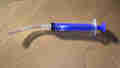
 Front dampers on the MGB are side-fill with a combined filler and level plug, but need a syringe with a short length of tubing to get the fluid in. Push the tube in at least an inch and push fluid in until it trickles out. Rear dampers are top-fill under plastic plugs on the rear shelf by the battery cover and the same syringe is useful for these as well, remember to block the end of the tubing with a finger-tip to prevent drips on paint-work as with brake and clutch.
 But then replacing Vee's damper valves with adjustable ones the process involves removing the 'lid', and the underside of that has quite a large space above the bottom of the filler hole, i.e. an air space.
 As far as getting fluid into them is concerned whilst dribbling fluid in to the top of the rear dampers is possible with great care the side filler on the fronts is another matter. But an 'oral medicine fluid syringe' and short length of screen washer tubing makes both a doddle. Don't get it mixed up with little Johnny's though, and don't let it drip on paintwork, it's as bad as brake fluid!
Adjustable
Hi Peter,
I'm Sven from Germany and I'm restoring an MGB GT and converting it to electric drive. I write to you because I cannot find information on the setup of the Armstrong shock valves, and in this forum you are referred to as being the specialist on these. There is nobody here in Germany and Europe who can tell me which are the exact parts for original front and rear shock valves. Disassembling several valves revealed different setup for left and right shocks even for reconditioned pairs fresh from the counter... Let me give you a short overview:
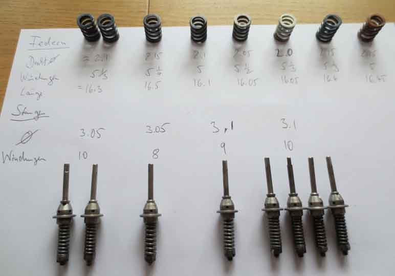
Sven, There ARE different valve designs that vary by the generation of casting by Armstrong. Remember, the same design was made by Armstrong from 1962-1990. There were many small differences in the valve as determined by the small changes in the castings. We hope that Armstrong made the valve changes based on damping characteristics they could test on a dyno. I can't tell you what should be in the castings you have, but I CAN tell you not to over think this. It doesn't make a huge difference from a street driven perspective. We do make an externally adjustable shock that may interest you as you try to find the best spring rate for your application.
Peter
Hi Peter,
And thanks for your quick reply. Your statement 'It doesn't make a huge difference from a street driven perspective' helps a lot, because with my EV conversion I will drive 95% in the city and the top speed will not exceed 110 km/h. So I'll just keep an eye on assembling the right hand valve identical to the left hand valve.
Thank you again and best regards,
Sven
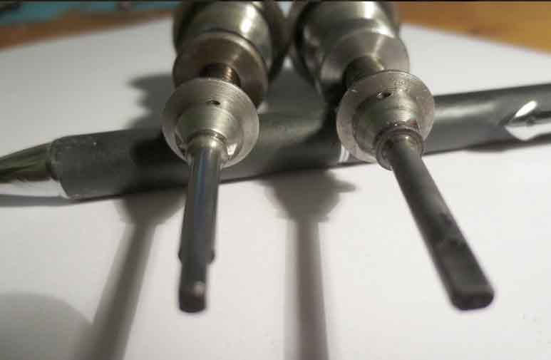
You want to be sure that the main valve body, the part with the hex nut, is correct for the casting. 1 takes an o-ring with washer, and 1 without. There is a depth difference, too.
Good luck. Peter.
Okay, so I will also have a close look at the cast bodies of the shocks...
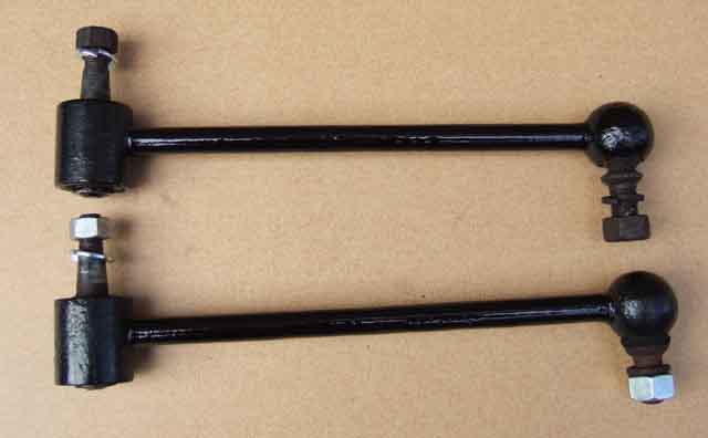
The replacements lasted for many tens of thousands of miles (no more than one should expect) but I had been aware for a while that the ride was getting quite bouncy, especially over humps and dips. The USP of the Spax is their adjustability, but unless you have them on the softest setting they give a bone-jarring ride, and many testify to this. Thinking that they may have 'softened up' over the 70k or so miles they have been on the car (which itself is a poor 'feature') I tried turning the adjusters, but needless to say they had seized, and I decided that I would not replace them when the need next arose but go back to lever-arms. However I was concerned that if one should fail, unless I splashed out again for a replacement (or possibly a pair), I might have to take the V8 off the road for a time while I sourced a pair of lever-arms together with the drop-links and bottom plates. So at the 2006 Stoneleigh MG Spares Show I was on the lookout and managed to pick up the whole lot minus one bottom plate for a tenner, and got a used bottom plate from elsewhere for another fiver. They were already assembled but I wanted to part them for cleaning and painting, but as usual (IME) the nuts had seized. TIP: Careful hacksawing as far as I could through the nut without cutting into the studs (OK, I just nicked the threads, but that won't affect its strength) then using a cold-chisel to open up the cut cracked the rust and it came undone. Using heat is inadvisable is it is bound to damage the rubber bush the stud is mounted in, which is not a replaceable item. That left me needing a couple of nuts, which being Imperial are not that easy to come by. Popped down to my local Halfords where the chap who usually MOTs all my cars had a root through his toolbox and came up with exactly what I needed (That's another pint I owe you ...).
 I then discovered that despite measuring two lengths of drop-link at the show, and thinking I had got the longer V8/rubber bumper items (10 5/16" pivot pin centre to pivot pin centre, thanks Graham), I actually ended up with the shorter CB items (8 3/4"). Only discovered this as part of an email thread with someone else, who had the longer ones and needed the shorter! Sadly he was in America so a swap was out of the question. Rather than buy another pair I decided to try 'cutting and shutting' them to extend them (as I had with the rear shackles on the roadster) by the required 1 1/2" or so. Looking round the garage I found a couple of front suspension bottom trunnion bolts that were the correct (0.5") diameter and did the necessary cutting and welding. Two coats of Hammerite smooth on them and the bottom plates and they were ready to go on.
I was quite surprised to find the U-bolts and the nuts and bolts holding the top brackets to the chassis all came undone quite easily as they had not been touched in my ownership, likewise the replacements went on straight-forwardly, the whole job only taking a couple of hours. TIP: The only thing to be aware of is that the two bolts holding each damper to the chassis rail are different in length by about 1/4", which could cause you some head-scratching if you get them mixed up and the two shorter ones on the same side. At some point the forward bolt was recessed into the chassis rail to give more clearance for tyres, possibly for the wider tyres on GT and V8, the shorter bolt goes in this position.
Took the car for a test drive and immediately noticed that on 'normal' surfaces the ride seemed exactly the same but over humps and dips there was no bounce, just a more appropriate firmness without harshness. The standard lever-arms have a two-stage valve that gives relatively mild damping with short movements and harder damping with larger movements, something I have never seen attributed to telescopics of any type. I was deliberately taking the car over as many speed humps as I could find, and going at them progressively harder, when I actually broke one of the welds. It was my fault, when doing the first one I became aware that I was feeding the wire too quickly, which tends to form bobbles of weld on the surfaces of the two pieces being joined rather than fusing them together. No matter, 1/2 hour to take the broken drop-link off, clean up the joint and re-weld, but this time I slipped the spacer tube from the aforementioned bottom bolt (exactly the right internal diameter) over the shaft first, then welded the shaft, then positioned the spacer tube so it covered both welds, and applied more weld between spacer and shaft. Repainted, refitted a couple of days later, and so far so good.