


Ride Heights Spring Specs Front Springs Rear Springs
Secondly the article says that CB V8s had the lowered rear spring rear mounting point and the front mounting point only changed with RB cars. However I have found different.
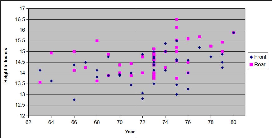
The accepted method of measuring and comparing ride heights is from the centre of the axle to the bottom of the bright trim strip running the length of the car, and this removes any effects of wheels and tyres. The car should be sitting on its wheels on flat and level ground, and be fully fitted out i.e. ready to drive off. Missing major components particularly engine/gearbox will of course allow a car to sit higher and will not be valid, even more so if the car is on a rotator (it has been known ...)!
Converting RB to CB
Following a question on the MG BBS the information on ride heights below was posted, all measurements are taken from the centre of the hub to the bottom of the chrome strip. If you would like to add to this resource please mail me with your year (state CB or RB if 1974), Roadster/GT, measurements, and any notes regarding age/mileage of springs, departure from standard etc.
Note: It may seem obvious but the static ride height of a car depends on how much weight is on the suspension. Take the engine, gearbox and seats out for example and you remove a good quarter of the weight. The body will rise on the springs, probably to the limit of the rebound rubbers at the front and the rebound rubbers at the rear. On both my RB V8 and CB roadster this results in there being very close to 17.5" from the centre of the hubs to the bottom of the trim strips, front and rear.
| Car | RHF | LHF | RHR | LHR | Owner | Notes
| 63 roadster | 14.25 | 14 | 13 3/4 | 13.375 | Rob van der Linden, Cambridgeshire | Original springs, 60k
| 64 Roadster | 13.75 | 13.5 | 15.375 | 14.5 | Mike Jones, Malaga, Spain | All new springs and bushings. First two sets of rears from MGOC were 2" too high, 3rd set MGOC got from British Springs.
| 66 Roadster | 14.5 | 14.25 | 14.25 | 14 | Bud |
| 66 Roadster(?) | 12.75 | 12.75 | 15 | 15 | Max Heim | Original Fronts, new rears, 175R-14 tyres.
| 67 GT | 14.5 | 14.5 | 14.25 | 14.25 | Barrie Parkinson | Rebuilt front end with V8 bushings, stock springs. Rear all new plastic bushings and fibreglass springs. No bumpers, alloy head, no spare, 1 battery.
| 68 GT | 13.625 | 14 | 15.5 | 15.5 | BobMunch, Boise |
| 68 GT | 14.25 | 14 | 13.625 | 13.625 | John Hubbard, Huntsville, Alabama | The fronts are up from 13.625 following a front-end rebuild. The wishbones and pivots were badly worn, see John's pics
| 69 Roadster | 14 | 13.75 | 14.75 | 15 | Tony Elphick, Wagga Wagga, Aus | Standard. Rears reset 15 months ago, fronts new
| 69 Roadster | 14.5 | 15 | 13.5 | 14.25 | Miguel Clemente | 50k miles, all original except for front bushes.
| 70 Roadster | 13.875 | 13.975 | 14.25 | 14.5 | Joe Lucas, Winipeg, Canada | Stock all around except for new bushings front & back. Spare tire on board, single 12 volt battery in place.
| 70 Roadster | 13.875 | 13.875 | 14 | 14 | Peter Baker, UK | Heritage shell 20k, spare tire on board, single 12 volt battery in place.
| 71 GT | 14 | 14 | 13.75 | 14 | Bill, Montana | Front springs new, rears original with new bushes and pads. 200k+miles
| 71 GT | 13.5 | 13.375 | 14.375 | 14.5 | Bob Wilson | Fronts (red) 3k, rears (original?) 113k?
| 72 Roadster | 12.8 | 12.8 | 10.24 | 10.24 | Richard Thompson | These seem very low but are off Richards own site and converted from cm at 2.54cm to the inch.
| 72 Roadster | 14.875 | 14.875 | 14.75 | 14.75 | Iain MacKintosh |
| 72 Roadster | 13.125 | 13 | 14 | 14 | Stan, Bucks, UK | 68k, fronts look original, rears have been replaced but look flat
| 73 Roadster | 14.5 | 14.5 | 14.25 | 14.5 | Paul Hunt, Solihull, UK | Original fronts (120k+miles?), new rears (20kmiles), new rear bushes
| 73 Roadster | 14.25 | 14 | 15.125 | 15.125 | Paul Hunt, Solihull, UK | RB Roadster front and rear, red poly bushes at rear, 10k miles
| 73 Roadster | 15 | 14 | 15.375 | 14.313 | Ken Earnhardt, USA | All worn suspension parts replaced. New rears fitted.
| 73 Roadster | 14.875 | 14.5 | 14.875 | 15 | Ken Earnhardt, USA | New fronts fitted to the above, at which time the RH rear was found to be too high, the spring having a greater arch. LH and RH rears swapped over. Updated figures after a little settling, 165SR-15 tyres in use.
| 73 Roadster | 14.25 | 14.5 | 13.875 | 14 | Richard Smith, USA | New Victoria British rears c1994, original fronts. Rears originally too high and at the limit of rebound straps, settled since. 185/70 x 14 tyres rub slightly on left-hand rear wing.
| 73 Roadster | 15.5 | 15.5 | 13.5 | 13.5 | Ian Caldwell, UK | New front springs BHH1225 after about 10 years use making the front look way too high.
| 73 Roadster | 14 | 14 | 13.5 | 13.5 | Ian Caldwell, UK | Springs replaced with the earlier AHH6451 with improved ride and handling as well as a better appearance.
| 73 GT | 13.5 | 13.5 | 14 | 14 | Paul Tegler |
| 73 GT | 14.75 | 14.75 | 14 | 13.5 | Kerry Schofield | 78k recently rebuilt by MG specialist
| 73 GT | 15 | 15 | 15 | 14.25 | Kerry Schofield | MGOC parabolics at the rear with GAZ dampers. At the front I have had Frontline castor wedges fitted and no other change. (4th Feb 2017)
| 73 GT | 14.375 | 14.375 | 14 | 13.75 | Tony Davison, Bristol | Original rears but dismantled and remade in the early 1990's in South Africa, nearside now with a broken leaf, see Tony's info here
| 73 GT | 14.375 | 14.375 | 14.75 | 14.7 | Tony Davison, Bristol | New rears following broken nearside leaf, see Tony's info here
| 74 GT | 14.25 | 14 | 14.25 | 14.25 | Steve Cioffi, Everett, Ma | Original springs, all new bushings and mountings
| 74 CB Roadster | 15 | 15 | 15 | 15 | Rutger Gooszen | Rear Spring leafs within spec en new bushings, new koni dampers. | Front original. 74 15 15 74 CB V8 | 15.5 | 15.25 | 15.25 | 14.75 | Gordon, UK | LHR bush collapsed, replacement pending, possible mods
| 75 Roadster(?) | 15.5 | 15.5 | 16.125 | 16.125 | Bob Hacker, Vancouver, Washington | Stock springs, V8 bushes
| 75 GT V8 | 14.5 | 14.625 | 15.125 | 14 | Paul Hunt, Solihull, UK | Original, LHD sag on a RHD!
| 75 GT V8 | 14.5 | 14.625 | 15.375 | 15.6875 | Paul Hunt, Solihull, UK | New fronts and rears, 5k
| 75 GT V8 | 14.5 | 14.75 | 15.125 | 15.25 | Colin, UK | Pretty standard apart from Koni dampers, springs probably original, 77k
| 75 Roadster | 15.5 | 15.5 | 16.5 | 16.5 | Dave Tetlow, Bucks UK | CB & V8 conversion, CB springs, still trying to reduce ride height
| 75 Roadster | 13 | 13 | 13.75 | 13.75 | Dave Tetlow, Bucks UK | As above, but now with 1" shortened V8 front springs, reverse-eye rear springs. Standard dampers with uprated valves, 15" MGC wheels with 185-65 tyres.
| 75 Roadster | 13.3 | 13.6 | 15 | 15 | John Tampkins | CB conversion, MGOC lowered front springs, chrome bumper (100lb/in) parabolics at the rear with all the shims above the springs.
| 76 Roadster | 14.625 | 14.5625 | 15.625 | 15.5625 | Barry Kindig, Escondido, CA | New springs all round, 1.25" lowering blocks at rear, 185R70 14 tyres
| 76 Roadster | 13.25 | 13.25 | 14 | 14 | John Leader, Austin, TX | Lowered fronts from BritTex, 2 1/2" lowered rears from Moss. Pirelli P6000 205/55 15 on Minilite. 28psi front, 31psi rear.
| 76 | 14 | 14 | 14.5 | 14.5 | Mark Garret, UK | Lowered fronts, lowered parabolics on rear (all plates on top of springs), Spax all round.
| 77 Roadster | 15.25 | 15.125 | 15.625 | 15.75 | John, Brisbane Australia |
| 78 Roadster | 14.56 | 14.96 | 14.96 | 15.55 | Peter Bird |
| 79 Roadster | 14.5 | 14.5 | 15 | 15 | Martyn Harvey, Ontario Canada | V8 conversion, early GT fronts, de-arched GT rears.
| 79 Roadster | 14.25 | 14.25 | 15 | 15 | Mike Cook | V8 conversion, late GT fronts, lowering blocks on original rears, 79k miles.
| 79 Roadster | 14.75 | 15 | 15.75 | 15.125 | Lars-Erik Kallstrom | Front: Moss Road uprated springs AHT21, V8 bushes, 500 miles. Rears standard, 70k miles.
| 80 GT | 15.875 | 15.875 | 15.875 | 15.875 | Ray Swadling | Standard springs with poly bushes all round, 800 miles.
| |
By-the-way. The V8 always had a higher ride height to compensate for its reduced ground clearance. At the front this was achieved by using a special cross-member, which eventually became the cross-member on all rubber-bumper cars, and at the rear by using lowered spring mounting points. Clausager states that the V8 ride height was not altered with the introduction of rubber bumpers. My rubber bumper V8 has lowered front and rear hangers for the rear springs, but I have it on good authority from Kelvin Dodd that a chrome bumper V8 he has seen definitely only had the lowered front hangers, the rear hangers were standard. Subsequently confirmed on two CB V8s I was able to inspect. If the rear hangers were altered for rubber bumper V8s, i.e. to make them the same as rubber bumper four-cylinder cars, then there would have been a change in V8 ride height. The rebound straps didn't change on the V8 with rubber bumpers which implies axle travel was the same, and the 4-cylinder cars adopted the V8 straps for rubber bumpers which implies they got the same suspension travel. However 4-cylinder cars seem to have used the same bump rubber pedestal all through, whereas the V8 originally had it's own pedestal for chrome bumper which changed to the 4-cylinder item for rubber bumpers, which implies a change in suspension travel between V8 chrome and rubber bumpers. Likewise the 4-cylinder seems to have kept the same damper drop link all through, whereas the V8 changed between chrome and rubber bumpers, both being different to the 4-cylinder item. V8 springs were always different and changed between chrome and rubber bumpers.
Spring and rebound strap appearance with normal loads
 There have always been intermittent complaints from North America that new springs sourced locally raise the rear way too much
and sometimes are too stiff or arched to get the rebound straps or even the shackles installed without some serious extra weight in the boot/trunk. If you have to do that then at the very least the rear will be higher than it should
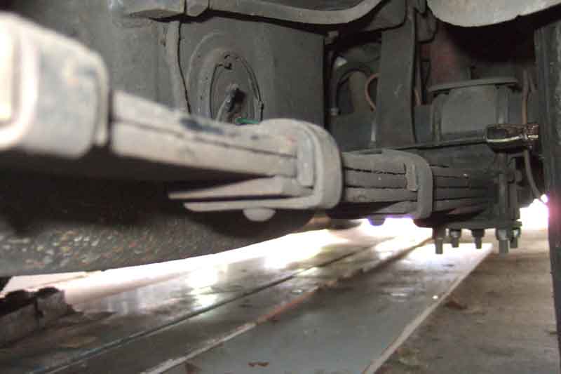
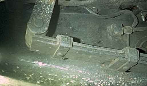
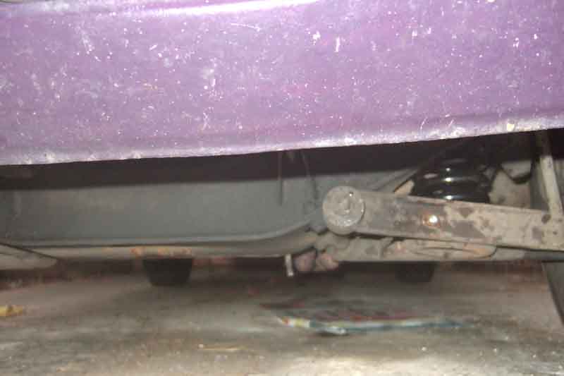
and may even be fully extended instead of mid-way between the extremes of its travel which is obviously very wrong. With the vehicle on its wheels, even with nothing in the boot/trunk, the rebound strap should be curved round in an arc, the lever-arm damper arms approximately horizontal, the springs nearly flat, and the shackles around vertical or pointing slightly rearwards, as shown in the pictures on the left of this paragraph (click to enlarge). The rebound straps must not be straight and under tension.
There have always been intermittent complaints from North America that new springs sourced locally raise the rear way too much
and sometimes are too stiff or arched to get the rebound straps or even the shackles installed without some serious extra weight in the boot/trunk. If you have to do that then at the very least the rear will be higher than it should
and may even be fully extended instead of mid-way between the extremes of its travel which is obviously very wrong. With the vehicle on its wheels, even with nothing in the boot/trunk, the rebound strap should be curved round in an arc, the lever-arm damper arms approximately horizontal, the springs nearly flat, and the shackles around vertical or pointing slightly rearwards, as shown in the pictures on the left of this paragraph (click to enlarge). The rebound straps must not be straight and under tension.
Currently there seems to be a real spate of problems (but see this), and people in the UK are beginning to complain of the same thing. You should be able to fit the rebound straps by jacking each spring up under the body - without any extra weight in the boot - before the body starts lifting off its supports. On UK-sourced springs I have done this without difficulty, even putting the harder rubber-bumper springs on a chrome-bumper car. Similarly people have asked how to get the shackles pointing to the rear instead of the front. Again it is a matter of spring hardness - the correct springs should be almost flat with just the weight of the unladen body, and as they take the weight of the body and start to flatten they will move backwards. If the weight of the car is on its wheels, even unladen, and they aren't pointing slightly backwards, the springs you have are simply too hard or over-arched for your car. However it occurs to me that all the work I have done has been on a chrome-bumper car. With the lower shackle mounting position relative to the chassis rails of rubber-bumper cars it is possible that these can lock in the fully forward position unless levered downwards while jacking slightly higher. However once the rebound straps are fitted this shouldn't occur again. Updated August 2007 and July 2010: Since writing this I've had to replace the rear springs on the V8 and a pal's RB GT. Having now bought three sets of springs from three different suppliers and fitted them to three different cars I have never had any problems using simply the weight of the body to compress the springs enough to attach shackles, damper drop-links and rebound rubbers, and this includes fitting harder RB roadster springs to a CB roadster. Nor have I had any problems with the shackle 'locking up' in a forward position on either CB or RB car. See Rear Spring Replacement.
My problem has been the opposite - ride-height too low and grounding over 'sleeping policemen' and rough ground particularly when laden (we use the car frequently for holidays with a comprehensive tool kit and trolley-jack as well as luggage). I had tried and removed rubber-bumper roadster springs as part of another exercise which raised the ride height just fine, but being harder they gave a very unpleasant choppy rise over some surfaces. In July 2003 I modified some shackles by 'cutting and shutting' to give about an inch extra height at the rear, as described below in 'Extended Shackles'.
Converting RB to CB Added January 2008 A number of factors to consider here:
Spring Specs Updated October 2008
| Car | Free Height | Spring Dia | Free Coils | Loaded Height | Load Weight | Rate lb/in | OE Part No. |
| Pre-72 Roadster | 9.9 | 3.238 | 7.5 | 7 | 1030 | 348 | AHH 6451 |
| Pre-72 GT | 9.1 | 3.28 | 7.2 | 6.6 | 1193 | 480 | AHH 5789 |
| 72 Roadster | 10.2 | n/a | 7.5 | 7.24 | 1030 | 348 | n/a |
| 72-on CB GT | 9.32 | n/a | 7.2 | 6.84 | 1193 | 480 | BHH 1077 |
| 73-on Roadster | 10.2 | n/a | 9 | 7.44 | 1030 | 373 | BHH 1225 |
| RB GT | 10.2 | n/a | 9 | 7.44 | 1030 | 373 | BHH 1225 |
| V8 (all) | 9.32 | n/a | 7.2 | 6.84 | 1193 | 480 | BHH 1077 |
| Competition lowered | 8.63 | n/a | 6 | 6.14 | 1193 | 480 | C-AHT 21 |
Notes:
- Information from Clausager, Factory WorkShop Manual, Factory Parts Catalogue, Special Tuning Manual, and Haynes.
- 'Loaded Height' is at the specified 'Load Weight' i.e. partially compressed. The difference between the free height and loaded height is the deflection, or the working load divided by the rate.
- The 73-on i.e. CB Roadster and the RB GT both had the same front springs which doesn't seem to make sense given that the RB GT is more than 100lb heavier than the CB roadster. Ian Caldwell found that the earlier AHH6451 gave a much better appearance, ride and handling on his 73 roadster.
- Clausager refers to a change in August 1972 just before the start of 1973 model year of a 1/2" increase to all models to prevent excessive settling on export models when lashed down on ships decks for long periods,
however the workshop manual shows a change of about 1/4" at that time.
- Clausager makes reference to what he calls a 'Part number change only' in November 1972. However the Workshop Manual has three sets of specs for the CB roadster - I have assumed (maybe wrongly) that the third set is in fact the November 72 set that Clausager mentions. I have called these '1973 Roadster'. Dave Wood states he received a recall notice for his 72B later that year for a spring change to raise the height by 1/4" to meet minimum headlight heights which would seem to concur with the workshop manual. The Parts manual only has two part numbers covering the change early in 72, not the change in November 72.
Spring quality in terms of what height you end up with has been problematic for years - sometimes higher than expected sometimes lower. If they are higher then about all you can do is opt for a softer spring from the list and hope, I wouldn't fancy cutting some off as some have apparently done. Finding them too low has happened when people have selected a 'lowered' or competition spring, and in that case you can put shims in the spring pan. Moss sell nylon spacers, these are 3/16" (5mm) thick, and say you can use two maximum, the outside of the spring pan is pretty deep but the inner raised section is less. The effect is about double at the hub so two will raise the front by about 3/4".
| Car | Leaves | Interleaving | Width | Gauge | Load (flat) | Rate lb/in | Deflection in | OE Part No.
| CB Roadster | to May 63 5 + bottom plate | None | 1 3/4" | 0.2187in | 400lb | 99 | 4.04 | AHH 6453 | (GSV 1006) CB Roadster | May 63 on 5 + bottom plate | 1/2 2/3 3/4 | 1 3/4" | 3@0.2187in, | 3@0.1875in 450lb | 93 | 4.97 | AHH 7080 | (GSV 1006) CB GT | 6 + bottom plate | 1/2 2/3 | 1 3/4" | 3@0.2187in, | 3@0.1875in 510lb-540lb | 99 | 3.2 | AHC 31
| RB Roadster | to Sep 75 6 + bottom plate | 1/2 2/3 | 1 3/4" | 3@0.2187in, | 3@0.1875in 510lb-540lb | 99 | 3.2 | AHC 31
| RB GT | 6 + bottom plate | 1/2 2/3 | 1 3/4" | 3@0.2187in, | 3@0.1875in 510lb | n/a | n/a | BHH 1767
| RB Roadster | Sep 75 on 5 + bottom plate | n/a | n/a | n/a | n/a | n/a | n/a | BHH 1779
| RB GT LHD | Sep 76 on See note 4 6 + bottom plate | 1/2, 2/3 | n/a | 3@0.2187", | 3@0.1875" 450 | n/a | n/a | n/a
| CB V8 | 6 + bottom plate | 1/2, 2/3, 3/4, 4/5 | 1 3/4" | 3@0.2187", | 3@0.1875" 550lb | n/a | n/a | BHH 1133
| RB V8 | 6 + bottom plate | 1/2, 2/3, 3/4, 4/5 | 1 3/4" | 3@0.2187", | 3@0.1875" 550lb | n/a | n/a | BHH 1771
| Competition | n/a | n/a | n/a | n/a | 375 | 100 | 3.75 | C-AHH 8343
| Competition | n/a | n/a | n/a | n/a | 542 | 124 | 4.37 | AHH 7346
| Competition | (lowered AHH 7346) n/a | n/a | n/a | n/a | 542 | 124 | 3.37 | C-AHT 20
| |
Notes:
1. Information from Clausager, Factory Workshop Manuals, Factory Parts Catalogue, Special Tuning Manual, and Haynes.
2. Although the roadster originally is described as having five leaves and a bottom plate ('six leaves' elsewhere) and the GT is described as having six leaves and a bottom plate ('seven leaves' elsewhere) both the 63-on CB roadster and various GT springs are described as having 3 leaves of each thickness. This seems contradictory, and the roadster did get shorter U-bolts when it reverted to the previous number of leaves in September 1975.
3. These springs are listed - without prices - by GB Springs as 'Heritage Car Springs', with some variations from the original part numbers. Some of these seem to be where the spec was changed for a particular model, only the later spec is now supplied, for example only one CB roadster spring is listed whereas until May 1963 a different spring was used. Also they don't list a CB GT spring but it was the same one used for early RB roadsters i.e. AHC 31.
4. With 11/16" rear ARB.
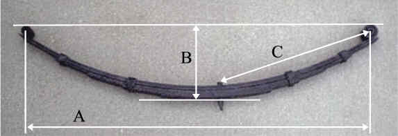
Unloaded Rear Spring Dimensions
| A | eye centre to eye centre | 41 1/4" |
|
| B | inverted height from floor to top of top spring | 8 5/8" | |
| C | front eye centre to pin top centre | 19 1/8" |
See also the picture on the right of the table.
Remember these are relatively new rubber-bumper roadster springs, but all others should be close. If your dimension A is significantly less and B is significantly more then over-arching is the problem. If the dimensions are close but you still cannot compress them enough during installation, or the resultant ride-height is much too high, then the leaves are much too hard. In either case get your money back and source them from a reputable supplier in the UK.
April 2021:
 See also Tony Davison's measurements of old and new CB springs, and his account of replacing them.
Update January 2013: By now it's probably best to leave off the 'in the UK' as people here are getting duff springs as well. But Mark Bates in the US had the 'submissive monkey' stance, the rebound rubbers were pulled taut and snapped while parked. He removed them and found that dimension B - the arch - was fully an inch and a half more than mine. He purchased another set from The B Hive in America and they do have very similar unloaded dimensions to mine.
See also Front and Rear Suspension Considerations from Doug Jackson's British Automotive site.
August 2025: Ian Caldwell has written to me about problems with replacement front springs. He had one break on his 72 built, 73 model roadster in 2014 and replaced both with BHH1225PR from Moss UK on the understanding they were the correct ones for the car. However that put the front ride height (hub centre to lower edge of trim strip) at 386mm i.e. more than an inch too high making the front significantly higher than the rear and it didn't improve over time. According to the Leyland Parts Catalogue BHH1225 was fitted to chassis number 293446 (roadster) 296192 (GT) in August 72 for the remainder of CB production (Clausager: "New front springs, to increase the ride height at the front of the car by 0.5" in order to overcome the problem of 'settling' due to export cars being lashed down on board ships") so should have been correct for Ian's car. But BHH1225 is also specified for RB GTs (and roadsters) to the end of the 76 model year so how can the same spring be correct for both CB roadster and RB GTs which weigh over 100lb more? BHH1225 are rated at 373 lb/in., they replaced the earlier CB roadster AHH6451 springs which are 348 lb/in. and I suggested to Ian he could try those. Several suppliers list them, some quoting a rating of 350 lb/in i.e. basically the original figure. He went ahead and is happy to report that the car now sits right with a front height of 355mm i.e. a reduction of 31mm. Ian also reports that on B roads with lots of undulations the ride and handling are also improved. See also this on A-arm bushings.
Replacement: The first thing to say is that spring compressors are not required. Support the front of the car safely e.g. with axle stands under the chassis rails and/or front crossmember. Place a jack under the spring-pan and raise the axle until the upper damper arms are just clear of both the rebound rubbers.
Most seem to agree thus far, but opinions differ as to whether the four bolts that secure the spring-pan to the lower A-arms should be removed next and just the spring-pan lowered to free the spring, or whether the lower trunnion bolt should be removed disconnecting the A-arms from the swivel axle, and the A-arms and spring pan complete lowered to free the spring.
Having tried both ways I would only ever recommend the latter method, for the following reasons:
Secondly, it is my experience that the tapered ARB drop-link pin (all bar 74 to 76 RB roadsters) seizes in the spring-pan, and the two have to be removed together for them to be parted on the bench. If this happens you have no option but to use my preferred method as follows:
Removing the lower fulcrum pivot bolt (through the swivel axle trunnion and outer end of the A-arms) is a single operation and allows you to lower the spring pan on the jack while it is still held securely, until all spring tension is released. With the jack out of the way you push the pan down a bit more with one hand and simply lift the spring out with the other (but see below). That done, you can tackle the spring-pan to A-arm bolts in complete safety.
This method also allows you to inspect the thrust-washers on the pivot bolt, and reverse or replace them if grooved which can silence clonks when applying the brakes.
Another more recent option has been to remove just two of the spring-pan bolts, and slacken the other two, then allow the spring pan to pivot down on the A-arms. But the A-arms are not parallel so the pan is going to bind between the arms unless the slackened bolts are very slack. This will almost certainly have to be the inner bolts given that the ARB drop-link pin seizes in the spring-pan. Also if removing the spring is anything to do with working on the A-arms, replacing the inner bushes, or any of the pivot pin components, the pivot pin will have to be removed anyway so you might as well do it up front. With the rear two bolts through the spring-pan and A-arm removed, and where fitted the drop-link detached from the ARB, both A-arms can be removed, the front one complete with spring-pan and drop-link.
I did use this method to reassemble with new CB roadster springs which have a long free height and I couldn't push the A-arms down far enough to insert the spring. But then I had to move the jack from the middle of the spring-pan to the very outer edge before I could compress the new spring enough to get the fulcrum bolt fitted. Leaving the A-arm to spring-pan bolts slack also helps with refitting the pivot bolt through the arms and the trunnion, if the holes are offset you can't get the bolt through the second A-arm hole. If none of the spring-pan bolts have been loosened the ends of the A-arms should still be in line.
Some have said that just letting the suspension hang down on the rebound rubbers takes enough tension out of the spring to be able to remove the pivot bolt or the spring-pan bolts safely, which could be the case with the shorter and harder front springs, but until you have done it once you won't know, and you don't want to find out the painful way that it isn't the case!
In the time-honoured phrase - "reassembly is the reverse of removal" - that is, push down the A-arms complete with spring-pan, insert spring, jack spring-pan and pivot swivel-axle until the lower bolt can be inserted. The only thing to watch is that the grease seal, thrust washer and seal support are all present and correct on reassembly.
Another tip when buying new springs of any type is to insist on a pair with the same free height! The pair my supplier put on the counter for Vee differed by nearly 1/4". He got a matched pair without quibble, but said "it won't make any difference". At first I thought he meant that the free height made no difference to the loaded height which is obviously wrong, but once fitted although the loaded height had been the same with the old springs with the new, even after a shakedown run, there was a 1/2" difference. So maybe he meant "it doesn't matter what the free height is, the loaded heights will probably be different anyway!". Also the free heights were quite a bit higher than spec, so if you are able go for the shortest.
Update September 2007 Another tip is that when sliding the A-arms down off the trunnion, as soon as the hole in the trunnion is cleared refit the bolt and nut and this will stop the grease seals etc. falling off and the bolt/nut getting dirty/lost. But I digress. Many moons ago for various reasons I fitted CB GT front springs to the roadster as they are stiffer, but with a lower free height, which gives much the same ride height. At the time they gave much the same ride height with less roll and dive under braking, but since then they have settled and for some time I haven't been able to get the hydraulic jack under the rear edge of the cross-member, and the A-arms and track-rods were both angled upwards (outer ends relative to inner) which didn't seem to me to be correct. So I decided to replace them with new originals, and in doing so found that I needed to employ a combination of the two methods above. The CB GT springs have a free height of 9.32" (and the used ones were a little less than this anyway) and pushing down on the A-arms/spring pan with the lower fulcrum pin removed was all I needed to do to get the old spring out. However the correct springs have a free height of 10.2" (and in fact the new ones were a little taller than that) and I could not push the arms down far enough to get the new spring located in the groove in the spring pan. So I removed the inner spring pan bolts altogether, and with the outer bolts slackened (actually only the bolt as I couldn't get at the anti-roll bar drop-link nut easily) the pan pivoted downwards with a bit of pressure and in went the spring. I then jacked up under the inner edge of the pan, and with a bit more levering got the holes aligned and the bolts back in. This is still a much safer method than complete removal of the four spring pan bolts as the pan and hence the spring is still securely retained by the outer two bolts (or bolt and anti-roll bar drop-link pin). So far so good, but when I jacked up under the spring pan I found I couldn't compress the new springs enough to get the holes in the fulcrum and A-arms aligned, I had to jack under the far outer edge of the pan to be able to do it. Not only that, but when on the ground a quick measurement showed that the front ride height had leapt up from 14" to 16" and looked ridiculous!
 Not being a believer in springs 'settling' soon after installation, nevertheless a tour round some of the speed-hump ridden streets of Solihull and some bumpy country lanes for an hour settled them to 15.375" at the front both sides, with 14.125" at the rear also both sides. Better, but still a little high at the front, but it will probably settle more over time. I think the initial settling is due to the front springs only sitting in the spring-pan and cross-member, and so not fully seated until they have been worked up and down a bit. In contrast the rear springs are positively located by bolts and I'd expect very little initial settling. The A-arms and track rods are now angled slightly downwards (click thumbnail), and I now have 6.625" clearance under the front cross-member as opposed to about 5.5" previously.
Update October 2007
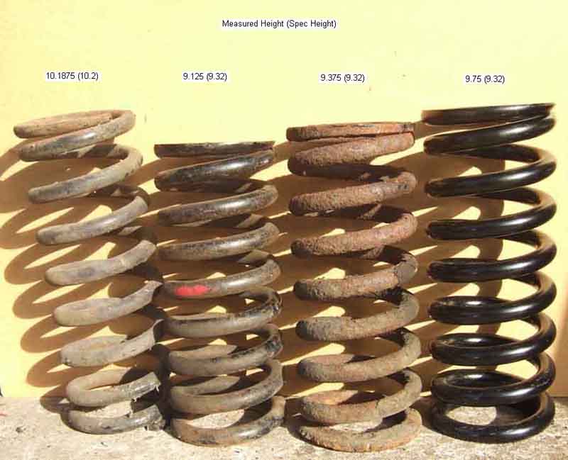 Replaced Vee's front springs today. Being shorter it was much easier than Bee's, I only had to remove the anti-roll bar and lower fulcrum bolts, and slacken the bolts between the spring pan and the rear A-arm. Pushing the pan and A-arms down the old spring came out easy enough, although the axle assembly kept pivoting inwards getting in the way, and I didn't have enough hands to hold that out, push down the spring pan and lift out/replace the spring, so I propped the axle assembly up out of the way with a piece of wood between the hub and the ground. Didn't take much more than an hour each side. Before starting the ride height between hub centre and bottom of the trim strip was 14.5" on the right and 14.625 on the left. Immediately after replacement the right was 16.25" and the left 16.5", and after a couple of miles over the speed bumps came down to 15" and 15.5" More disparity there than originally, and the springs were the same free height, so we'll see how it goes. Clearance under the Y-pipe on the exhaust is now 4.45", up from 3.5" before, which was way below the spec ground clearance of 4.25". This thumbnail shows (from left to right) the original roadster springs (with a nice curve in them!) taken out some years ago, the newly removed CB GT springs, and new V8 springs waiting to go into Vee.
Update October 2009
Measured Bee's ride height as 14.75" right front, 14.625" left front, and 14.25" for both rears. Vee's are 14.5" right front, 14.625" left front, 15.375" right rear, and 15.6875" left rear.
Update May 2022
Bee 14.5" right front, 14.4" left front, 13.875" right rear, 14.25" left rear. Vee 14" right front, 14.5" left front, 15.5" both rears.
All measurements eye-balling the centres of the hubs so not accurate to the thou. Significant change in the first two years then very little in the dozen years since, most of which has been spent surrounded by 'traffic calming' measures but without a deterioration in ride height.
Lubrication
Mounting
Replacement
Extended shackles
It is purely the leaf springs that locate the rear axle in the car, nothing else. Just in case you wondered how much it moves around under acceleration and cornering forces, have a look at this Healey video which has much the same leaf spring and lever arm damper arrangement: https://www.youtube.com/watch?v=tN-4LLAKlpw. Note that the movement is nothing to do with the lever-arm dampers, telescopics would make little if any difference. You would need a multi-link system to positively locate it against rotation about the half-shafts and sideways movement.
I actually painted it on semi-congealed rather than as a liquid suitable for spraying, then used a hot air gun to melt it whereupon most of it was absorbed into the gaps between leaves and interleaving and little dripped off. At first it didn't seem to have made much difference, but then over a bit of driving it seems to have 'worked in' and they have definitely become much quieter and now I can't say that I notice them at all and neither has the Navigator commented recently. It would have been much easier to apply with the springs removed from the car and laying on their sides, but a much bigger job overall of course.
In response to a question on a Bulletin Board I mentioned this but another contributor said he didn't like Waxoyl because it dried out. In my experience whilst it does 'dry' in that the white spirit that makes it liquid evaporates it leaves behind the waxy stuff which if you rub it between your finger tips is still slippery i.e. does still lubricate, and as I say is much less likely to get washed out than oil or even grease. And being drier it will pick up less dirt and grit.
Update August 2007: Having broken a rear spring on this year's Snowdon Run before I replaced them I laid the new springs on their sides, painted on some dollops of Waxoyl, then used a heat gun to melt it into the crevices between springs and interleaving. When they were 'dry' I could pick them up by the eyes and it was a cleaner job than I was expecting to fit them while coated. Incidentally, this is the third set of springs I have bought from three separate suppliers and fitted to two different cars - one chrome one rubber, including stiffer rubber bumper roadster springs to the chrome bumper roadster, and I have never had any trouble getting the shackles, damper drop-links or rebound rubbers attached, or in getting the shackles to point downwards. The weight of the body was more than enough to compress the springs before the body lifted off the axle stands in all cases.
Rear spring mounting June 2016
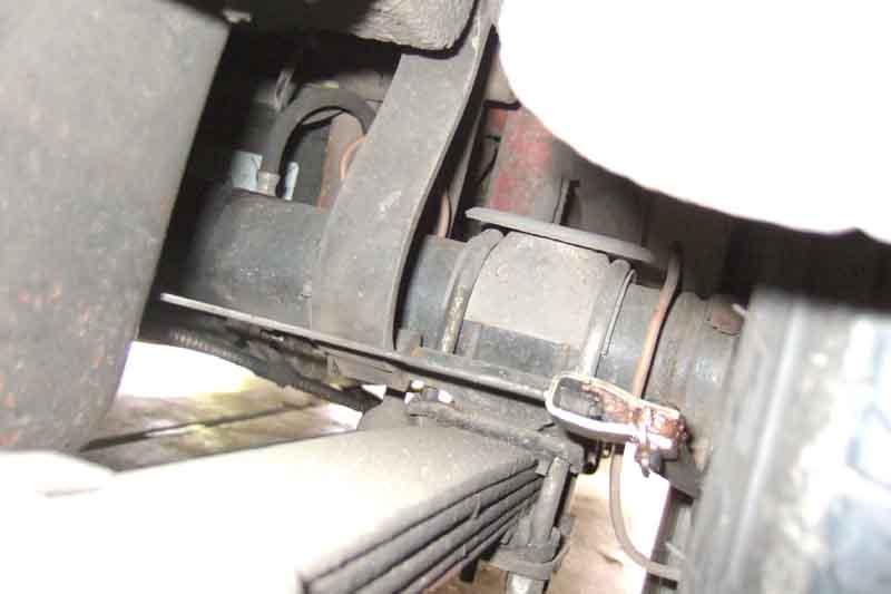
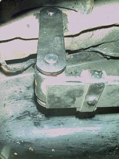
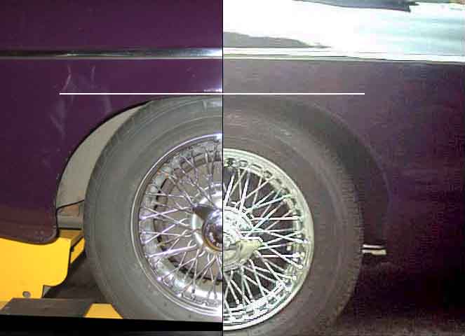
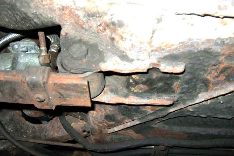 It's well known that rubber bumper cars higher ride height is obtained by a modified crossmember at the front and lowered spring mounting points at the rear, and this applies to both 4-cylinder cars and V8s. Also that the V8 chrome bumper was the first to use the modified crossmember as it needed more ground clearance for the exhaust than the 4-cylinder. But what about the rear springs on chrome bumper V8s? Over the years I've seen arguments as to whether the rear mounting points on these cars were lowered or not, and I've been intrigued as to the answer. At a recent MG run I had the opportunity to find out as there were not one but two chrome bumper V8s. When parked up at the finish I happened to see the cars, no owners in attendance to ask, so I took some surreptitious pictures.
The results were quite interesting: Both 4-cylinder and V8 rubber bumper cars have lowered front and rear mounting points consisting of a deeper front bracket and the holes for the rear shackle pins being below the centre-line of the chassis rail, but the chrome bumper V8 only has deeper front brackets, the rear points are through the chassis rail just like the 4-cylinder car. Even so the front brackets are different between chrome and rubber bumper V8 - the rubber bumper part looks deeper than the chrome bumper, and has a reinforcing piece, and this partial lowering at the rear seems to be confirmed by the CB V8 drop-link being 9.75" long whereas the CB 4-cylinder is 8.5" and all RB cars are 10.5" . Whilst British Motor Heritage lists rear spring front hangers, it only differentiates between chrome bumper and rubber bumper, V8 is not mentioned, ditto Brown & Gammons and Moss Europe which quote the BMH part numbers.
Rear spring replacement November 2010:
October 2024: September's issue of the MGOC Blog has an article on rear springs including replacement items. For rear springs they say "MGOC Spares offers a full range of leaf springs from Q Parts manufactured to exacting standards, offering unbeatable quality with features not found elsewhere with the peace of mind that our springs have undergone rigorous testing and have been developed for real world use. They are not marketed as original but supplied under a ‘Q’ suffix, meaning uprated owing that Q Parts Springs springs are rated a little higher than standard to provide a much longer service life than so-called original springs, which we find do not last." These have RSK part numbers.
June 2016: I've just become aware of a news item posted in 2015 on the West Cheshire MG Club website (scroll to the bottom) saying that BMH guarantees correctly specced springs made by GB Springs. However I can find no reference to them on the BMH website. But GB Springs on their website do list what looks like the full range for the MGB at least, plus for other models and marques.
February 2023: At last as a result of conversations with Noel Wade I've found this page which includes the following:
...
Concluded John Yea: “From hereon we will use the British Motor Heritage label on all our springs. This is the customer assurance that the product is as close to the original manufacturer’s specification as possible, and that the quality of the spring has been validated and therefore justifiably carries the original part number. Without this sign of authenticity, it is really a case of buyer beware.”
Also this BMH page with links to the full BMH brochure, listing products from GB Springs on page 150 (of the printed brochure, page 53 of the PDF) which include those on the GB Springs page plus AHT20Z uprated 2" lowered.
March 2023: Noel has contacted me again to say that several suppliers now have the GB Springs with the Heritage sticker, including Moss where he has purchased his. I'm hoping to get an update following installation. However at the time of writing looking at the specifications of the six springs Moss list three say 'after-market' and three don't, so you would need to check with Moss.
April 2023: Noel has now got his car back, it sits level and at the correct height and he is very pleased.
August 2007:
 Spot the difference. Following the breakage of a rear spring on the V8 on the 2007 Snowdon Run I ordered replacements from the MGOC and approached fitting them with some trepidation. Would I have the same over-arched/too hard springs that so many seem to have? Would I find the bolt seized in the front eye bush that Americans frequently complain of? In the event I had neither. The front nuts came undone easily with nothing more than a spanner, and when the shackles and U-bolts had been undone and the rear of the spring lowered to the floor the bolts just tapped/twisted out. With the new springs fitted and the weight on the car there is a decent amount of slack in the rebound strap, about 3 1/2" between the top of the bump-stop pedestal and the bottom of the bump rubber, and about 15 7/8" measured between the centre of the wheel hub and the bottom of the trim strip.
On fitting the new springs one point that did differ on the rubber bumper V8 compared to the CB roadster (both CB roadster and RB roadster springs on this car) is that on the V8 I only had to lift the springs up by hand and I could insert the shackles. On the roadster I had to jack under the spring to slide the rear eye back along the chassis rail until I could get the shackle inserted, probably because the harder RB V8 springs had less free arch than the CB roadster. One problem I had with the V8 that I hadn't had with the roadster with either new red poly bushes at one time and new rubber another, is that the latest bushes have a significantly thicker flange than before, which meant that even without the lock-washers I couldn't get the nuts started. I had to squeeze the sides of the shackle together with a small sash cramp to compress the bushes before I could get the washers on and the nuts started. Other than that everything was straightforward, the only complication on the V8 being the Hopkinson anti-roll bar. To get the bracket of this located on the U-bolts I had to jack under the spring until the bracket was just below the end of the U-bolts, then slowly lower it whilst locating the bracket holes over the threaded ends, until enough thread was sticking through to get the nuts started. Both the front eye bolts and the shackle nuts are done up until they suddenly come tight as the front hanger butts up against the bush sleeve, and the shackle pins have shoulders which the closing plate clamps down onto. How tight to do the U-bolt nuts is always an awkward question - I've never seen a torque figure given, so how tight do you go? Having done this job several times now it seems to me that as you start to compress the flat rubber bushes either side of the spring the nuts get stiffer quite gradually, then they seem to get quite a bit stiffer quite quickly. This is about the point I stop, but they need checking again after a short shakedown drive, and again several hundred miles later (checking the front eye bolt and the shackle nuts as well this time). During my shakedown drive I noticed some creaking coming from the right-hand side, on my return I could tighten this side quite a bit more (possibly as I did that side a couple of days prior to the left-hand side) and on a second run the creaking had disappeared. One thing that did not change was the rear ride-height.
One thing I did which I usually do when re-fitting MGB components, to ensure easy removal in the future, is to coat the front bolt and bush and the rear shackle pins and bushes and the rear chassis holes with Waxoyl. Before fitting I had also laid the springs down on one side, painted a decent layer of Waxoyl on, then ran my heat-gun up and down to completely melt it into the joints between springs and interleaving. When that had solidified I turned them over and treated the other side. Not even that messy when picking them up to fit to the car, and that is what latex gloves are for.
So I have now bought three different types of spring, from three different suppliers, over a period of years, and fitted them to two different cars, and never had the 'too-hard/arched' problem that so many complain about. Am I just lucky? Or is everyone that gets this problem buying from dodgy suppliers? Or are they simply not installing them correctly? I wish I knew.
July 2010: A pal's MGB fails its MOT with a broken rear spring.
 Unlike the V8 it wasn't obvious as the wheel was still central in the wheel arch, as this car has the factory rear anti-roll bar which controls the fore and aft position of the axle. I suppose the ride height might have been a little lower that side but it wasn't obvious. Keith brought it round, but when the door bell went I hadn't heard the car, apparently it had conked out round the corner! This time (on the last visit it conked out two streets away, so an improvement) a fuel leak had developed and emptied the tank. A short push to a convenient slope allowed the car to roll round the corner and onto the drive, so that was going to be the first job. In the event the rubber hose between the pump and the metal pipe leading to the carbs had split, so an easy fix, and I was able to manoeuvre the car into the best place for the spring change.
For security I drove the front of the car up onto ramps, with the front of the car pointing down the slight slope on my drive. The rear was supported on axle stands just in front of the front eye, with pieces of wood inserted into the flanges of the bracket between the floor reinforcement section an the axle stand. If one end is on its wheels and you are pulling an pushing at things it's very easy to tip stands over, particularly if its the front on the ground and the rear in the air, even with chocks.
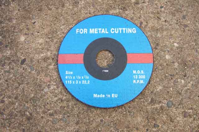
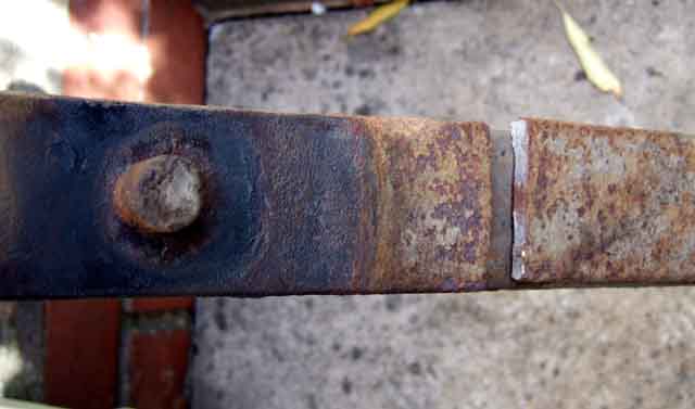
This time not so lucky as both front eye bolts are seized in the spacer tubes. I can turn the bolt with a spanner, but as I release the pressure I can feel them springing back a bit, so the spacer is turning inside the rubber bush. Pondered cutting through with a jig-saw, but they can only cope with a few mm of metal, so opt for a cutting disc for the (4 1/4") angle-grinder. Only had grinding discs before, which are thicker and have an off-set flange. Discovered that with the thinner, flat cutting disc the locking ring has to be turned over so the flat side contacts the disc, as otherwise it isn't gripped.
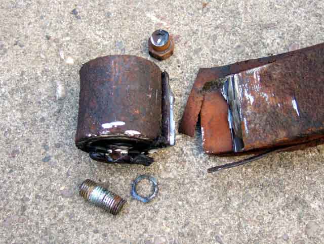
Decide to cut the spring off the eye as close to the eye as I can, to give me as much space as possible to cut up the sides of the eye and through the bolt and spacer tube. I was gobsmacked at how quickly it made the first cut, probably less than a minute, and with that out the way the other two cuts probably less than 2 minutes each. Angle the grinder for the first cut so the sparks fly away from the car and not under it, and downwards for the other two cuts. This meant that with one of the cuts each side it didn't go through all the way in one go, so just turn the eye 180 degrees and cut through the rest. The eye just dropped out of the bracket, and a bit of wiggling got the thin ring that was the end of the spacer tube off the remains of the bolt. Less than five minutes, and no collateral damage to the bracket or anything else, it took me longer to get the spring and bottom plate off the U-bolts!
One bump-stop pedestal had completely rotted away, and the other was hanging on by a thread, so replacements needed for those as well as the front eye bolts. Reassembled everything with Waxoyl, turning to a clear liquid on what was a very warm day. As on the V8 with the front eyes mounted the rear shackles lined up with the chassis rail holes without compressing the spring, neither did the shackles lock under the chassis rail when I jacked up under the spring to fit the U-bolts and bottom plate. Again the U-bolts and plates were the biggest fiddle, getting them lined up, and getting the 'bump' in the top plate lined up with the hole in the bottom of the axle spring-pad. The factory anti-roll bar makes this slightly more difficult as you can't move the axle fore and aft directly, you have to rotate the whole axle to move the spring mounting pad into position over the spring. The second side is even worse as with the first side fitted you can't even do that, and a firm push from a foot on the brake drum was needed. One thing I noticed is that the new front bolts are only just long enough, and that is with the old nuts and lock-washers. Nylocs were supplied with the bolts but to be honest I don't think they were long enough to get the requisite minimum three threads clear, as it was the end of the bolt was just shy of the end of the nut. Other than that (well, there are only the shackles left!) it all went back together inside the hour, and that includes wheels on and tools etc., put back in the garage.
Herb Adler tackles the same problem.
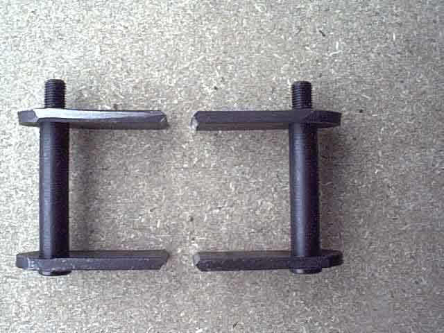
In July 2003 I decided I had to do something about it. I did have rubber bumper roadster springs on for a while (part of another exercise) and whilst these gave me the extra height they were also harder and gave a choppy and unpleasant ride over some surfaces and eventually the proper springs went back on. I considered re-arching these springs but felt that would be a bit hit and miss. The alternative was longer shackles. I was surprised to find that rubber bumper and chrome bumper cars used the same shackles. Seeing as how the front eye is only about an inch or so lower, but the car is 1 1/2" higher, the extra must come from extra spring hardness and/or arching and this does seem to be the case on my RB V8. I did find some adjustable shackles but they are very expensive, more than I was prepared to spend. A few enquiries elicited no other sources of longer shackles, other than paying an engineering shop to produce some, or modifying standard ones myself.
The very expensive adjustable shackles mentioned above have three pairs of holes for the bottom pin, which is just a long bolt going through both plates. The originals have the pins pressed into splined holes in the shackle plate and the pins have a double shoulder at the threaded end, the smaller of which fits into the hole in the closing plate. This keeps the threads away from the side of the hole so protecting them, but more importantly makes the tightened shackle a rigid parallelogram, aiding spring and hence axle location. Plain bolts will allow the rectangle of the closed shackle to be distorted into a rhomboid during cornering, which will give more lateral movement of the spring and hence the axle. Over time this will tend to make the holes in the plates oval and wear grooves in the bolts so weakening them. There is also the issue of tightening the shackles. Even when the original shackle is tightened to 30 lb.ft. the bushes are only lightly nipped and there is clearance for the spring eye to pivot on them. But without some form of spacer tube a plain bolt is going to tighten the shackles onto the bushes and spring eye, restricting movement, and probably damaging the bushes in a short time.
I decided to modify some myself. But rather than cut up and weld a piece into my existing ones I bought two pairs of the standard items and used those. This was for two reasons - I wanted a 'proper' set to go back to if I needed to, and I wanted only one weld in each rather than two. In the event it was an easy enough job and if I were doing it again I would extend the existing pair with two welds and a piece of flat bar and save myself £40.
The first job was to decide how long - the distance between the centres of the shackle pins - I wanted them to be. The standard items are 2.5", I wanted about an extra inch as measured between the hub centre and the bottom of the chrome strip, and given the various angles and lengths of parts I reckoned on about 1.25" longer at the shackle, i.e. 3.75" in total. I didn't want to guess and get it wrong but be a bit more scientific, so I made up two wooden blocks to go between the spring eyes and the chassis rails, shackles removed, then added and removed further wooden 'shims' until I got my 1" extra between hub and trim. This was a bit of a fiddle, jacking and lowering the spring and axle, but fortunately I got it right on the second go. I then measured the distance between the centres of the holes in the chassis rail and spring eye, and it turned out to be 3.75". Oh well, at least I knew it was going to be right.
At this point a word about removing the springs. I say 'removing' but I didn't actually remove them altogether, the front bolt was all that was left so the following process is good for complete removal too:
- Jack under the axle to raise the back of the car off the ground and securely support the body under the rear spring front mounting point reinforcing plates, high enough so that the wheels are off the ground when the jack is removed.
- Lower the axle so it is suspended on the rebound straps, or, if your straps are broken or suspect don't go any lower than good rebound straps would allow to avoid stressing the dampers or rear brake flex hose, and support the axle near the bottom of its travel on axle stands. Now would be a good time to replace bad rebound straps!
- Now jack under the spring itself, close to the U-bolts. Raise it a couple of inches or so but not so much as to start lifting the body off its supports.
- Remove the four U-bolt nuts, pull the damper mounting plate and spring locating plate down off the U-bolts and push them towards the front of the car so that they are under the front half of the spring. If you raised the spring and axle high enough above this is easily accomplished in the normal downward travel of the damper.
- Jack the spring down, it will clear the U-bolts, and keep going until all tension is released, pushing the damper mounting plate further forward if required.
- Remove the rear shackle. With no tension in the spring you should be able to wiggle it about to get it free once the closing plate is off. If the rubber bushes are damaged or perished change them.
- Removing the front mounting bolt now will allow complete removal of the spring, if required. Take care, they are surprisingly heavy! If the drivers side has sagged more than the passengers swapping over the springs will restore an element of balance when the car is occupied.
By putting wooden blocks between the spring rear eyes and chassis rails and varying the thickness of the blocks with shims, supporting the springs under the axle on jacks and lowering the car till the tyres just touch the ground, you can get a reasonably accurate measurement of the distance between the centre of the hub and the bottom of the trim strip as it will be in normal use. The distance between the centres of the holes on the spring and chassis rail then determines the required shackle length. With a pair of dial calipers I used the outside jaws to measure the distance between the closest part of the two holes, then used the inside jaws to measure the furthest part, halved the difference and added that to the lowest figure to get the centres.
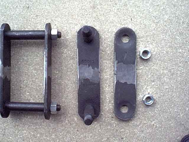
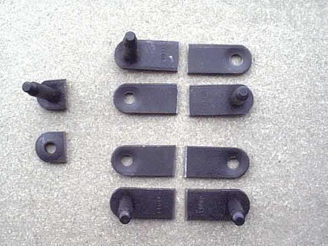 By cutting and shutting two pairs of shackles, as I was, you then have to determine where to make the cut. I felt it best to make each half the same length, which meant half of 3.75" i.e. 1.875" from the centre of one of the pins. Careful measuring, scribing and cutting produced the pieces as shown in the picture on the left (click to enlarge). As well as the pieces from four shackles which are going to be welded together to produce two, you can also see an example of the discarded parts of each shackle. 3/75" is just inside the flat part of the shackle plates, much more and you would be cutting across the dished part (which is no big deal but it would look a bit odd when welded together), and you only have about 0.25" available anyway before you reach the pin. Don't weld half of a closing plate to half of a pin plate as I have the top ones laid out! I didn't, but only noticed I had them laid out incorrectly when viewing the picture when I came to write this account.
 I wanted to grind the welds flat after fabrication, so to get maximum strength from the weld I ground both sides of each cut edge at an approximate 45% angle to make a 'V' groove each side when the pieces were put together, as shown in this picture. Not terribly clear, but you should be able to make them out.
Next came the job of welding them together. I decided to do the shackle plates before the closing plates as I considered the former easier to get aligned with reference to each other, then the closing plates can be aligned with reference to the welded shackle plate. The shackle plates need to be aligned such that the pins are parallel in two dimensions - one so that the centres of the pins are the same distance apart for the whole of their length, and the other so that the two pins are at the same angle when viewed one behind the other. Finally the two halves of the shackle plate should be as level and flat as the previous two alignment criteria allow. I opted for holding them lightly in a vice across their width, tapping first one then the other until all three criteria were met, then tightening the vice and making sure they were still correctly aligned. Because I was welding two halves of different shackles together they were of slightly different widths which meant that when one was tight in the vice the other was still loose, so I used some thick card as 'soft jaws' which deformed and gripped each half with relatively equal force. I MIG welded one side filling the 'V', checked the alignment again, then turned them over and welded the other side filling the other 'V'.
 The closing plates are less critical, only having to get them flat and level, and using the completed shackle plates to ensure that the holes are at the correct centres. The welded and ground parts can be seen here.
All that remains is to fit them. With the U-bolts undone and the spring tension released you should be able to insert the shackles and bushes into the spring eye and chassis rail quite easily. Because they are longer than the originals and because the spring may be resting on the previously removed damper locating plate in its forward position, you may have to pull the rear end of the spring down a little against its tension in order to get the shackle in. You may also need a little Waxoyl or washing-up liquid on the bushes to act as a lubricant to aid insertion. Don't use oil or grease as it will rot rubber. Fit the closing plate, spring-washers and nuts. When tightening the nuts they may tighten up before the shoulder on the pin has located itself into the hole in the shackle plate, then come looser as they locate properly, before finally tightening up to 30 lb.ft.
 Jack the spring up under the axle, fit the spring locating plate and damper mounting plate onto the U-bolts, and fit and tighten the U-bolt nuts. The Workshop Manual shows double-nuts which can be locked together, but Nyloc nuts seem to be fairly common these days. Some say Nyloc nuts should only be used once, but I have seen a reference in a manual that says as long as you can't turn them with your fingers they are fine to reuse. If in doubt replace them. All that remains is to jack under the axle so you can remove the body supports, lower the wheels to the ground, and measure your new ride height after a short drive to settle things. After a longer drive recheck the tightness of the shackle and U-bolt nuts. The fitted shackles can be seen here, pointing slightly to the rear, and not far off right-angles to the spring which is nearly flat.
A comparison of 'today' (February 2017) with when first modified, after some 14 years and 25k miles:
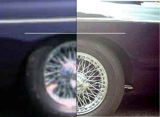
Note that extending the shackles will apply more leverage to the chassis rail bushes so you can expect a little more lateral axle movement when cornering. Bee's 175 tyres do rub both sides occasionally, but that is a factor of wheel offset with her after-market wire wheels more than anything else.