


Contents
Index
So you think you want an MGB or V8?
Body
Brakes
Clutch
Cooling
Electrics
Engine
Fuel
Gearbox
Heater
Ignition
Propshaft
Rear axle
Steering and Suspension
Wheels and Tyres
Miscellaneous
Downloadable PDFs
The sectioned MGB at the British Motor Museum, Gaydon
Steering and Suspension
|

Coming to an MOT test station near you - shaker plates to tear your steering and suspension to pieces.
If ever there was a good reason not to put your classic through an MOT ...
Springs, dampers or shocks/shockers/shock-absorbers? MGBs came out of the factory with springs and dampers. Whilst the term 'shock-absorbers' can be used for coil-over systems where you have a spring and damper in a sub-assembly, it is incorrect to use that term for the MGB damper. It's the spring that absorbs the shock of a bump or pot-hole, so if anything it should be interchangeable with that term and not damper. But once a spring has absorbed a shock it has to give it up again, and the damper is needed to 'damp' that reaction, without it the car will go bounding down the road like a kangaroo.
V8s are a one-piece assembly where the rubber bush is bonded to a steel spacer tube to give more positive handling. With these it is important not to tighten the pivot pin castellated nuts until the weight of the car is on its suspension. This is because the outer part of the rubber is a tight fit into the A-arm, the steel tube acts as a spacer and is clamped tight onto the wishbone pivot by the nut and large washers, so the action of the suspension tends to twist the rubber rather than slide it over the spacer. If the castellated nuts are fully tightened with the suspension hanging down then when the car is on its wheels there is already a lot of twist imparted to the rubber, and when the suspension is compressed over a bump the rubber gets twisted even more and can tear.
September 2025: What to replace suspension bushes with in these days of poor quality rubber? Ian Caldwell had a front spring break on his 73 roadster and then had excessive ride height despite fitting what were ostensibly the 'correct' springs, but there is an alternative which gave a great improvement. He replaced the inner A-arm bushes at the same time with standard rubber which collapsed in about 200 miles, then replaced those with Polybush 'comfort' which reputedly replicate the OE rubber and improved things further. Available for both front and rear, select the item then chose 'Comfort' under 'Select an option'. But note:
- Unlike standard V8 A-arm inner bushes Polybush for use here do not appear to have steel sleeves. The only one for the MGB showing a sleeve is the rear spring front eye as originally.
- There have been several complaints about polyurethane bushes squeaking in use even when the grease provided by some manufacturers has been used. Polybush actively discourages the use of grease saying it can cause squeaking as well as attracting grit which can accelerate wear.
- Brown & Gammons in their 'POLYBUSH' fitting instructions talk about a 'crush tube'. It is a spacer not a crush tube and ensures that there is a clearance between the large washers and the sides of the A-arm so that the bush insulates the suspension assembly from the rest of the car. Without that clearance the washers would be clamped up to the A-arm and rotate with them against the pivot pins and nuts causing wear and noise. Despite the use of 'POLYBUSH' in the heading these bushes do not appear to be from the Polybush company as theirs don't seem to have steel sleeves for this application.
Removal and replacement of the of the A-arms can be found in Front Spring Removal. While apart check the lower trunnion thrust washers for wear as this can cause a clonk when braking.
The steel sleeve is quite a snug fit over the pivot pin and can rust to it. In the past I've had to drill through the rubber to part the A-arm from the pivot, then carefully grind through the sleeve before I could chisel it off. The rubber bonds to the A-arm as well requiring more digging-out. Clean up the pivot pin and A-arm hole with a fine file or coarse emery as required to get smooth surfaces. To get the new bush into the A-arm you may well have to smear it with washing-up liquid or Swarfega Original (smooth), then use a vice to press the new bush in. For full seating you may need to use a large socket that will fit over the bush but bear on the A-arm hole on one side, and a small socket that will bear on the sleeve on the other. Smear the pivot pin with copper grease to aid future disassembly and reassemble the A-arms to pivot pin, washers and castellated nut leaving the nuts a turn or two loose as mentioned above. Lower the car onto its wheels, and only then tighten the castellated nuts and fit the split-pins.
 It is important to fit castellated nuts NL608041 with flat washer AAA1330 and split-pins GHF504 to hold the A-arm bushes in, which of course needs a hole near the end of the threaded section. Robin Goujah replaced the bushes on his car and found Nylocs, with no threads protruding. He queried it on the MGOC forum and was strongly advised to replace them ... but could find no holes in the pivots. So it looks like the pivots were replaced by incorrect items whilst with a previous owner, and has had to spring for replacements of those as well - AHH4003. Note that Moss Europe do list a Nyloc as an alternative to castellated, in the words of the old seat-belt advert where someone was poised to jump off a building - "Don't Do It".
Anti-roll Bars Updated May 2016
Rear bar issues
Some juggling by the factory as to what size front bar was fitted where and when:
| Model | Part No. | Size |
| CB Roadster (Optional to 108038) | AHH7329 | 9/16" |
| CB GT to 315949 | AHH7331 | 5/8" |
| CB V8 | BHH882 | 5/8" |
| CB GT 315950 - on | BHH882 | 5/8" |
| RB Roadster to 76 | None | |
| RB GT to 76 | BHH1217 | 9/16" |
| RB V8 | BHH1217 | 9/16" |
| Roadster & GT 77 on | BHH882 | 5/8" |
Note that the front drop-links are subtly handed! AHH6543 or GZS836 for right-hand and AHH6544 or GZS837 for left, the lower ball joint is angled to match the A-arms.
A rear bar was fitted to both roadster and GT for the 77 model year on, size unknown, the drop link 37H8778 is not handed.
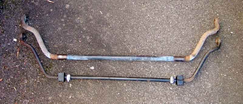
The PO fitted one of the Ron Hopkinson handling kits to the V8 in the shape of the rear bar with telescopic dampers and the uprated front bar. It's said that one has to uprate the front when fitting a rear or it induces oversteer. The front bar is 7/8", I've not measured the rear. However when the factory fitted a rear bar for 77 and later models they reused the CB 5/8" bar so that may well just be marketing. For some time I couldn't really tell whether it was making much of a difference (the PO said it did, but he would say that, wouldn't he?) although the back did feel 'different' to my roadster. But whether that was just because I was comparing a CB roadster with an RB V8 I couldn't really say. Then I drove a friends unmodified CB V8 and I could immediately tell it was the same as my roadster i.e. with more movement at the rear as if the rear axle were moving around or the tyres were squirming. But I still didn't know how much of the difference was down to the ARB and how much to the dampers.
April 2007:
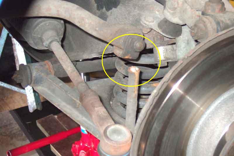
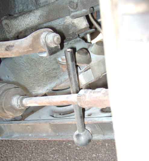
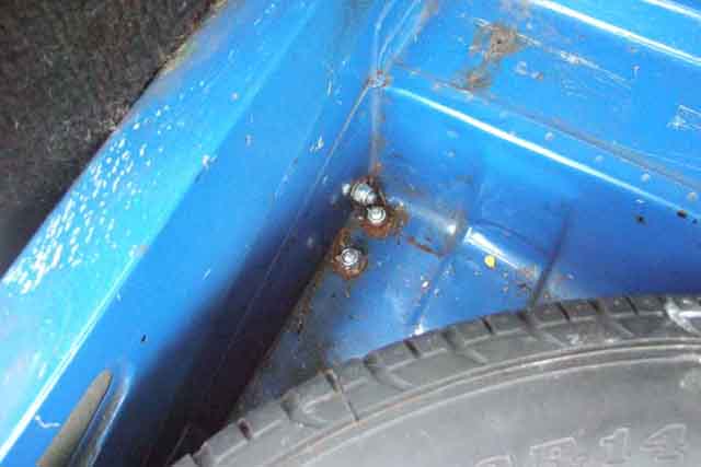 I've had a request from someone who has obtained the RH kit but without instructions and asking for any help I can give on where and how the rear bar mounts. Mine were fitted by the PO so I have no instructions, but I can at least supply some photos and a brief description, click on the thumbnail.
February 2016: Gordon Lewis has kindly supplied me with a scan of the original Ron Hopkinson instructions for front and rear, as he has the same set-up as me.
August 2018: Kevin Poole has also very kindly supplied me with a scan of the rear fitting template. The distances on the template are critical of course in order to get the holes in the right places, and to that end Kevin has drawn a reference line exactly 4" long on the template before he scanned them. When you print this template you will have to measure the line to confirm the printed template is to the correct scale. With my printer and software the default settings produced a line that was only 3.75" long on A4 paper, but I was able to change a setting from 'Fit to page' to 'Actual size' (or a custom setting of 100%), and that came out correctly. However one side of the drawing is clipped as it is now too big for A4 paper in my printer. But if you orientate the page correctly this clipping can be on the side with the narrow taper near the 'scissors' symbol as indicated by the grey shading here, which won't affect the positioning of the holes. If you can only print out one of the templates like that (there are separate ones for each corner of the spare wheel well) then after using the template on the appropriate side, and having punched holes through to mark the floor for drilling, simply turn it over and bend the 'Lay on boot floor' section the other way. Do not clip the other side or you may lose accuracy.
Front bar issues:
One day in the V8 I noticed a grinding on full lock and it turned out to be the rim of the wheel rubbing on the bar. Checked the other lock and it had plenty of clearance, so I gave an exploratory tap on the bar with a lump hammer and it moved sideways a little bit. So I tapped it some more until the clearances were about equal both sides. Now the standard bar on both the V8 and 4-cylinders cars have clamps which sit just inside the pivots and bushes which bolt up to the front apron and so prevent the bar moving from side to side, but mine doesn't have any. Either the PO never fitted them or the Ron Hopkinson kit never provided them. However this is the first time in 9 years and 65k miles so perhaps I do them an injustice. The right-hand (where the rubbing was) front damper has also started leaking recently and although it still seems to be damping normally maybe that has had an effect too. We shall see and if it rubs again after I have changed the damper I will have to investigate some clamps.
Summer 2006: Still grinding, and by this time Colin Parkinson had emailed me to use a 1" length of hose of the appropriate diameter split up one side, and a worm clip clamped round that. Didn't have any suitable hose, but I did have an old inner tube I had already cut into, so I used a 6" (or so) length of 1" width of that, wrapped round the bar several times, and then clamped. We shall see.
Summer 2007: No further grinding, so it looks like a successful mod.
October 2016: Still no grinding, and although I've just been made aware that Brown & Gammons do clamps for 3/4" bars (and other sizes) at �20 a pair ... strips of rubber/split hose and Jubilee clips appeal to me much more!
May 2014: MOT advisory on slight play in the V8 front anti-roll bar bushes. Checked the lower joint to the A-arms first but that was fine, then tried the joint between the drop-link and the bar proper and found several millimetres! Took it apart to find virtually no bush left, just a couple of slivers of rubber on the tube and socket. As an after-market bar long out of manufacture I'm not going to be able to get spares, but maybe the bush for the standard bar might fit. Email one of the usual suspects but of course no response. In the meantime I thought it was worth experimenting with one side. Found a bit of hose that is a reasonable fit for both the sleeve and socket, and with a bit of Vaseline, a suitable bolt and washers, can squeeze the three together enough to get the U-fitting at the top of the drop-link over the new bush and insert the bolt. So easy I decided to do the other side as well, and several hundred miles later there is still no play in either.
October 2016 Subsequently I see these bushes from Brown & Gammons. As the drop-link is the same for the standard and uprated bar, I'm assuming the bolt and hence the ID if the bush is also the same. An enquiry may elicit a response as to whether the OD is the same.
May 2022: B&G have poly chassis mount rubbers for 7/8" and other bars.
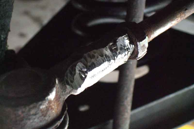
 Driving round the block to warm up the oil prior to Vee's service I suddenly started hearing this intermittent loud rattle on the left that seemed towards the rear, that sounded more structural than something loose in the car. My first thought was loose wheel nuts but they were all OK. While the oil was draining I got under the back, poked and prodded but couldn't see or find anything. However as soon as I got under the front to position the jack in preparation for getting the wheels off, I could see the anti-roll bar drop-link had parted company with the bracket on the end of the bar itself! (Interestingly eighteen months later another noise which appeared to be coming from the rear turned out to be a loose front damper). It's going to have to be removed in any event, and I feared the tapered pin would be seized in the A-arm and spring pan as I had experienced before. However that was when I had changed Vee's A-arms because the trunnion holes were ovalled, and as normal I had reassembled with copper-grease so the pin came out with just a tap from a hammer. From the way the link bar had torn away from the bracket and left a shaped hole it was quite easy to see how the two parts had fitted together, so I angle-ground the end of the bar and both faces of the bracket ready for welding.
I was pondering how best to clamp the two together for welding, but as the alignment of the bar and the bracket is angled, I decided to refit the parts temporarily and tack-weld them in-situ. If the angle was out by even a small amount there would be a constant twisting force on the bush around the pin, as well as the bush in the arm. I placed some pieces of hardboard around the joint to protect surrounding areas from weld splatter, levered the bracket down onto the bar, and applied a couple of welds. They seemed secure to I removed the drop-link and finished the welding and clean-up in the vice, and reinstalled it. While working on this I had noticed that the bush I had replaced in May 2014 showed no signs of wear, so that had been a successful repair.
Would my weld repair hold? If it broke again I would need to replace the drop-link. Initially I thought that as a Ron Hopkinson part spares went NLA years ago, which may mean retro-fitting a standard bar, which would mean removal of the rear bar. But while writing this I realised I had been sent a copy of the instructions, which state that the original drop-links are retained, and so are standard items which does make sense.
June 2016: It did break again, partly down to my welding I suppose, the fact that my welder is more applicable to panels, and the RH front bar is thicker than standard so puts more stress on the drop-links, so I ordered a new one. Ordered Sunday morning it arrived Tuesday morning and only took half an hour to fit, and at �10 didn't break the bank.
October 2017: Checking the near-side damper bolts for tightness (found the off-side were loose and causing a clonk) I found the drop-link broken again! Only 15 months old, but for 12 of those Vee was off the road in restoration, it has only done 1000 miles, 500 of which were some longish trips on good roads. Looked up my records to see it was supplied by Moss, who on their description page today say they are made by the original manufacturer, pull-tested to 3/4 ton.
 It's interesting to note that the broken end shows the same minimal weld across barely half the diameter of the end of the bar, with no external signs of welding, so quite possibly a type of spot-weld where the two parts are held together and a very large current passed through the joint, rather than with an arc and adding metal with rod or wire.
I started looking at replacements again, and find the price varies from less than �7 at Motaclan/Leacy and more than �15 at B&G, so a 100% (from the cheaper item) range. Some of them looked like they may have some weld where the bar joins the bracket, so starting with Motaclan/Leacy I asked them if they could have a look at one of theirs. Always very obliging they did, and after a pause he said "There's no sign of a weld at all!". Even more obliging he said that there might be more than one manufacturer, and would ring round the other suppliers to see what he could find.
 In the meantime I contacted Moss and explained the situation, when I bought it and the use it has had etc. Although I couldn't find the invoice I do have a record of the date so gave that, and next day I get an apology saying they will send me a replacement. (Better service than B&G who supplied an incorrect release bearing for the V8 but despite it being unused refused to do anything about it having had it more than 12 months). On arrival that seems to be the same i.e. no signs of weld around the join.
I have repaired my original again, this time taking more care over the welding. However now I have the FOC replacement I'm going to see about getting it seam-welded where the rod butts up against the bottom of the bracket, so will have what should be a stronger replacement when my repair fails again.
Why so sure it will fail again? Where I live it is impossible to drive anywhere without going over a series of traffic-calming measures. The full-width tarmac ones are bad enough, but there are a number of the fantastically inappropriately named 'pillows', anywhere between one and five depending where I'm going. These are large rectangular slabs of concrete, one in the middle of each lane, with all four sides sloping straight up to a sharp edge before the flat top. If nothing is coming the other way then I can drive between the pillows, and reduce the effect by half as with the relatively narrow track the wheels are only part-way up the sloping sides, and both wheels go up and down about the same amount. But if there is someone coming the other way I can't do that. Neither can I go straight over the top as the exhaust catches the sharp edge around the flat top in both the MGBs. What makes it worse is that even the entry edge of these stands proud of the tarmac - either the tarmac has sunk a bit or they were never installed low enough in the first place - which makes the problem even worse. So other than waiting until the coast is clear and driving up the middle (and annoying following vehicles), I've been driving with the near-side wheel in the gutter, which means the exhaust clears it. However that tends to push the off-side wheel up and the near-side wheel down, as the rear wheels are still level, which puts the off-side drop-link in compression and the near-side in tension ... i.e. tending to pull it apart! Added to that the PO fitted a Ron Hopkinson rear bar, which apparently necessitates an uprated front bar. So with the uprated front bar there is even more tension on the near-side drop-link, as the bar needs more force to twist it by the same amount. Whilst I can comfortably drive over most of the tarmac full-width strips at nearly 20mph (most of them are in a 20mph zone because of schools) with these pillows especially when I can't drive between them I'm having to creep over them at less than walking-pace, so it's hardly me 'abusing' my suspension. What's really annoying is that some drivers can race over these well in excess of 30mph (20mph zone remember) with impunity, and I've had people overtaking me when I have to slow right down. I complained to the local Council about one of the tarmac strips in the past, as for some reason the rising and falling ramps were only half as long as any of the others, which made them twice as severe and steeper than the guidelines state. They did correct that, so I shall have a go at them about these pillows.
The other possibility is to replace the uprated front bar with an original, which in theory means I would have to remove the rear bar, although when the factory fitted a rear bar they only uprated the front bar from 9/16" to 5/8". However all three times it has broken, effectively meaning no front ARB at all, the only thing I have been aware of on one of the occasions was a noise from the end of the bar hitting the bracket! The other times nothing at all. So for my driving style at least, hardly essential. The original RB V8 item was 9/16" and common to 4-cylinder RB cars, and although it is NLA there might be a possibility of getting a used one.
November 2017: Scanning eBay I find a 5/8" BHH882 bar for sale at �24.95 + �9.95 P&P so go for it. 1/16" thicker than the original RB V8 bar, but these were used on CB V8s, and a full 1/4" less than the existing one. I wonder about the bushes, and there is an ad on the same page for a pair at �5.10 + �1.95 P&P which didn't seem too bad. But when I started looking at the usual suspects they are �1.20 each plus P&P, and I'll see what they are like first (good). No clamps (to stop the bar moving from side to side) shown, and they (21H667 and 668) are NLA (although the 9/16" ones AHH6546 are available). The RH bar never had them but the bodge worked, so I shall just re-bodge the replacement bar. I do wonder whether 1/32" can be shaved off each of the smaller ones though ... I'll also need new mounting bushes, but they also seem to be available - AHH6541 9/16", 1B4526 5/8", and AHH7927 3/4", all of which use the same clamp. Those three do use the same angular clamp, but I had forgotten the RH uses a half-moon clamp! I'll fit the replacement bar using those, but I suspect they will clamp the rubbers too tightly onto the bar and may well squeak, so will get the correct 'straps' BHH2000 in due course. Being a thinner bar I have some hose that will fit with smaller Jubilee clips to prevent the bar moving from side to side, which is neater than the previous bodge using strips of old inner tube.
 Getting underneath I did wonder if I would have enough room to manoeuvre the bars out and in over the bottom hose i.e. would there be enough room below the car and to the side, but there was plenty. Getting the new one fitted was a bit of a fiddle. First I couldn't get the bolt through the eye and the repaired drop-link bracket, and had to remove the drop-link to see what was happening. The replacement bar is more bulbous where it sits in the bracket, and was fouling the additional weld going through a hole in the bracket to the end of the bar, filing that down a bit was all that was needed. Next having forgotten the RH pivot bush straps are half-moon shaped whereas the originals are angular, so not a direct fit, I had to use a jack to lift the straps up a bit compressing the rubber to get the bolts started. As the P&P is more than the correct straps, it can wait for a supplier visit. Annoying, as I had already had to order new pivot rubbers and pay a high P&P, buying the two lots together would probably not have cost any more.
January 2018:
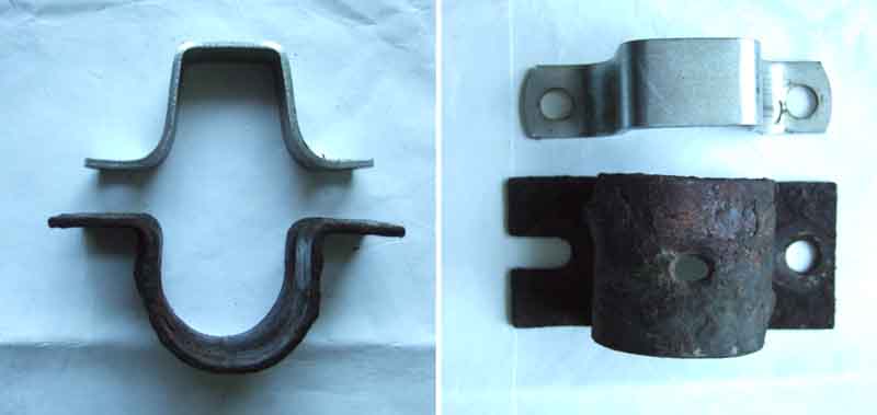 No problems with the RH straps on the factory pivot bushes but a trip to Motaclan/Leacy to get a replacement front damper for Vee (weeping since I started using her again) so took the opportunity to pick up a couple of ARB straps, and some A-arm bushes as one of them has a chunk of rubber sticking out. Damper refitted so easily I decided to replace the ARB straps ... but just doing one took longer than the damper in an awkward space, so I left the other pending better access. The problem is that whereas the RH straps have a slot one side so automatically fit the hole spacing in the chassis rail, the original type just have holes, and these have to be exactly aligned with the chassis rails holes or you can't get the second bolt started. So first step is to offer them up without the bushes in the way, and squeeze them up in a vice to get the correct spacing. Next the straps have to be pushed hard onto the bush, and even the bush compressed a bit, to get the second bolt started as ideally they would be 1/4" longer. Even with the matching bushes and straps they still need to be jacked up into position.
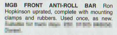
February 2018: I couldn't help laughing when I read this in the latest MGOC magazine:
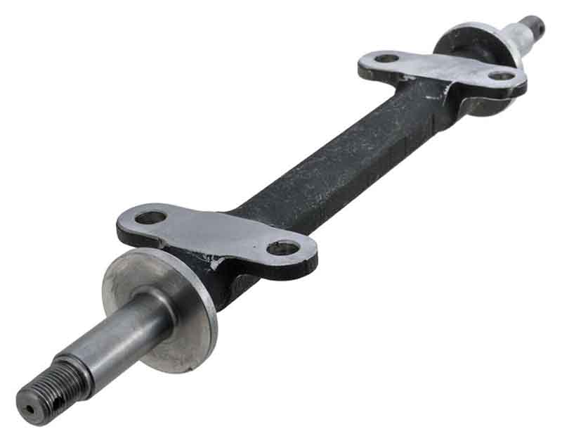
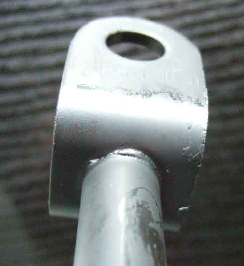
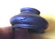
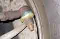
 In 2003 or so I became aware of a rattle from the back of the car. When I checked I found that both of the ARB drop-links had snapped where they connect to the bar itself. When I got them off I could see there was a pin on top of the drop-link that goes through a large dished washer, rubber bush, the eye on the bar, another bush and washer and a Nyloc nut holding it all together. The pin had thinned due to corrosion, eventually snapping, click on the picture at the left to enlarge. They had been on the car some eight years and 65k miles of all weathers but even so I thought it was a bit soon for suspension components to corrode and break. However the rear of the car suddenly felt like an unmodified car again, indicating that the improvement came from the ARB and not the telescopic dampers.
 Ron Hopkinson used to be located in Derby but Moss UK in Derby has taken over the distribution. I ordered a pair of drop links and new nuts, together with two bushes and washers which had been lost, one from each side. The rubber bushes being compressible, and with no instructions, I erred on the side of tightness and when fitting the new parts tightened down the nuts quite a bit. I also daubed the parts in Waxoyl to hopefully reduce any subsequent corrosion. Immediately the rear handling was restored and I went merrily on my way. However about 100 miles down the road I had just done a bit of enthusiastic overtaking when I heard a bump, looked in my rear view mirror, and saw something bounding off into the undergrowth. When I checked underneath sure enough the new pin had snapped but this time I had lost both bushes and washers from that side as it had snapped right at the base of the pin and not part way up as before, see the picture on the left.
I got on the phone to Russ at Moss, who asked me to return the broken drop-link, then he sent me a new pin, bushes and washers at no charge saying he wasn't surprised it had broken given the design of the drop-link with its sharp angle. However after the failure of the new drop-link I had a close look at the ARB and realised there is a significant design weakness in the Ron Hopkinson design as a whole and not just the drop-link. If you look at the factory bars where it joins the drop-links you can see there is a joint that allows the drop-link to swivel back and fore freely, and this is important because as the axle goes up and down the angle between the drop-link and the ARB is continually changing. But with the RH arrangement the only movement that can take place is by distorting the upper rubber bushes which themselves are trying to bend the upper pins of the drop-link back and fore. So this time I made what movement there is as easy as possibly by only tightening the nuts enough to fully engage the nylon on the Nyloc nuts. But even sooner this time it seemed, the drop-link on the right-hand side broke yet again, this time while travelling in a straight line but over some undulations.
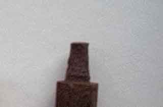
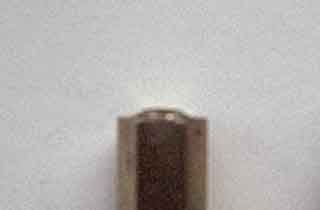
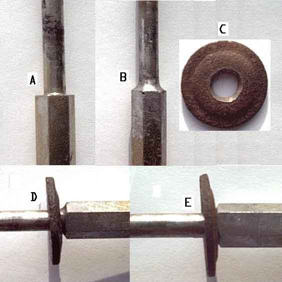 Another phone call to Moss and another free drop-link, bushes and washers, but this time they sent yellow poly bushes instead of black rubber. These are much harder than rubber so I would imagine they would break the pins even quicker. Fortunately I had enough rubber bushes left for the top and used the yellow ones on the bottom where there is less bending movement. I decided to try and strengthen the pins by welding and grinding at the base to form a radius instead of a right-angle, you can see the before and after as A and B in the picture on the left. I also cut a chamfer into the base of the bottom washer (C in the picture) so that it sat right at the base of the pin and not up on my weld (D and E before and after). Furthermore I have tried to make the bushes more compliant by shaping the inner hole into a cone rather than the original cylinder, in the hope that this would impart less bending force to the pin. Time will tell, but if one of these breaks again then short of coming up with a completely different joint that allows free pivoting of the drop-link to the bar, I shall have to junk it all.
May 2005: Some 18 months and 4k miles later, and prompted by an enquiry from someone else who has had the same failure, they seem to be holding up, and that includes a reasonable amount of using the power and working the suspension. Someone else reported a while ago that they only just nipped up the nuts and have had no problem, but as mentioned above when I did that on the 2nd replacements they broke even sooner than the 1st replacements. An alternative to doing away with a rear ARB altogether might be to fit the factory system recovered off a scrapped car. The joints at the ends of the bar (which freely articulate) could well be worn and loose but I note they are now available again. Another possibility might be to machine the ends of the RH bar to accept the screw-on factory end joints.
February 2018: Gary Roberts and I have been emailing back and fore about the RH kit, and he has found reference to an updated version on the Moss Europe site - Evolution 2 kit EHK101. They are not currently available (and the Moss US part number given does not exist on that site, or this kit) but there are fitting instructions which he forwarded to me. Looking at the drawings and reading the instructions under 'Roll Bar Links' it is evident that rather than the fixing holes for the links - and the studs on the links - both being vertical as on mine, they are now horizontal. This makes them the same as the damper drop-links i.e. relatively free pivots with no bending moment.
Clonk when Braking August 2018
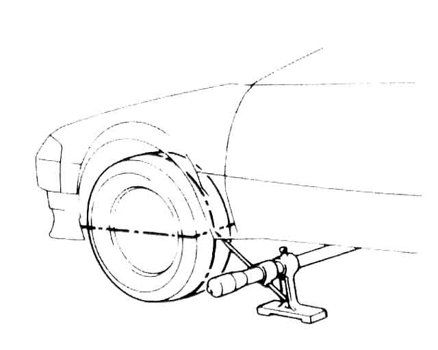
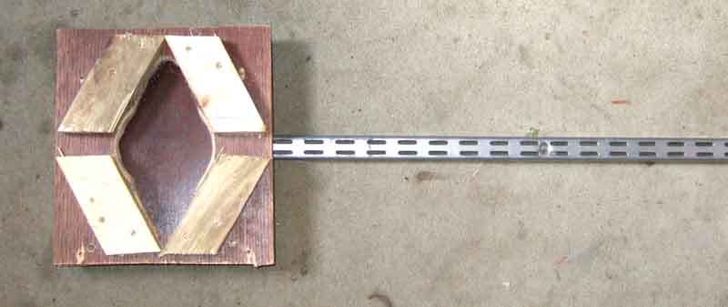 The problem was how to do that while looking round the back of the wheel at the suspension components. I would need a pal, but rather than have him grasp the wheel and heave I decided to make something like the eared spinner 'spanner' which would give more leverage on the wheel and make the job easier. Cut out a template from card held against the spinner and drawn round, marked up some gash board shelving, cut out the shape, and screwed a length of angle iron to it. Applied it to the spinner and sure enough relatively gentle levering reproduced the clonk. While I was at it I thought I'd try the other side ... and the cut-out didn't fit as I had shaped it for the asymmetric spinner on the off-side! No matter, a few minutes later I had a 'universal' spinner spanner, but no clonk from the other side.
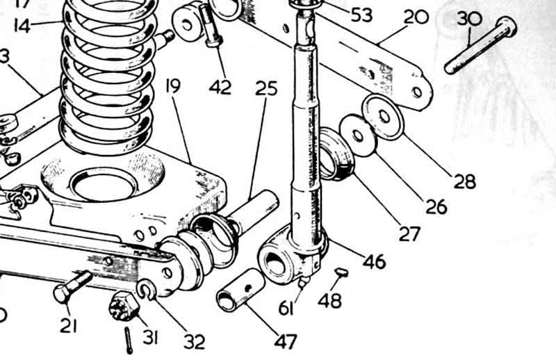 While waiting for said pal to arrive I pondered some more, looking at the drawings of the front suspension assembly to see if I could work out what the source might be, and the main contender was the lower king-pin trunnion sliding back and fore on the distance tube. Pal duly arrived, did the levering, and that's exactly what is happening. The distance tube itself is supposed to be tightly clamped between the thrust washers, but there is a rotation between the king-pin bush and the inner faces of the thrust washers as the suspension moves up and down and the king-pin bush pivots about the distance tube. Grease is supposed to be forced into the lower nipple to the inside of the bush, and then spread outwards to the ends, and the thrust washers, to be retained by the grease seal. With the lower trunnion moving back and fore on the distance tube it could be one of several things:
- Lower link bolt not tight
- Ends of the bush worn
- Thrust washers at the ends of the distance tube worn
- Anything else?
- New lower trunnion kit? Supposing it's the bush?
- New king-pin bush? That needs reaming
- New king-pin? That means complete strip-down of swivel axle assembly, almost certainly a new upper trunnion kit, and maybe a lower
- Replace the swivel axle wholesale? Expensive, and means re-shimming the hub
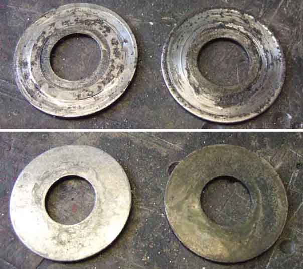 Then cleaning up the thrust washers clearly shows wear marks on the face that has been against the king-pin eye, and they can be felt with a finger-nail. New lower trunnion kit? The rubber grease seals are old but still holding their shape, and it means ordering and waiting for a kit. As there is no wear where the thrust washers bolt up to the distance tube, or to the grease seal support (to be honest I have no idea why the support is there, it's the same size as the thrust washer and flat against it), surely if I just turn each washer round it will present new faces to the king-pin bush? The effect of wear on the (now) back of the thrust washer where it is against the seal support should be negligible. So based on nothing lost if I do that, that is what I do. Pull the trunnion away from the ends of the A-arms, reassemble the seal, seal support and thrust washer against the ends of the distance tube, and slide the trunnion back between the A-arms. Peering through and fine-tuning of the jack height gets the holes aligned to I can get the link bolt back in, and refit the nut. Jack down and heave on the wheel and no clonk. But having been disassembled and reassembled maybe things need time to settle back into position, so take Bee out for a drive. A few miles test braking where I can, and still no clonk, nor some time later on a longer trip!
The trunnion dust seals may need replacement but beware. If they are reusable then I would as replacements have a reputation for failing in a few months. One person claimed one of the suppliers had neoprene versions, but these expanded in use so didn't retain grease and let dirt in, and needed annual replacement. A year later he was recommending them, and when questioned stated that although they are the same part number they have changed and are now better - Moss Europe AAA1323X, Caveat Emptor!
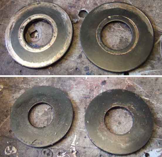 Flushed with success and as it only took half an hour at most, I decide to tackle Vee as well. Hers is less noticeable, and seems to be coming from the near side. Pulling on the wheel reproduces it, I don't have the equivalent of the 'spinner spanner' for her stud-mounted alloys, but then knowing what I know now I don't need it. Vee has a castellated nut and split-pin which takes a few minutes to fiddle out from behind the brake back-plate, but with the thrust washers out they show similar wear to Bee's, although not to the same extent. But turned round, all refitted, and another test-drive, and no clonk! Doubly chuffed.
Track Rod Ends
Front adjustment
Measurements: A huge variation 'on the road', as it were:
| Axle Type | Wheel Type | Length | Rear Track | Front Track | Note |
| Banjo | Disc | 46.25" | 49.25" (1250mm) | 49" (1244mm) | 1 |
| Wire | 44.5" | 49.25" (1250mm) | 49.25" (1250mm) | 1 | |
| Salisbury/Tube | Rostyle (late) | 48.5" | 1264mm | 1247mm | 2 |
| Wires (late) | 47" | 1250mm | 1244mm | 2 | |
| Dunlop Wires | 47" | 1270mm | 1273mm | 3 | |
| Rostyle (early) | 48.5" | 1252mm | 1235mm | 4 | |
| V8 alloy | 48.5" | 1250mm | 1252mm | 5 | |
| Early Rostyle on V8 | 48.5" | 1252mm | 1254mm | 6 | |
| 72 spoke wires | 47" | 1250mm | 1220mm | 7 | |
| 60 spoke wires | 47" | 1256mm | - | 8 | |
| Minotaur Minilites | 1260mm | - | |||
| 15" alloys | 1278mm | - | 10 | ||
| Aftermarket wires | 1268mm | 1273mm | 11 | ||
| MGC wires | 1267mm | 1287mm | 12 |
- Workshop Manual for G/GA engines
- 1977 LHD Workshop Manual and 1978 Repair Operation Manual. However one would expect the Salisbury Rostyle front track to have increased by the same amount as the rear, i.e. to 1258mm whereas it's only 3mm wider than the Banjo disc wheels, although it's complicated by the change to V8 hubs from the same date. For wires one would expect 1262mm for the rear track and 1256m for the front track given Clausager's comments on pages 95 and 150 about a modified wire wheel from September 76 "BHH2133 instead of AHH6487, new wheel has 9/16" (14.3mm) inset to improve tyre clearance to wheelarch". However I don't understand why the wire wheel would need more clearance in September 76, when the Rostyle wheel had the offset (and hence the clearance) reduced to give a wider track, which the higher ride height of rubber bumper cars would allow for without rubbing. Indications are that the earlier wheel had a 21mm inset i.e. a 6.7mm change per wheel.
- My after-market Dunlops on a standard wire wheel axle and front hubs, i.e. 20mm and 29mm more than the factory figures.
- Early Rostyle estimation based on the above reduction in offset from 28 to 22mm i.e. a 6mm change per wheel.
- My V8 alloys.
- My V8 with 28mm Rostyle wheels.
- Michael Beswick - front 30mm narrower.
- David Corrie.
- Ben Purnell.
- Steve Livesley - RB, 185 tyres. Rubs occasionally two-up.
- Richard Towers - MGB converted to wires
- Richard Towers - MGC with 15" 5.5 wires
June 2020: An article on building a steel-wing Sebring replica in 'Enjoying MG' included the comment that the first time they put the car on wheels they had to hand, the clearance to one arch was 10mm less than the other, which eventually was found to be down to two different wire wheels. That 10mm per wheel, or 20mm difference in the track, is exactly what I have.
In the meantime I've done a measurement between wheel mounting surfaces using my tracking gauge, which comes out at 1320mm.
More information on wheel sizes and offsets/insets here, and on converting from stud wheels to centre-lock here.
Removal
Front Track Alignment
Track Width
May 2017: Following a comment on the MGOC forum I learnt that there have been two types of steering arm and track-rod end. What the Workshop Manual describes as 'early production cars' had a washer under the nut securing the TRE to the steering arm. Later cars had a narrower hole in the arm, the TRE pin was longer, and the nut is deeper, and no washer. The later TREs can be fitted to the early arms, just leave the washer out. The change must have been pretty early as there is only one RHD and one LHD part number for chrome bumper TREs and one (per side) for steering arms in my Parts Catalogues. The catalogue does list five part numbers though:
Dust covers: Damaged dust covers are apparently an MOT failure, and are available separately, but like so many parts these days - rubber in particular - fail very quickly. Someone on one of the fora claimed he had silicone rubber and they are much better but didn't give a source at the time. Googling revealed only one source - an eBay seller in Bulgaria, but the size quoted is much bigger than quoted elsewhere for non-silicone rubber for the MGB and I couldn't find them elsewhere in his 'shop'. Subsequently the poster came back with a link (NLA) to the correct size 13-31-23 from said Bulgarian source.
April 2019:
 Finding one of the covers on my RB V8 slightly damaged with the larger retaining spring distorted I took the dust cover off to check the sizing, and find it significantly different: The pin is 11.6mm diameter, the groove in the socket is 30.33 dia, and the depth between the socket groove and the start of the straight section of the pin is 16.6mm. The existing dust cover is very similar to those measurements for the pin and socket groove, and the depth is 18.8mm i.e. 12-31-17. So although the two diameters of the 13-31-23 are fine the depth is quite a bit more, and the excess material would end up being crushed and maybe not lasting very long. The closest the supplier has is 12-31-21 in 'high quality rubber' but clicking on that displays an error page, and it also looks to be a completely different shape. The next closest is 12-31-22 with the same shape as the existing ones, but is described as 'polyurethane', and priced in American dollars. I am awaiting a response from the supplier. Update: As with so many people these days he seemed incapable of answering several questions asked in one email, saying all types were available. Googling showed up other sources but 'universal', and rubber, so I ordered a pair of the poly ones and will see how I get on. Retaining springs not available, but by disconnecting the TRE from the steering arm I was able to remove the cover and retainer (flat, not round wire as with the smaller retainer), 'straighten' the retainer and refit with one of the replacement covers. Some say they use cable-ties, but even the small ones are quite a bit bigger than the springs. Fine on track-rod gaiters, but on these I'm not so sure.
May 2020:
 12 months later still there and no signs of deterioration.
Removal:
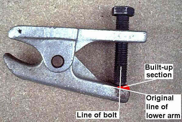 Using wedges and pickle-fork so-called ball-joint splitters I had never been able to disconnect the track-rod end (TRE) from the steering arm without damaging the rubber boots on them i.e. destroying them in the process so unless I was changing them anyway I didn't even try. To replace them you will have to disconnect them from the steering arms of course, but to replace just the gaiter you can either unbolt the steering arm from the swivel axle which is easily done then unscrew the TRE with steering arm from the track-rod, or just unscrew the track-rod from the TRE rather than vice-versa. You may have to remove the tie or clamp on the small end of the gaiter in order to turn the rod without twisting up the gaiter. Eventually I bought a ball joint separator but had to modify it. Now splitting track-rod end tapers is a positive joy.
Update August 2010:A tip when disconnecting the track-rod ends from the steering arms. The nut is usually a Nyloc, and the effect of this is that once the taper is broken you can't turn the nut on the thread without locking the taper again, as the stud just turns in the ball-joint. And if using a screw-type splitter you really need to have a nut on several threads if you are to avoid damaging the end of the stud. The tip is to remove the Nyloc nut, then put a plain nut on until the end of the stud is close to the face of the nut, before using the splitter. As long as the threads are good the plain nut will be much easier to remove once the taper is broken. For replacement the same problem occurs, so screw the plain nut up tight to lock the taper, then replace with the Nyloc nut.
But I digress. Make alignment marks on the track-rod and TRE. Slacken the lock-nut and count how many turns are needed to separate the track rod end from the track rod. If refitting the same TREs then using the same number of turns you should be spot-on, but unless you know your tracking was right before there is no harm in getting it checked, and you know you will be able to slacken and adjust everything before it all seizes up again (and if you reassemble with copper grease it is much less likely to seize-up anyway).
 If changing track rod ends and they are basically the same length alignment marks and counting turns will probably get you close enough to drive straight (hopefully!) to an alignment centre, which should be done as there are bound to be dimensional differences between old and new track rod ends. However changing Bee's track-rod ends I found the new ones were quite a bit longer than the old, so no point. I measured the difference as best I could at 6mm, then screwed the lock-nuts back towards the gaiters until there was a 6mm gap to the ends of the old track-rod ends, and removed them.
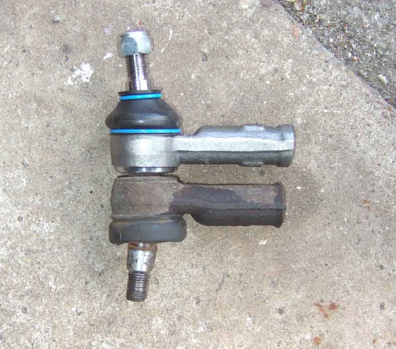
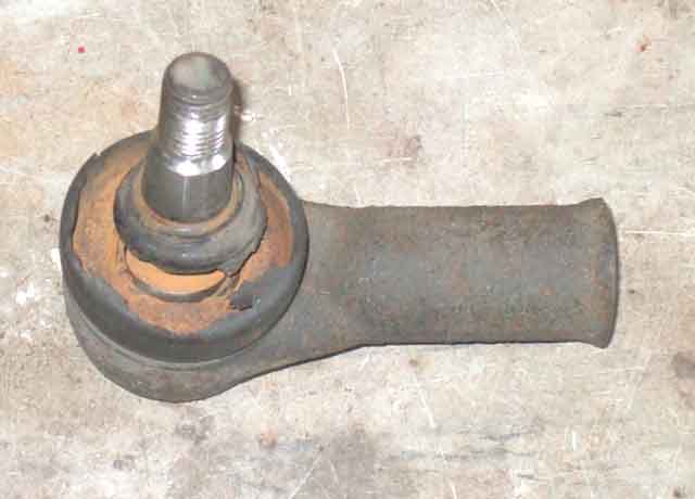 The old ones were surprisingly bad given they were only advisories, the worst had lost a large part of its rubber boot, the ball was sloppy in its joint and rusty. The other one had a split boot and was rusty inside, but the ball wasn't as loose. I then screwed the new ones on right up to the lock-nuts. Not happy that I had got the tracking close enough for driving to the alignment place I decided to make an alignment gauge. Having (hopefully) got the tracking close enough for a test drive it was immediately noticeable how smooth the steering was, I had recently been aware of some vibration through the wheel, which wasn't consistent so I didn't think it was wheel balance. Also quieter, as if I had subconsciously noted some rattling, both must have been coming from the worn UJ as well as track-rod ends. I suppose it is a case of not noticing gradual changes in sound and feel over a long time, whereas we should all be aware of sudden changes and either know what they are (as in this case) or investigate them - Nory's "Listen to your car, it is talking to you".
 Just after replacing Bee's I find that Vee's need doing as well, as a result of investigating a clonk when applying and releasing the brakes, which led me to discover a clonk as I turned the steering wheel back and fore with the road wheels on the ground, which felt like it was the track-rod end but could be the rack! But this time the offside at least looks heavily corroded. I buy two more track-rod ends plus lock-nuts as it looks I might have to use an angle-grinder on both. I don't have a spanner that fits, and my mini-Stilsons isn't giving me enough leverage as well as chewing up the nut, so a trip to Halfords with a new nut gets me a 22mm which is a pretty close fit. That gets the nut turning on the track-rod, but the track-rod is stuck fast in the track-rod end. My Stilsons grip the track-rod to some extent, and a large ring-spanner over the end of the handle gives me more leverage, but being round bar eventually it just slips, even having applied Halfords 'shock and oh' releasing fluid ('shock' from the freezing spray as well as the penetrating fluid, 'oh' from the 'oh bugger' when it doesn't make any difference). So nothing for it but to run the angle-grinder along the length of the track-rod end until the tips of the threads just start to appear. Get the Stilsons on the track-rod again, hoping the heat from the angle-grinding might have done the trick, with more freezer spray on the exposed threads, but still no go. So this time I put the Stilsons on the end of the track-rod end, pin still in the steering arm, in such a way that it is trying to peel it open, and finally hear a 'crack'. After that it comes off relatively easily, only took a couple of hours... New and old look to be the same lengths, so count the turns to remove (21) and fit the new one (with copper-grease!). I decide to leave the old nut on, screwed back a bit, plus a new one, thinking that in future the two nuts locked together will give me more purchase to turn the track-rod.
When I come to do the second one I don't have much time but put the spanner on the locknut just to see what happens and it moves straight-away. Not only that it is screwing the track-rod out of the track-rod end. So crack the taper to the steering arm, unscrew (18 turns), and screw the new one on. This one already has copper-grease on it, I'd forgotten I had already dealt with that one some years ago when replacing a gaiter. Shows just how effective the grease is, and second nut on the other side obviously not required. This one takes me 10 minutes start to finish! All I have to do now is check and adjust the tracking with my gauge. Well, I say 'all', but having gone from king-pins to track-rod ends and noticing a broken bump-rubber on the way, this time I noticed the A-arms on the left side weren't being held centrally on the bushes on the wishbone pivot, but were both as far back as they could go, the front one up against the face of the pivot and the rear one against the retaining washer. Annoying as I replaced A-arms and bushes a few years ago and they are the correct V8 ones. In theory this might have altered the suspension geometry, which could account for a very slight drift to the left on a flat surface, which implies a difference in castor angle between sides. But the direction the A-arms have moved is rearwards, which would have reduced the castor angle that side, which in theory should cause a drift to the right. So something else to investigate further. Used the alignment gauge again, the kit at my local tyre place should fit the V8 wheels OK as a double-check. But just like Bee it was immediately noticeable how much quieter and smoother the steering had become. After finally getting the wheels balanced correctly I was left with an occasional tremor over some surfaces, which I put down to the slight wear that I know exists in the rack, and the free-play in the column. On a 70 miles run there was absolutely nothing - excellent result.
Front Track Adjustment:
Making an alignment gauge, but first some points about tracking and alignment:
Tracking can be measured in one of two ways - physical measurement of the tyres and wheels, or the amount of scrub. I've never used it but Gunson's Trakrite measures the scrub, or side-slip, by pushing the car forwards with one wheel over the device which consists of two plates, one on top of the other, with ball-bearings between them. Any scrub will tend to push the top plate sideways relative to the bottom plate, and this relative movement is displayed on a scale. You adjust the tracking (both track-rod ends equally remember) to give zero scrub or as close as you can get, my Celica manual for example quotes a maximum of 3mm per meter, or 0.118" in 3.3 feet(!) in either direction. You only have to measure one side, as the grip between the tyre and the ground on the other side will push or pull the tested tyre the whole amount of the scrub for both tyres. Therefore get the tested tyre to zero, and the other should be at zero also (however this from Frost advises doing both sides to confirm). Out of interest the toe on the Celica is +-1mm, i.e. neutral or zero toe, which is quite common for front-wheel drive cars.
 As well as describing measuring side-slip or scrub the Celica manual has a detailed description of how to measure the physical amount of toe. Basically you mark the middle of tread, in line with the centre of the axle, on the front or the back of the tyre, and measure the distance between the two marks, which is most easily done with two pointers on a connecting bar resting on the ground. Then roll the car half a revolution, so the marks on the tyres are now on the other side but back in line with the axle centre-line again, and again measure the distance between the two marks. If you carefully move your pointers from the first (reference) position to the second (comparison) position, and line up one pointer with its mark, you can directly measure the total toe between the other mark and its pointer. If you take the reference measurement at the back then roll the car forward to make the comparison, or vice-versa, so the marks aren't scrubbed off on the ground. If adjustment is required this method obviously needs you to move the gauge between the back and the front of the tyres several times, making small adjustments to the pointers each time, and being careful not to knock the pointers when moving from the reference side to the comparison side, in addition to rolling the car back and fore several times (which applies to both methods). The side-slip method will certainly be easier, but at a cost of typically �75 as opposed to perhaps nothing if you have a long enough broom-handle and some thin rod, considerably more expensive for something that may only be used once per year at most.
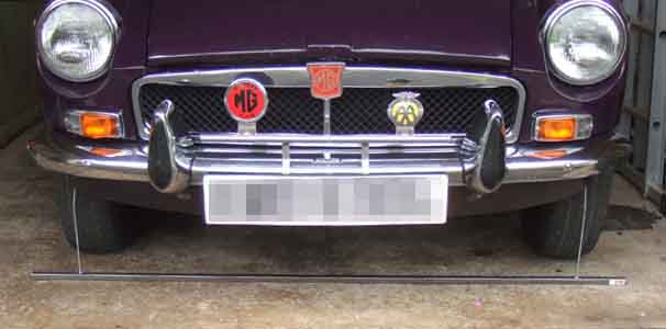 Having recently had a major clear-out of garage and shed I didn't really have the makings without butchering a garden tool or two, so for a few quid I bought some square tubing, threaded rod and nuts from B&Q. I measured the distance between the centre of the treads on each wheel, and this gave me the nominal spacing of the pointers. I also measured the ZS, which is quite a bit wider, and made the bar just long enough to take the pointers at this spacing, in case I ever needed to do that car as well. I drilled hole through the tubing (at the MGB spacing) to take the threaded rod, then overdrilled the bottom hole to allow a cap-nut to pass through which would be on the bottom of each rod. A butterfly nut further up the thread, above the tubing, clamps the rod in position. The rod rises vertically from the tubing and is then bent forwards to meet the mark on the tyre, it's overall length being such that the pointer touches the centre-line of the axle. I subsequently noticed that Moss have a similar gauge at about �50 so quite a bit cheaper than a Trakrite, but not as cheap as mine! However the instructions on the ordering page simply to measure between the outer sidewalls at the front of the tyre, then compare that with the backs. That would require the tyres to be perfectly mounted on the wheels, with no run-out. At the very least the car should be rolled back and fore half a turn so you are comparing the same point on the sidewalls, as I am doing with the centre of the tread.
Subsequently took the car to my local tyre place for a tracking check to find their stuff would not fit over/round the spinners, also my next local place. The fronts could be turned so that with the ears at an angle the laser unit fitted round them, but at the back it is a single central vertical bar and even the body of the spinner sticks out too far for that. Good job I got them (hopefully) close with my home-made gauge, looks like I have a 20 mile drive to the next nearest place with kit that should cope with them. One week later... Some nice weather at long last so a trip through the countryside to a place with screw-in adapters that hold the gizmos further out from the wheel hence clearing the spinner. Tracking is a shade under 2mm toe in, so given that the spec calls for 1.5 to 2.3mm I call that a result! Even more of a result is that checking is free, only adjustment costs!!
Front Crossmember November 2018
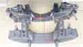 Three types over the life of the MGB - originally AHH6195 on all chrome bumper 4-cylinder cars, then BHH803 on all V8s and RHD rubber bumper 4-cylinder cars, and BHH804 on LHD rubber bumper 4-cylinder cars. The RB versions have a thick spacer under the chassis rails to give the higher front ride height on these cars. The RB rack mounting brackets are also different, and in one case at least angles the rack relative to the crossmember making one end higher than the other ... or does it?
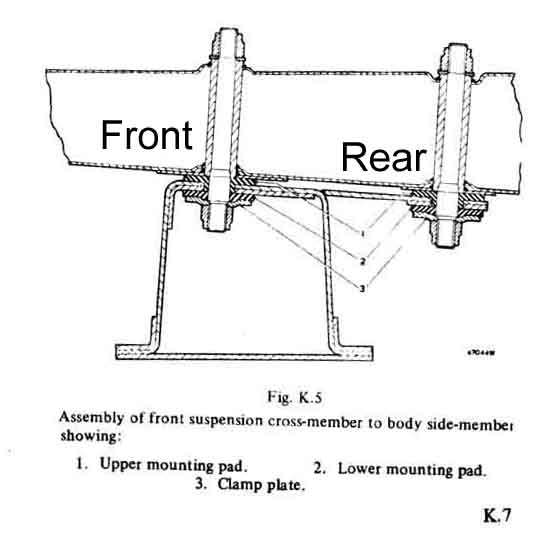 The mounting pads also changed for the later versions. Originally four AHH6205 for the uppers with a collar round the bolt hole projecting down into the crossmember, and four AHH6206 for the lowers which were flat. On rubber bumper cars the front lower pads were replaced with collared pads as there is now space for the collar to project up into the crossmember as well as the upper ones projecting down. The rears are unchanged. For that reason it would appear that all V8s would have lipped pads upper and lower at the front as they had the rubber bumper crossmember throughout, but this isn't shown in the Parts Catalogue or on suppliers websites. The Leyland Parts Catalogue for 1977 and later gives the amended quantities, but whether the change only dated from that point, or whether it was on all rubber bumpers and V8s and simply missed out of the earlier catalogue isn't known. Only Moss Europe (AHH6205SPKC for CB and AHH6205SPKR for RB) and British Parts Northwest (AHH6205/6P for CB and AHH6205/6LP for RB) seem to give a logically correct change point for the quantities with their poly kits.
Castor Angle: July 2023 According to the Workshop Manual this is set at a nominal 7 degrees between 5 degrees and 7.25 degrees, however Don Hayter in his 'MGB Story' writes on page 40 that during the development of the MGB this was "originally designed to give 7 degrees of castor angle, but eventually changed to 4 degrees after testing for optimum steering effort". Curious - a development change that never made it into production for some reason - cost? Or just forgotten?
The steering on the MGB is heavy when stationary and some find it necessary or desirable to install power steering. Others install a castor reduction kit that reduce the angle by tilting the cross-member although whether this only makes when stationary as well as under way isn't clear. I've seen two types of kit - one with square plates that need the crossmember bolts to be removed to fit, and another using tapered 'forks' that only need the bolts to be slackened. Both types need the steering column UJ to be realigned afterwards i.e. column and/or rack shaft positions to be adjusted. I don't see how they can help when stationary when the problem is largely down to the way radial tyres grip the road surface much better than the original cross-plies (the first time I turned a corner in my Mini in the 60s after swapping to radials I nearly went up the kerb!), and I find the slightest forward motion reduces steering effort hugely. Castor wedges will reduce self-centering, and personally for all normal driving I find that is weighted very nicely. Vendors of the kits say things like "The result gives noticeably lighter steering that doesn't load up when cornering" and "They transform the Steering on MGB's - being able to turn corners with just two fingers (instead of a tight grip of both hands)" whereas someone who fitted them writes "Initial feeling is not a massive difference. The steering is definitely lighter going into a corner and a noticeable reduction in self-centering coming out of a corner ... but again not a massive difference". Given Don Haytor's comment it would be interesting to try a car that had them fitted. Incidentally some years ago on this subject someone wrote to Enjoying MG that he was about to buy a smaller diameter steering wheel to reduce the effort ... he would have been disappointed.
Grease cap - Centre-Lock wheel January 2010
According to Clausager V8 front hubs were fitted to 4-cylinder cars from the 1977 model year on. However this doesn't tie-up with front track information in the Workshop Manual and measurements on my V8. The manual states that from 1977 the rear track was 49.75" (1264mm) and the front 48.5" (1247mm), which was when Rostyles with less offset were fitted, i.e. 17mm narrower. But on my V8 with the same axle and apparently the same hubs the front track is 2mm more than the rear. More info on axles and track here, and on wheels and offsets here.
Stud wheel grease cap:
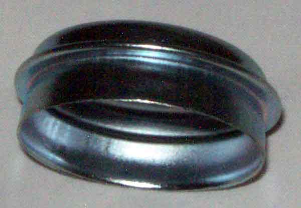 An interference-fit in the hub they can be pretty tight. A sharp-edged drift is needed to get between the flange on the cup and the outer face of the hub to start prising them out, working first one side then the other. The flange means that the cup only goes into the hub about 1/4". Relatively easy to tap back on with a light hammer. My Workshop Manual shows what looks more like a spring-clip, which could be intended to cover a hole through which grease is injected, or to retain a loose cup which isn't shown. However it is described as a cup, and is shown as that in the Parts Catalogue, and is a cup in practice. One person has said his cups are held in with spring clips, but didn't explain further.
Centre-lock grease cap:
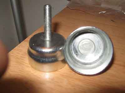 Like the stud-wheel type they can be pretty tight. Unlike the stud-wheel type they are recessed inside the splined part of the hub so less (if any at all) opportunity for prising them out. But there is a threaded stud on the end of the cap which aids removal and refitting. They are a clearance fit down the inside of the splined tube, no flange which would mean the ID of the splined tube would have to be even bigger (which would either reduce the thickness of the wall of the splined tube or mean it would have a larger OD which would impact on the dimensions of the wheel hub). Without the flange they bottom against a shoulder inside the hub, and are inserted about 1/2" before this happens. At a pinch the threaded stud could be gripped by a pair of pliers and pulled and wiggled to get the cap out, but that damages the threads so a more elegant solution is called for.
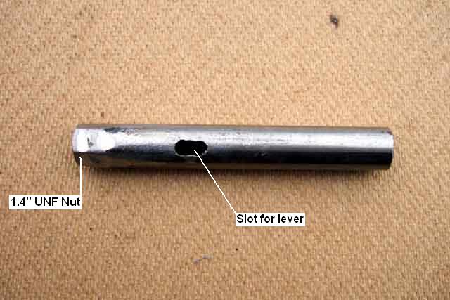 The stud thread is 1/4" UNF, so a nut welded onto the end of a tube or bar, with some means of levering it out once it is screwed in will do the trick. I thought about a couple of lengths of bar pivoted together, but I've got enough volume and weight of tools as it is. So I opted for a length of tubing about 4" long, with a nut welded to one end. A slot drilled in one side to insert the blade of a largish screwdriver, and away we go.
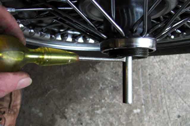 Screw the tube on to the stud until the slot is just about level with the end of the hub, insert screwdriver, and lever. If the slot is too deep in the hub the angle of the screwdriver will tend to try and push the cap to one side rather than levering it off, ditto if the slot isn't in far enough, close to a right-angle will be fine. The cap is pushed in about 3/4" or more so once the cap has started to move you will probably need to remove the screwdriver, screw the tube onto the stud a few more turns, then lever again. For replacement you can either leave the tube on the stud and tap the open end of the tube, or any one of a number of other methods. There is a distinct change in sound from a dull 'thock' to a sharp 'clink' when the cap is fully on.
November 2016: A fora contributor reports that his new grease caps were way too small, thinking they had to be hammered to expand into the hub (like the disc-type engine block core plugs). They don't - early ones may have been fairly loose fitting with a spring to retain them, but the Parts Catalogue and all those I've seen at suppliers and found via Google images are plain and are a light interference fit in the hub. Although my splined tubes have an ID of about 1.87", and grease caps have an OD of 1.845" to 1.85" (being simply pressed sheet they are not precision) the poster's splined tube was more like 2" ID i.e. non-standard. He's found some 50mm trailer grease caps, but they don't have the threaded stud on the end so even if he can get them in he may not get them out again! Neither do they have the flange, which means if he can get them down the splined tubes he stands a chance of getting them in the hub. It also begs the question of what the OD of his splined tube is, and hence the ID of the splined hub of the wheel. If they are standard then the walls of his splined tubes are significantly thinner than standard, with all that implies. If they are larger then he must have non-standard wheels as well.
End-float
Replacement
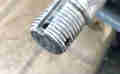 How many holes in the stub axle? Two at right-angles in mine and several Youtube videos but others are adamant that a new (not refurbed) stub axle assembly only has one. With two you only have to tighten the hub nut from the minimum 40 ft lb a maximum of about half a castellation to reach the next hole, with only one you would have to tighten the nut up to a full castellation. Centre-lock wheels have the nut down a long tube which need an access hole in the side to be able to insert the split-pin. Front hubs rotate on the stub-axle of course so only one access hole is need and the hub can be rotated to suit. There are special considerations for rear axle hubs because the hub and the half-shaft rotate as one.
Why end-float?
How do I set end-float?
Why end-float? Updated August 2011
The Factory Manual is quite clear on the need for a particular end-float i.e. 'free play' of 0.002" to 0.004" (2 to 4 thou) to be present with the type of roller bearings used in the MGB. Anyone who tells you to apply a pre-load of 11-15lb ft (i.e. the opposite of end-float) or whatever is wrong. That may be correct for other applications, but not for the MGB. Some say that you don't need shims in the front hubs, some even say you don't even need the spacer. Others say that the act of clamping the inner races, shims and spacer between the hub nut and the base of the axle spindle significantly increases its strength. I can certainly imagine that without shims or spacer the inner race could spin on the axle wrecking it, so personally I prefer to keep things as they came out of the factory.
As to why it's needed, consider the following: The brake disc gets very hot, that is attached to the hub, and when that gets hot it expands along the line of the stub-axle as well as radially, and this longitudinal expansion moves the outer running surfaces of the two bearings further apart. The stub axle should always be cooler than the hub, so won't expand as much, so the inner running surfaces of the two bearings aren't moved apart as much as the outers. If you look at a cross-section of the hub assembly you will see that the outer running surfaces are effectively between the inner running surfaces, and with the differential expansion each outer will be pushed closer to its inner, reducing the gap for the roller. With no running clearance when cold (let alone if there is 'pre-load'), despite the fact that tapered roller bearings are good at taking axial load as well as radial, this will squeeze the roller between the two running surfaces pushing grease out of the bearing and generating significant heat in the bearing itself, both of which will eventually result in premature failure of the bearing. With the correct end-float set when cold, differential expansion will be taken up by the end-float, so protecting the grease film and bearing surfaces.
How do I set end-float? Updated May 2015
It is advisable to have a selection of spare shims to hand before starting the job. There is a base 0.030" (BTB656) then for fine adjustment there are three sizes - .003" (ATB4240), .005" (ATB4241) and .010" (ATB4242). 50 to 55 thou total thickness seems to be the norm, and in the absence of a dial gauge additional shims will be required as below.
- When replacing bearings assemble everything dry first (i.e. without grease) as it keeps things cleaner and is easier to set the end-float. However the oil seal traps the rollers of the inner bearing, so leave this out until the end-float has been set, and the rollers greased, and fitted. This allows the hub to be repeatedly fitted and removed while juggling shims, leaving the inner bearing and spacer on the stub axle, which makes removing and fitting shims much easier, especially on wire-wheel axles.
- The order of parts on the axle is: oil seal collar - inner race of inner bearing - spacer - shims - inner race of outer bearing - bearing retaining washer - nut. Note that the oil seal collar is 'handed' in that there is a chamfer on one inner edge that must go up against the shoulder on the stub-axle.
- The first time you assemble the parts onto the hub leave out the shims and tighten the nut until the bearings bind to fully seat the outer races in the hub.
- Now fit the shims between the spacer and the outer bearing. The objective is to add and subtract combinations of the three thinner shims with the base 0.030" shim until you get an end-float of .002 to .004 which is detected as an audible 'tonk' as you rock the hub or push/pull it in and out. Using combinations and multiples of these thinner shims together with the base shim will give from 45 to 60 thou in 0.001" increments as follows:
- Keep juggling shims until you get two combinations that are only 0.001" apart where the thinner combination gives no end-float and the thicker gives just perceptible end-float. Fit the retaining washer and nut and tighten to 40 ft lb plus the next split-pin hole with the thicker set and check end-float is still just perceptible. If so use the thinner of the two sets i.e. the one that gave no play, add another 0.003" shim, and that should give you the required 0.002" to 0.004" end float.
- If tightening has removed all end-float further juggle shims increasing the thickness by 0.001" at a time until you do have just perceptible play with the nut tightened. Then reduce by 0.001", add a 0.003" and again that should give you the required 0.002" to 0.004" end float.
- When you have determined the correct shims remove the races and inject or press grease in one side only! This Moss page shows how to do this by pressing the roller cage against a blob of grease in the palm (they say heel) of your hand. Keep going till the grease comes out the other side, and leave a bulge of grease on both sides. Don't be tempted to save time by greasing from both sides or you will trap air in the middle of the bearing and possibly cause premature failure. Note that if existing bearings have been removed, washed in petrol or paraffin for inspection, and are being reused, they must be soaked in mineral oil before regreasing. New bearings should already be coated in oil.
- Fill the groove in the oil seal with grease prior to fitting, and the cavity between the oil seal and the inner bearing. Smear the spacer with grease. Don't fill the cavity between the bearings or the grease retaining cap with grease.
Update October 2008:
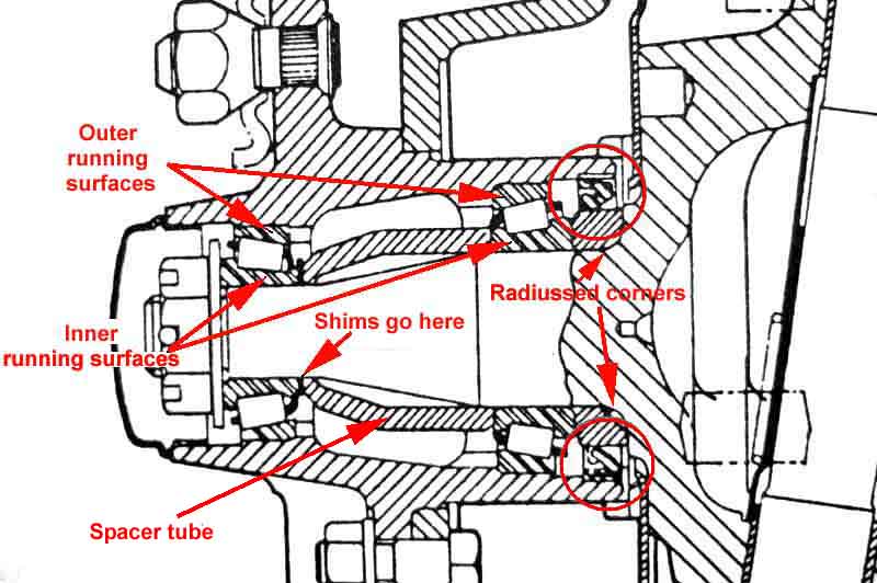 There doesn't seem to be any written description of which way round the oil seal goes in the hub in either the Workshop Manual or Haynes, and whilst Porter does cover it in some editions of his 'Purchase and DIY Restoration of the MGB' or 'MGB Restoration Manual' it seems his description differs from his drawing. My 1989 edition of the former doesn't cover it at all, but Neil from the BBS writes that in his 1992 edition Porter on page 179 says the oil seal should be "fitted to the hub with the lip facing inwards or uppermost in this shot"... but 'the shot' shows the seal facing OUTWARDS, which is indeed uppermost in his picture! So he says it right but shows it wrong. The Workshop Manual does have this photo showing the flat side of the seal facing out from the hub and the grooved side i.e. the lip facing inwards. This is probably deliberate to keep water off the spring that provides the tension on the lip, so preventing it rusting, breaking, and consequently letting water and dirt in and grease out. I believe this to be the standard way to do it i.e. the flat side facing the dirt and the lip facing the oil or grease. Certainly for the rear axle half-shaft oil seals both the Workshop Manual and Haynes say "lip facing inwards".
- Reassemble everything, tighten the nut to 40 lb. ft., then tighten further until a hole in the shaft (there should be two at right-angles to one another) lines up with a slot in the nut. This should occur well before the maximum torque of 70 lb. ft. is reached. Some people say that this additional tightening removes the end-float and to fit additional shims on the outside of the outer bearing until the hole and slots line up at the minimum torque. Personally I have not found that this loss of end-float occurs. However when trying it I did find that fitting shims between outer bearing and locating washer causes slivers of metal to be shaved off the shims when the nut is tightened, because in this position they are resting on the threads of the axle. Slivers of metal are not what you want in your new bearing! If you find this is happening to you I suggest that while juggling shims you tighten to 40 then the next split-pin hole every time, then it won't happen.
| You will see from this that as well as the base 0.030" shim you will need 4 of the 0.003", and 2 each of the 0.005" and 0.010" to make up any combination from 45 to 60 thou. There will almost certainly be some shims in the hub already, but if you make sure you have these as spares before you start you should be fine. |
July 2015: Front Bearing Replacement - by Michael Beswick (with additional comments)
Back home and on the ramp a quick spin of the wheel confirmed it was no better but no worse. The usual suspects all show a bearing kit (inner, outer bearing, oil seal) at about the same price as a single bearing. Being suspicious I wondered about quality. I bought both and was none the wiser- Timken and Toyo were the brand names in the B&G kit.
The car has wire wheels which means that most of the work is carried out down a 4" long tube.....
First off is to remove the brake caliper and tie it up out of the way. Next is removing the grease cap: mine has a threaded stud in the centre so I was able to use a 1 1/4 UNF bolt with a nut just on the end to screw on to the stud. (A second nut acted as a locknut). Out it pulled. Thankfully the split pin was put in a way to make it's unbending and removal easy (see later). Castellated nut size is 1 1/8 AF. Quick tap on the disc edge and the hub pulls free. On a stud-wheel hub the tabbed washer and outer bearing rollers will probably fall out at this point. Note the oil seal collar which will probably remain on the stub axle shaft. (Once when changing a hub I omitted this part-everything wobbled about a bit....)
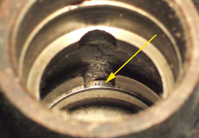 On the wire-wheel hub the outer bearing rollers and tabbed washer are likely to be rolling about inside the hub "tube": the distance piece inside the hub. Levering the oil seal out allows the inner bearing rollers to be removed and then the distance piece. You now have the hub with only the two outer races (tapered collars) that the rollers run on. These need to be drifted out. There are convenient recesses (two at 180 degrees to each other for each race) that allow a long punch to be used against the larger back face of the races. Once these are out it is worth cleaning the whole internal "tube" out.
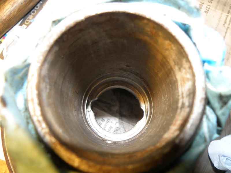 Inserting the new races is more difficult with a wire wheel hub because the outer race is down the 4" tube. A 1 5/16" socket fitted nicely on the (narrow) face of the race - an extension allowed it to be driven home - well nearly. The extension had the usual spring loaded ball bearing to ensure it remained in the socket. This allowed a certain amount of play which negated the "bang" of the hammer. It should be possible to compensate for this, but as I have a mate with an independent garage I went there. They had the correct tool which is very similar: a stepped disc in Aluminium with a central hole and a shaft with a shoulder that fitted in the hole in the disc. Then a big hammer and in it went. The race for the outer bearing is much easier as it is much more accessible, it would need a very large socket so I'd suggest a punch would do it fine - better still if it is ali (or brass, and I have used the old outer race to spread the 'point' load of the hammer round a significant portion of the edge of the new race, tapping alternately on opposite sides. Be absolutely sure you insert the outer races the correct way round i.e. wider face on the inside. Get this wrong and you probably won't be able to drift it out again as the recesses are not deep enough).
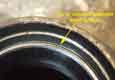 March 2019: It's important to get the races fully seated. The book says to do this by tightening the hub nut with no shims fitted, but there are a couple of ways to be sure. First is that there is a subtle change in tone when drifting the races in and they 'bottom', second is by inspecting the seats from the other side of the hub, looking for a shadow (not seated), and thirdly from the outside looking for the slightly reduced diameter of the hub at the top of the race.
As usually suggested I went for fitting the whole lot "dry" to get the end float correct. This requires the oil seal to be left off (advisable on wire-wheel hubs as otherwise the shims have to be repeatedly removed and replaced down the tube which is a pain). I fitted the inner race, distance piece and the 30 thou shim on to the shaft, and offered up the hub. However you need to be able to hold the hub horizontal with one hand whilst jiggling the outer bearing on to the shaft. A mole wrench clamped loosely (so adjustable) at the top of the disc to the back plate allowed two hands - actually fingers - to insert the bearing. Jiggle the tabbed washer on and tighten to 40 ft lbs + next slot in the castellation nut. It jammed solid..... (NB: when first fitting the hub with new bearings you leave out the shims and tighten to 40 ft lb to fully seat the outer races of both inner and outer bearings).
So remove nut, washer, and ease the hub off. The inner bearing, distance piece, shim remained on the shaft, so I added 21 thou - a guess (Brown & Gammons recommend a starting value of 50-55 i.e. the 30 plus 20-25) - of shims and repeated the operation. Bingo - just the right amount of 'tonk' as described by John Twist. (For those not familiar with the 'tonk' unit of end-float measurement see this setting procedure.) I have used a dial gauge but frankly it was more bother than it was worth.
Undo the lot and grease the bearings in the prescribed manner. I read a Moss Motors document but found I got as much in the hole for the shaft as I did in the race itself. A finger worked as well. Next fit the oil seal having first put in the distance piece. Then it all got a bit more difficult (with the wire-wheel hub, a stud-wheel hub is much easier). Without the oil seal and with the inner bearing on the shaft the shims could be added easily: once the oil seal is in place and the distance piece is flopping about in the "gap", the shims have to be added after the hub has been fitted to the axle shaft (i.e. down the 4" tube), hence the need for the mole wrench to keep it square. I tried all manner of ways to trickle the shims on to the shaft but they get caught on the threads or the shoulder. Eventually I decided to use grease as stiction and fit them to the bearing. I was able to use my finger to line up the bearing square on the and of the shaft and tickle it in. Fitted the tabbed washer and nut....and it jammed solid.
By now there was grease in the system and I had fitted the oil seal so I just kept going (4 attempts) till I got it right. On my axle shaft there was only a single hole for the split pin - not a second at right angles, so I had to use the top end of the torque range to get it to line up. When inserting the split pin do so in a way that the longer leg is facing towards you, and then PULL it a little towards you. It is much easier to push it straight for later removal than trying to get a hook round the back!
So how would I do it next time? Broadly the same: theoretically grease should not compromise the end float, so I am blaming fitter error. However once the oil seal has been fitted trapping the distance piece, fitting shims becomes much more difficult, so I would still use the stiction method-after all grease in there by then.
Front Bump/rebound rubbers Added September 2010
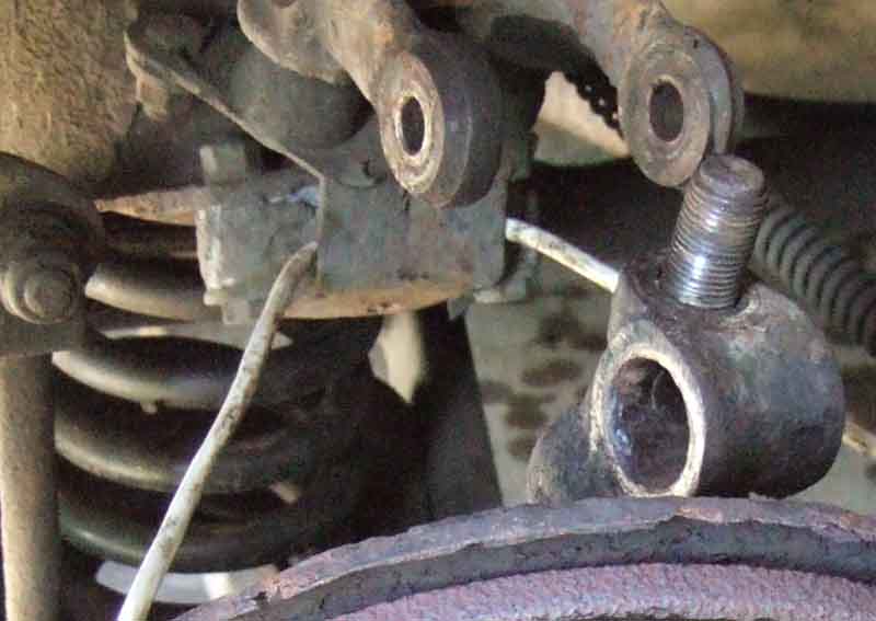 Spotted the bump rubber on the left side was missing from the bracket while working on Vee's king-pins. Got a new one but when removing the old one of course the alloy spacer crumbled quite badly, it was only then I remembered it happening the last time I changed one! It rots really badly - swelling so much it distorts the bracket and even the cross-member mounting point, and because the bolts seize in the spacer the ends around the holes tend to break away. It may also be the swelling against the face that holds the bump rubber that pushes the rubber out of the bracket. So something else to order, but in the meantime I managed to file the worst of the swelling off so it could be refitted temporarily with the new rubbers. The bolts are a bit of a fiddle, you may be able to get a slim ring-spanner on the nuts which are inside the bracket, failing that you will have to use an open-ended. And if that slips off and wrecks the heads they will have to be ground off. Even with a slim ring-spanner you can only undo the nuts part way, as the nuts move up the threads of the bolt they reduce the space available to remove and refit the spanner. Using a socket on the bolt head and using the ratchet on that to turn the bolt, leaving the spanner on the nut helps. It's this that is going to crack the spacer around the bolt, but you are going to have to face that at some point anyway.
When fitting the new bracket and spacer get the long bolts up through the bottom part, the spacer and the cross-member first, and fit the spring washers and nuts. Partially tighten those, and only then tap the bracket with a hammer and/or use a pointed drift to line up the top holes for the short bolts, fit them and their spring-washers and nuts, then fully tighten everything. Daub new spacer and bolts, and the inside of the rubbers bracket, in Waxoyl before fitting!
Castor Angle
I've been becoming increasingly aware of a clonk when applying and releasing the brakes in Vee, even gently, and feeling something through the pedal, although nothing came up on the MOT. Getting the spring pans up on axle stands i.e. wheels off the ground I couldn't find anything loose on the steering arms, track-rod ends, calipers, dampers, A-arms, wheel bearings, trunnions or king-pin bushes except that when I levered the tyre up and down the swivel axle was moving up and down on the king-pin, approaching a millimetre, and accompanied by a clonk. "Ah-ha", I thought, "King-pin thrust washers and shims". However I couldn't and still can't see how this would occur under braking - the weight of the car is already on the thrust washers, braking is only going to add to that, and braking is putting a rotational force on the king-pin bushes and not vertical (subsequently found to be worn lower trunnion thrust washers, on B as well). Nevertheless as the Workshop Manual quotes .008" to .013" (.20 to .32mm) corrected February 2018 following comments from Gary Roberts 0.002" (0.05 mm) they need attention. The Leyland Workshop Manual is a little confusing as it refers to 'swivel axle end-play of 0.02 in.' in section K4, and 'swivel pin end-float between 0.008 and 0.013 in.' in section K6. However whilst both K4 and K6 refer to Assembling and Replacing, K6 is referring to the lower pivot/fulcrum. So rather than para 2 of K6 referring to 'swivel pin end-float ...', ideally it would refer to lower fulcrum/pivot pin end-float. Appropriate corrections in the vertical free play of swivel hub on swivel pin have been made below.
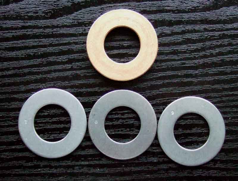 The Workshop Manual shows three washers but only labels two of them - a thrust washer and a floating thrust washer (shim) .052" to .057" i.e. .055" nominal. The Parts Catalogue also shows three washers, but just as part of a king-pin repair kit and not as separately identified parts. The MGOC site shows the main thrust washer ATC4264 but not the shims, saying the shims are only available as part of a repair kit that includes the king-pin. Googling ATC4264 displayed Quinton-Hazell, Brown & Gammons, MGOC and Moss Europe hits. B&G didn't list any other parts, QH listed shims with the main thrust washer but didn't say what axle it was for, MGOC listed the shims as separately available although only for the MGC, but Moss listed the shims indicating they are suitable for both the B and C! The shims are in three different sizes ATC4261 (.052" to .057" i.e. .055" nominal), ATC4262 (.060" nominal) and ATC4263 (.065" nominal) which are selected to obtain the required end-float, the main phosphor bronze thrust washer being sandwiched between two of the shims. But with 0.005" tolerance in each of the three sizes, one could go though an awful lot of them to get the required 0.002" maximum end-play. So off goes my order to Moss for two sets of washers and shims, as well as the bump/rebound stop which I had noticed had lost its bump rubber on the left-hand side. While placing the order online I noticed a checkbox by each item something to do with back-ordering. It was only afterwards I wondered if some or all of the items were out of stock, which is a possibility for things like the shims, much less so for the bump/rebound stop, I would have thought. But in the event they all arrived two days later.
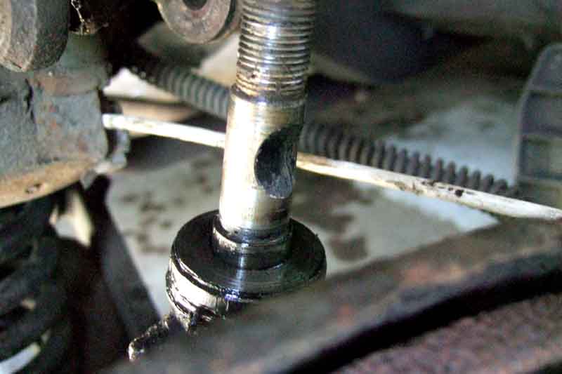 So up goes the front of the car (cross-member on axle stands) and off comes the right-hand wheel. It seems to me that just undoing the big nut on the end of the king-pin will allow the trunnion to come off and reveal the thrust washers and shims, the pin through the trunnion and damper arms is obviously clear of it. However the rubber bushes around that pin fit into a notch in the king-pin, so really the damper arms need to be disconnected from the trunnion and the bushes removed before the trunnion can be removed from the king-pin. And when doing that you will probably need to slacken the clamping bolt that goes through the damper arms. Jack under the spring-pan so the damper arms just lift off the rebound rubbers to take the tension off the trunnion, damper arms and pin before trying to remove the pin. Having replaced dampers and a swivel axle at various times, if I hadn't had that pin and the bushes out beforehand they were seized solid and I had to cut through the pin both sides before I could part them, removing the damper arms clamp bolt and wedging the arms apart meant you can do this without damaging either arms or trunnion. So if you haven't had yours apart before you might like to lay in a repair kit or two (bushes, pin and nut) beforehand.
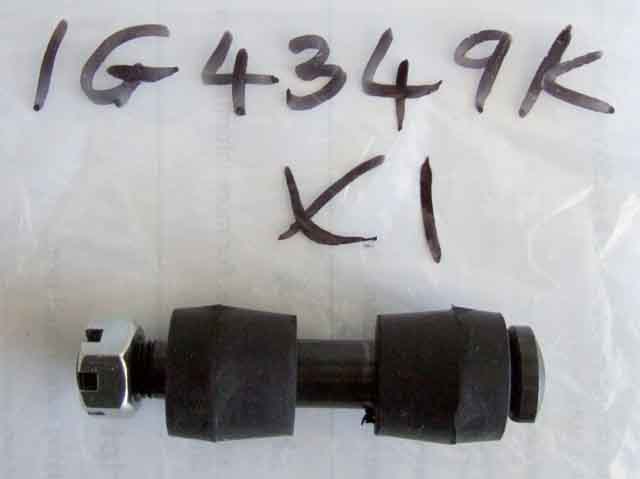 Both top link repair kits I have purchased in the past have been supplied with a Nyloc nut instead of the original castellated nut and split-pin, even though the pin does have the split pin hole. These nuts have been way too deep, so much so that the threads of the pin weren't engaging with the nylon insert and so totally inadequate. If you use a Nyloc at least three threads of the pin are supposed to be exposed, but I wouldn't even trust that as this one pin is all that is holding the top of the wheel up. Fortunately I had suitable castellated nuts I could use instead, and split-pins. At the time of writing MGOC (item 73) say they are supplying Nylocs with this kit, and Motaclan/Leacy say (and show) they supply castellated, so guess which one gets my order.
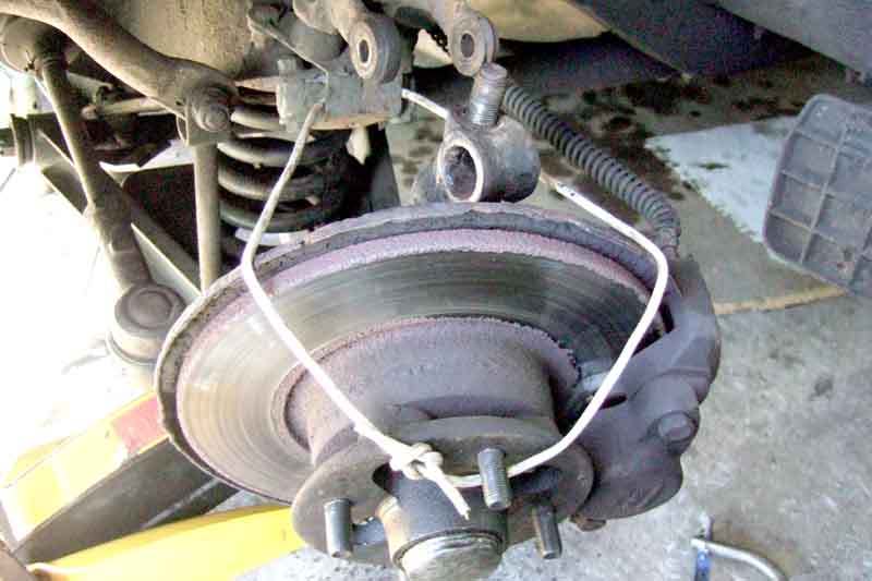 Even then the trunnion could be stuck on the king-pin, so with the nut on the king-pin slackened clear of the top of the trunnion but short of the top of the king-pin, lower the jack from under the spring-pan, and tap the end of the king-pin. Mine are rounded at the top so there was no chance of damaging the ends of the threads, and it came free. Before completely removing the nut jack under the spring-pan again to stop the king-pin and trunnion flying apart. Also have a length of cord available so that when it does come off you can tie up the hub e.g. to the bump/rebound bracket or anti-roll bar drop link to stop it hanging on the brake hose.
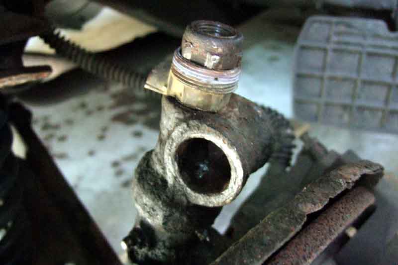 With the trunnion lifted off the end of the king-pin you can retrieve the thick phosphor bronze thrust washer sandwiched between two thinner steel shims. It's now a case of juggling shims, refitting the trunnion and retightening the king-pin nut and checking play. If you have a castellated nut it makes sense here to drop a spacer over the king-pin before fitting the nut so you only have to tighten it a few turns, instead of winding it on and off an inch or more. It's even more important with a Nyloc nut, or you will have to replace that as well, with the number of times you are likely to have to fit and remove it wearing the nylon insert out. If you can't find a spacer that keeps the nylon insert clear of the threads when the nut is tightened, try and find a plain nut instead. To check end-float with each combination as well as fitting the trunnion to the king-pin I slotted the pin back through the trunnion and the damper arms and fitted the nut a few turns (the damper arms with trunnion can be lifted up far enough to clear the top of the kin-pin), lowered the jack under the spring-pan so the tension of the spring was pulling the trunnion down, then lifting and lowering the hub and swivel axle reveals the play. Remember to jack under the spring pan again each time before removing the king-pin nut to try another combination.
And this is where the problems started. The Moss shims came in three bags, two to a bag, with the bags labelled with the three different sizes. The shims were all stamped with a sizing number, and I had two each of three numbers 6 (or 9), 7 and 8 - all so far so good. But when I started juggling shims it wasn't making any difference, which didn't make sense. So I started measuring everything - new washer and shims as well as the old (the old shims had no visible markings) and discovered that my six new shims which were supposed to be two each of three different sizes, were actually five thin shims and one thick! Added to that the new thrust washers were actually thinner than the old ones, at 0.179" as opposed to 0.184", and the old shims were 0.054" and 0.064" i.e. one thin and one thick, and apparently unworn! I suppose the thin one could originally have been a thick or middle one, worn down to exactly the thickness of a thin one, but I find that unlikely. Also I suppose it could have been the top of the swivel axle or the bottom of the trunnion, that bear on the shims, that had worn instead. I tried various combinations, including the new thinner thrust washer plus three thin shims (too thick), but the only combination that came anywhere near was my one new thick shim in place of the original thin shim, i.e. the original (thicker) thrust washer plus two thick shims. This left it with no detectable end-float at all, but the steering did turn freely, and a test-drive did show it self-centres even at the lowest speeds, so in theory is a possibility (but shouldn't be used as some end-float must be present and the suspension unloaded to allow grease to get through the upper trunnion). It's difficult to measure the end-float without a dial gauge, and about the only thing you can do is use a 0.0015" feeler gauge (the thinnest in my set) to check it goes in and leaves virtually no further movement of swivel axle on swivel pin, to get the required 0.002" maximum. As mentioned above with 0.005" tolerance in each thrust washer it's not easy to get the maximum 0.002". The only other combination with the washers I had gave a lot more than a quarter of a millimetre as judged by eye. So a phone call to Moss, who say send them back. Fair enough, but simply picking others out of the same bins isn't necessarily going to be any better. They said they would measure the replacements (really!?) and make sure I got two of each, we shall see. In the event I kept two of the thin ones and the one thick one, just returning three thin ones, hoping to get two medium and a thick back. In the event about a week later I get the correct ones, plus an automatic refund of my return postage, which is pretty good. I swapped one of the thicks for a medium on this first side, but when juggling the other side found only the original combination (a thick and a medium) gave any end-float, so I ended up leaving those in.
July 2021: In an MGOC forum thread on this subject Ben Columb posted a link to an eBay seller of much thinner shims with thicknesses of 0.008", 0.020", 0.040" and 0.060" which hopefully would be enough to juggle with the originals to get close to the 0.002" clearance. Personally I wouldn't go lower than that, only bigger. These have a visibly different ratio of OD to ID than the originals which makes them look more like wheel bearing shims, i.e. either the ID is bigger in which case I can see them sliding out of alignment, or the OD is smaller which wouldn't do that but would give unequal wear on the factory components either side ... or maybe both are different.
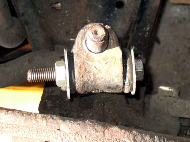 When you have found the right combination remove the king-pin nut for the last time (and its spacer if used), lift off the trunnion and grease the thrust washer and shims by applying grease directly to them at this stage, not from the grease nipple. Refit the trunnion and king-pin nut (but don't tighten it yet), and insert the trunnion bushes into the trunnion. Lubricate the bushes with a suitable lubricant e.g. Waxoyl to make fitting easier. The bushes have to be wedged into the trunnion before you will get them in between the damper arms, even if the damper arms are wedged apart with an old screwdriver between the bosses of the cross-bolt. Use a plain nut and bolt and large washers of a suitable size through the bushes and the trunnion, to squeeze the bushes in to the trunnion. Even so they are unlikely to push straight in between the arms of the damper, I had to turn the trunnion a bit to get one bush started, then a paint-scraper as a sort of ramp to squeeze the other one in while I pushed on the trunnion. Again Waxoyl on the faces of the bushes (and inside the steel sleeves to prevent rusting to the pin in future) and the damper arms makes this easier.
 Make sure you get the trunnion the right way round, the vertical king-pin is INBOARD of the horizontal trunnion pin, not the other way round as is shown in the Workshop Manual and Parts Catalogue exploded drawings!! However the assembled drawing in the Leyland manual is correct, as are both drawings in Haynes. This MGOC catalogue exploded drawing is also incorrect, but the photos of the assembled units are correct. The Moss exploded drawing is also correct.
Peer though the damper arm, tapping it up or down and the trunnion in or out to get the holes aligned on the side the pin is inserted from, then insert the pin, again lubricating it e.g. with Waxoyl. The pin goes in from the front on the right-hand side so the cut-away on the special head engages with the raised portion on the damper arm (from the rear on the left as the dampers are not handed). Once the main body of the pin has started going through the first bush in the trunnion, peer in from the other side and tap and align that as well, until you can tap the pin all the way through. Fit the nut tightening to 40 ft lb, and the split-pin. Tighten the damper wishbone cross-bolt (wedge removed) to 28 ft lb.
With the top link assembled you can finally tighten the king-pin nut to 60 ft lb. Leaving it loose until now allows the trunnion to take up the correct position and be twisted on the king-pin so the holes in the damper arms will line up with the holes in the bushes. Grease the king-pin as normal i.e. from all three nipples using a grease gun until clean grease oozes out of the joints, and wipe off the excess.
And the result? Just the pigging same! However when pushing the car back and fore to work it across the garage to give me more room for the second side I could hear a clonk as I started turning the tyre on the floor. Getting the Navigator to keep doing that while I looked and felt underneath showed no relative movement between track-rod end and steering arm, or up and down or back and fore movement of the track-rod, but I could definitely feel the clonk in them more than in anything else anywhere round the suspension or rack. Wheel off and there is some very slight up and down free-play in the body of the track-rod end relative to the steering arm, and with them parted the pin is flopping about all over the place, so it looks like new track-rod ends for Vee as well.
Lubrication March 2014
As far as routine maintenance goes it's just a matter of unloading the suspension - supporting the body safely with the wheels hanging down - so that grease can work its way round all the bearing surfaces. If it's loaded then it isn't going to get to the surfaces that are passing the weight of the car through to the wheels. You can also work the steering from lock to lock after the initial lubrication, then add a bit more. I remove the wheels as it gives better access from the sides but it can be done without. Wipe the ends of the grease nipples first to avoid pumping dirt in. The fitting on the end of my grease-gun needs to be dead in line with the nipple, or grease escapes rather than going in. Pump till it comes out from under the upper trunnion, and from past the seals each end of the lower trunnion, and wipe off the excess.
August 2018: I've seen mention that angled nipples (UHN445) on the bottom foul something when trying to screw them in. 'A pan' was mentioned but I think they must mean the disc backplate as the A-arms and especially the spring pan are miles away. Even so mine clears the backplate, so theirs must have a longer angled section than mine. The two-part angled as above wouldn't have the problem if fitted in two stages. Depending on how the two threads start the nipple might tighten facing the backplate, or something else that prevents you getting a grease gun on. In which case you can slacken it a little to get the gun on without losing too much grease from the threads, retightening it afterwards. If really anal put a washer on it.
Nipple threads:
Bee came to me with three angled nipples on the right-hand side, which made it awkward to get a grease gun on even on full lock, and as I say above unless it is dead in line grease leaks out from the fitting on the end of the gun. After many years cussing this I finally got round to getting the proper nipples. The angled nipples were in two parts so I could unscrew the business end and get a socket on the hex to remove the base. With straights where they should be now greasing that side is a doddle.
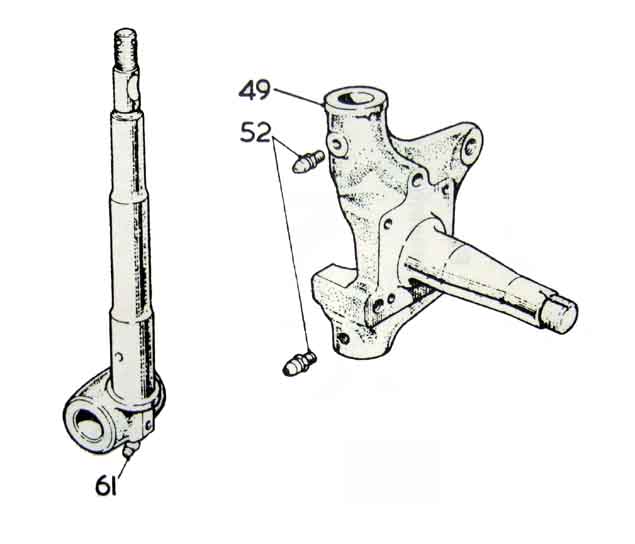 Originally there were only two nipples per side - one at the top of the swivel axle and one at the bottom of the king-pin. But this led to inadequate lubrication at the bottom of the swivel axle so a third nipple was added here. On the right-hand side both swivel axle nipples point forwards, but on the left the lower one points backwards for some unfathomable reason given that one would expect them to be mirror images. The one in the kingpin screws upwards, and should be an angled nipple (UHN 445) to make connecting a grease-gun easier if the car is on axle stands.
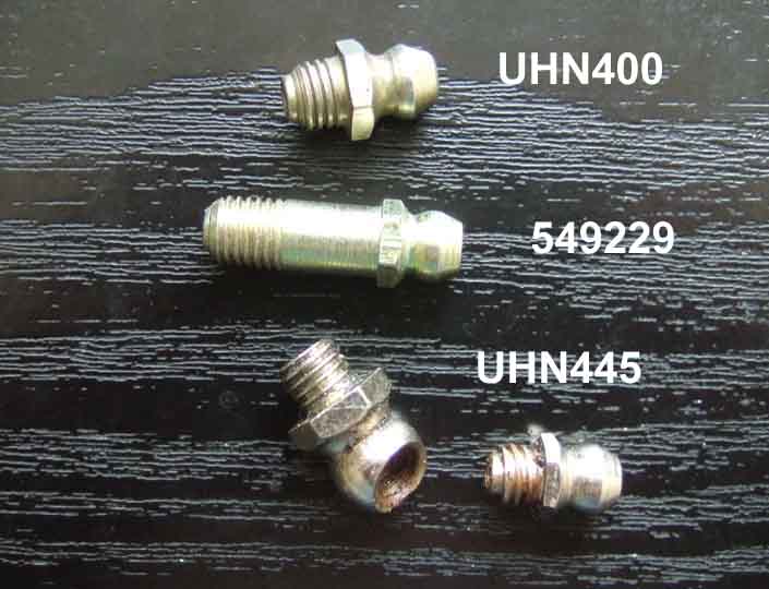 Both the swivel axle nipples are straight, but they should be of different lengths. Although they are usually shown as the same size in the drawings a short one (UHN 400) goes in the top and a longer one (549229) goes in the lower position. This is because the upper one screws into a bulge in the casting so there is clearance for both the grease gun and using a socket to fit/remove. The lower one has no bulge so needs to be longer, and has the hex outboard so again a socket can be used.
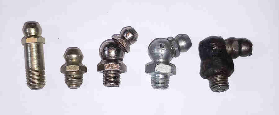 Opinion has it that nipples have different threads depending on where they are used - 1/4 BSF, 1/4 UNF and 1/8 BSP have been mentioned at various times. BSF are described as having a wave-like profile with a thread angle of 55 degrees and UNF are 60 degrees with theoretically flat sides and a flattened crest and root, but in practice the corners are rounded. BSF and UNF have different threads per inch (26 and 28 respectively) so are not interchangeable. 1/4 BSF is the same diameter as 1/4 UNF and both those are the same diameter as 1/8 BSP, that's because BSP sizes are based on the bore of the pipe (usually gas) they are connecting, whereas the other two are the OD of the male thread. 1/8 BSP is 28 tpi so the same as 1/4 UNF, but has a 55 degree thread angle so the same as BSF! BSP can be either parallel or tapered. BSP/UNF and BSF may fit each other over a short distance, mixing any of them will not give a reliable mechanical or leak-free joint, but are probably good enough for grease nipples given that few threads are engaged when fitted and the short/angled ones tighten down to flat faces. Comparing a 1/4 UNF 28 tap with a long nipple by eye the crests of all six threads line up exactly which tends to indicate they are 28tpi i.e. either UNF or BSP. None of the nipples will screw into a 1/4 UNF 28 die at all ... but then neither will the 1/4 UNF 28 tap screw into the 1/4 UNF 28 die! And I think that's enough of that.
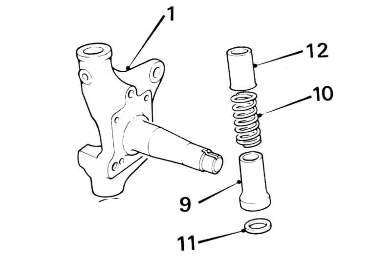 Between the upper and lower king-pin bushes there are two 'dust excluder' tubes, a spring and two seals. The tubes fit inside each other and the spring keeps them and the seals pressed against the upper and lower parts of the swivel axle to retain the grease (more than keeping dust out) which surrounds the king-pin. If you find grease oozing out below the upper bush or above the lower then this 'retainer' has failed in some way. As long as grease comes out above the upper bush and below the lower then lubrication is fine, just wipe this 'excess' off, unless more is coming out there than the bushes!
Rear Bump Rubbers, Pedestals and U-bolts January 2011
Bump Rubbers: AHH9158 for all cars. Just seen a top tip on the MG Enthusiasts BBS from Fletcher Milmore on how to fit new Bump Rubbers, which really appeals to my love of lateral ideas. The hole in the rubber is quite a bit smaller than the peg they are supposed to fit over and people often complain what a chore it is. Fletcher's method is:
Pedestals and U-bolts: October 2016
The pedestal situation is a little confused. The Leyland Parts Catalogue lists nothing for the banjo axle, AHH7335 for tube axle 4-cylinder cars and RB V8s, and BHH1030 for CB V8s (although suppliers indicate this is NLA). Moss Europe and Brown & Gammons to name but two say AHH6053 for banjo and AHH7335 for all tube-type i.e. both 4-cylinder and V8, CB and RB. The CB V8 item in the Leyland catalogue is drawn taller, but as there was only one bump rubber for all cars it seems odd that the CB V8 would have used a taller pedestal than anything else. One V8 Register post says "so for your C/B car you will need the shorter pedestal" but when you look at AHH7335 you couldn't get anything shorter. Only one bump-rubber (AHH 9158) is listed in the various sources for all cars. The Leyland Parts Catalogue specifies U-bolt AHH6452 for the banjo axle. For the tube/Salisbury axle it specifies AHC109, changing to AHH7333 at roadster No. 386795, however the suppliers specify AHC109 for all tube axles.
The only thing you can say for sure is that both types are specifically shaped to fit the axle casing - tapered in the case of the banjo axle and parallel in the case of the tube-type/Salisbury axle.
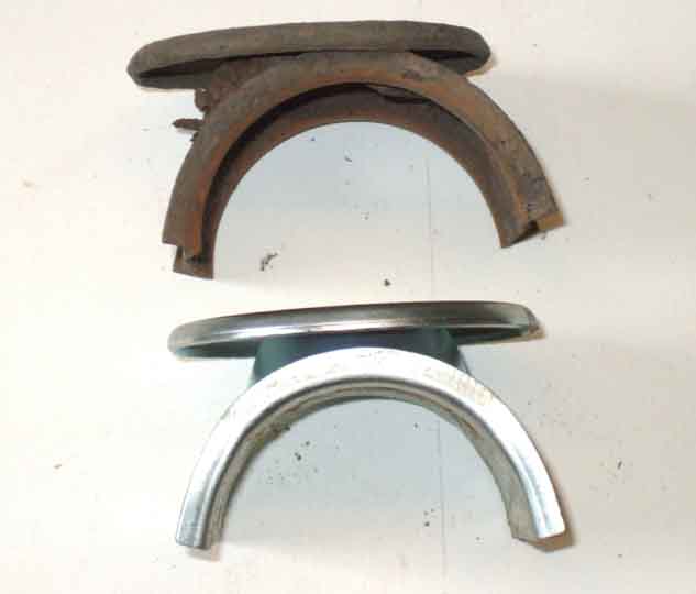 These rot over time, and collapse if your suspension is anything like mine and bottoms over bumps when touring fully laden. If they crumble away altogether you may find the lever-arm damper ends-up limiting axle travel, which won't do it any good at all. I could see one of Bee's had holes and become partially crushed, so ordered a pair (AHH7335 at about a fiver each so not expensive) the next time I was ordering some other stuff. Before starting check the rebound straps also need to be in good condition, and get some in if they are in poor condition. However they have their own issues!
Support the rear of the car securely on axle stands by the rear spring front hangers, so the axle can hang down and give you more working space above. Take the road wheel off.
Jack under the spring to raise it an inch or so. Undo the U-bolt nuts working round all four bit by bit, rather than fully removing each in turn. With the spring supported and raised a bit you should be able to pull the damper plate down off the U-bolts and push it out of the way, also remove the bottom spring retaining plate below the rubber pad (which can remain in place if sound). The U-bolts may need to be tapped up a little to get the two plates off. Check the pads and replace if required.
Tap the bottom of the U-bolts gently bit by bit up to the bottom of the upper spring retaining plate, and wiggle the bolts complete with pedestal out of the plate and off the axle.
 With the pedestal upright swivel the U-bolts through 90 degrees i.e. horizontally instead of vertically as fitted so a straight part is under the pedestal pad, then you should be able to pull them all the way out. If the pedestal has collapsed you may need to exert some force to remove the U-bolts from it by levering the pedestal pad away from the curved section that goes round the axle. If the U-bolts show any thinning from corrosion they should be replaced as well.
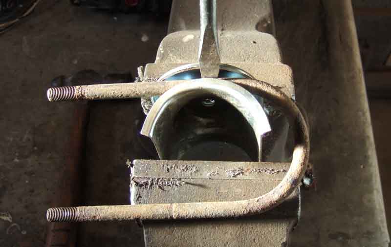 Protect the new pedestal as required. Feed the U-bolts in sideways under the pedestal pad - with chrome bumper pedestals you may well need to lever the pad away from the curved part even on new pedestals to get the end of the U-bolt past the pad without damaging the threads - then turn to point downwards.
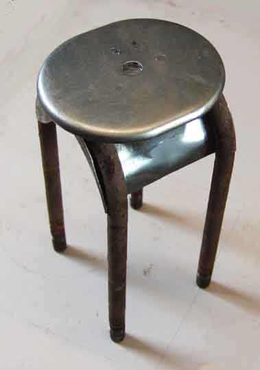 Fit the assembly onto the axle from above. You may find you have to 'spring' the ends of the U-bolts in a little to get them through the upper spring plate. If you can get one end through, put a nut on a couple of threads to retain it while you are pressing the other end in. Without this you may find that as the second end goes in the first pops out again.
With all four ends in, tap downwards past the spring so the pedestal is sitting on top of the axle.
Fit the lower spring locating plate over the end of the U-bolts, again putting a nut on a couple of threads to retain one end while pressing the other end in. The damper plate should fit straight on.
Fit and tighten all four nuts bit by bit working round each in turn once they start to compress the rubber, checking the pedestal is level on the axle i.e. has equal clearance from its lower edge to the guides on the axle. There is no torque for these nuts as typically they will be Nylocs, so you will just have to use your skill and experience to know when to stop. With new rubber pads you may well have to retighten two or three times as they settle. If you find you have rear-end steering as you accelerate and decelerate, then they are loose. Also if you see orange staining where the axle butts up against the upper spring locating plate they are loose.
Alignment
Gaiters
Lubrication
Adjustment/Wear
Replacement Racks
Steering Column
Steering Column UJ
Just a snippet of info as I've seen people asking how to tell the difference between CB and RB a couple of times.
- CB measures pretty close to 440mm from where it exits the rack housing to the end of the splines in the UJ. That is my 73 roadster. There were two chrome bumper 4-cylinder racks for RHD and two for LHD, change point not given just a 'use prior to' comment so they may be interchangeable, possibly just the deletion of the oiling nipple in 1965.
- RB measures more like 570mm. That is from my 75 V8, which the Parts Catalogue says is the same as RB 4-cylinder, with different ones for RHD and LHD. The CB V8 had a different rack again. Likewise 77 and later 4-cylinder cars had a different rack, although according to Clausager this represented a ratio change.
Incidentally the reason why RB are longer could be associated with the different crossmember for LHD RB compared to RHD RB when for CB they were the same. Apparently the rack mounting brackets had to be moved to one side for LHD and the other for RHD, quite possibly because they had to pass through holes in the engine mount chassis bracket which would make lateral positioning important, whereas for CB they passed underneath. If both had to move towards the passenger side of the car, the shaft would have to be longer before it intersected the column shaft for the UJ, the alternative being a re-design of the rack or changing the horizontal angle of the steering column and hence the steering wheel.
Mounting:
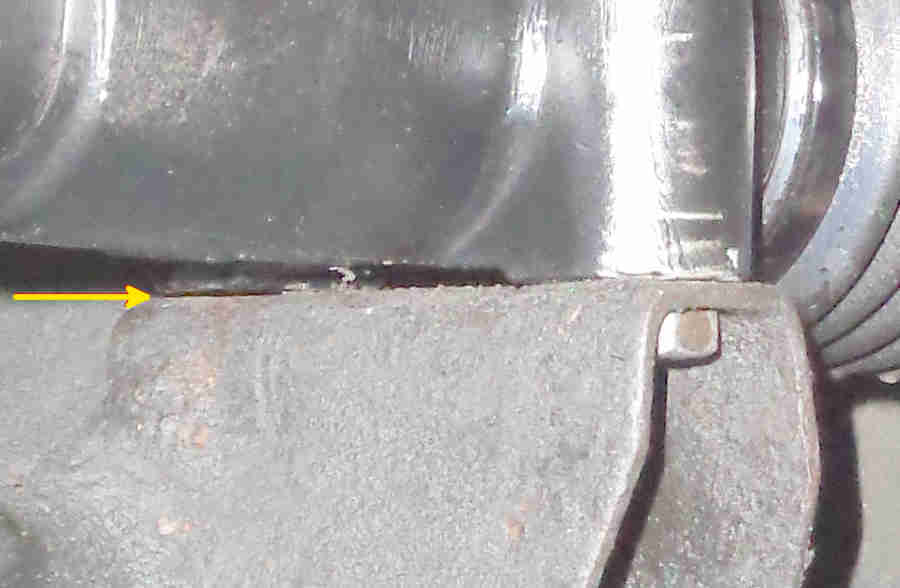 The rack sits on top of the cross-member brackets with two bolts and lock washers and one nut each side. The rear hole has a welded nut inside the bracket so they just use a bolt with lock-washer fitted from the top. Many people assume the front bolts should also go in from the top with a lock-washer and nut underneath but this is not correct - going by my two crossmembers at any rate. That would mean you need a spanner or socket to hold the nut inside the bracket as well as one on the head, but my cross-members have a section of weld on the underside that is shaped to accept part of the hex head of the bolt, and holds the bolt still with a finger-tip while you tighten the nut from above.
Alignment: Three aspects to this - Steering column UJ alignment, tracking, and 'lock to lock' alignment which is getting the same number of turns from straight ahead to either lock, too far one way could stretch a brake hose or cause the wheel/tyre to foul other components.
Rack Gaiters (not 'gators' or anything else!)
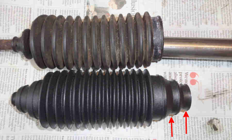 A pair of gaiters I bought seem to be 'universal' in that the big end is stepped to suit three different sizes of rack tube and the smaller two have to be cut off.
To change the gaiters you need to remove the track-rod ends (TRE) and lock-nuts from the track-rods, and it's easier to slacken the lock-nut and get them both moving while the TRE is still attached to the steering arm. Undo the clips or cut the ties and remove the old gaiter. Originally the racks were oil-filled so watch out for that, but even if the gaiter hasn't split the oil is likely to have all leaked out anyway. Fortunately the internal parts should be coated with enough oil to lubricate them for many years. If using cable ties don't over-tighten the small end so the track-rod can be turned for tracking adjustment.
Lubrication: The oil to be used is the same as in the rear axle. Early racks had what looked like a grease nipple in the upper part of the pinion housing, but this was for oil not grease - 'ten strokes of the oil gun but no more' according the Workshop Manual. The capacity is shown as 1/3rd Imperial pint, 0.19 litre, 0.39 US pint. Put too much in and you can burst a gaiter, so if none leaks out between service intervals you wouldn't want to keep pumping more in. However 'old' racks don't seem to be able to keep their oil, changing gaiters on both mine at various times I refilled and it spent the next several months dripping out again, and others have said the same. 'Empty' when I removed the gaiters, but the innards were liberally coated with oil, so I don't think it matters much as long as you keep an eye on the condition of the gaiters.
Without the oiler some talk about removing the damper cover from the pinion, but you would have to remove at least the damper and spring, or the yoke, in order to get oil in while air was coming out. Personally I've done it past the gaiter, and again there are differing opinions. It makes sense to push the nozzle of an oil can through the small end of the gaiter i.e. past the track-rod, but when I fitted new gaiters it seemed a bit tight to me and I didn't want to risk ripping it. So I used the big end, going it at the top, and cupping my thumb and fore-finger round underneath that part of the gaiter to stop it coming out again. With the requisite amount in and the tie fitted work the rack back and fore from lock to lock sloooowly to distribute the oil without bursting a gaiter or forcing it off the tube. Finally, fasten the remaining big end tie or clamp.
For some time replacement racks have been supplied 'grease filled', so no further lubrication should be necessary, and nothing should leak out. When installing a 2nd-hand rack damaged gaiters meant that all the oil had long gone so I decided to pack the pinion bearing and rack gear with grease instead of refilling with oil.
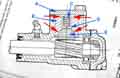 There is a yoke aligning the rack laterally to the pinion with a small clearance, with two different methods of damping any movement within that clearance, and two methods of setting the adjustment of the clearance. Originally there was a damper and a spring inside the yoke. The cover presses down on the yoke, the yoke on the spring, the spring on the damper and the damper on the rack. The clearance is set by shims between the cover and the body - shims originally available at 2.4, 5 and 10 thou. The clearance is set by fitting the cover and gasket 17H6584 (claims there is no gasket are incorrect) without any shims and tightening the bolts until the rack can just be pulled back and fore through the tube. The gap between cover and body is measured and shims to this value plus 0.5 to 3 thou fitted. Despite this clearance the spring inside the damper means that the the pinion doesn't rattle against the rack in normal driving but will absorb some shock over rough surfaces so play could be detected if rack shaft or steering arms are manually pushed hard enough.
 The other adjustment is where the track rods come off the ends of the rack. These are ball joints which articulate, with a sprung seat for the inner ball. The ball housing which fits over the outer ball is set such that the track rod needs a force of 32 to 52 pound INCHES i.e. 42 +- 10, to cause articulation. This could be measured with a spring-balance on the end of the 7" track-rod with a force of 6lb, but having mislaid mine I used a bucket of water! The ball-housing is screwed onto the rack end to give the required force, then the locking-ring is screwed up to the ball housing and has areas that are staked into grooves in the housing and the rack to lock the housing in position. These threads are rather fine, and easy to cross-thread, for example if the housing and track rod are removed to replace the passenger side rack support bearing or bush. If you stuff it up
 although lock-nut 17H8715 is available correction October 2023 although several suppliers show 17H8715 as being for the MGB the Parts Catalogue specifies 17H6574. 17H8715 is for the MGC and although it has the same thread it apparently has a smaller diameter. The MGB item isn't available and neither is the ball housing or spring. However Ultimate Power steering in Australia have a one-piece steering arm and inner joint that seems to just screw on to the rack and is staked in position, it needs no adjustment - expensive though. It looks similar to the one JP Hall in Australia found on his Argentinian rack (with no passenger-side bush!) and had such a job to remove, it seemed to have been fixed with locking compound and not staked.
Wear:
February 2026: At long last it is dry and warm enough to get Bee out on the drive to put into practice a theory I have had in mind for over a year. It's well known that with both front wheels off the ground (and the steering unlocked) by pushing and pulling on one road wheel you can switch the steering from lock to lock. When the MOTers are doing their thing whilst they only waggle one wheel at a time it will be almost impossible not to move the rack itself and hence the rest of the steering system to some extent - and this is where my theory comes in. If the rack itself is locked, say by bolting the pinion cover down in some way so clamping it firmly in the tube, then waggling a wheel can only have an effect on that side of the car i.e. steering arm, track-rod end, etc. So I jacked up both wheels and checked I could still pick up the clonk they have been reporting, which I could. I then slackened the pinion cover and slid a strip of metal between the pinion shims and the rack body and tightened the cover bolts, which has the effect of pushing the yoke down further than it normally does (note that if the strip is between the shims and the cover it will have no effect on the yoke position). I didn't go mad - just tightened enough to make the steering very stiff but still moveable ... and lo and behold no more clonk, from either side. With modern power steering systems is it possible to turn the whole steering from lock to lock like that? If not then maybe the testers are used to that fact and what they are doing is not valid for the advisory it generates. I then slackened the cover bolts, removed the strip, tightened the cover back down (steering now free as normal) and the clonk was back, with noticeable movement of the steering wheel while I waggled. So where is the noise coming from? While the steering was locked I waggled the steering wheel which has always had some movement despite no less than six replacement UJs and even though the latest (a one-piece like the V8 and RB cars that is hopefully better then the original type) has only done 2k and alignment was very carefully checked when fitting it has some play. It amounts to about 3-4mm at the outer rim of the (original 15.5") steering wheel, ideally there would be none but the MOT limit is 13mm so well within that. I was aware of that play when first fitting even though the joint off-car was stiff i.e. it did not flap about, so I don't see what else I can do. Incidentally when the V8 had broken shear pegs in the column and 6-7mm of play that didn't generate any advisory, although I may have been using a different garage at that time. Subsequently I jacked up under one spring-pan so that wheel was clear of the ground while the other had near full weight on it. No noise, and the steering wheel barely moving because the other road wheel was acting as a 'brake' again eliminating movement of the column and UJ. Which why I am contemplating having a test done at a different garage, although I can imagine the previous history of the car will be visible to them.
August 2025:) Prior to the MOT I bought a mechanic's stethoscope and with a pal waggling the wheel side to side there was definitely a click on the near-side (previously the driver's had seemed louder). With the stethoscope on the steering arm a clear click at the rack end but muffled at the track-rod end, so despite the replacement racks and adjusting the locking rings there does seem to be play at the near-side inner joint. Removing the TRE from the steering arm the friction in the joint will barely support the arm plus TRE, so at some point I will have another go, which will almost certainly mean rack removal again. While at it pal rocked the wheels top and bottom as well, more movement on the near-side, and I could see the stub-axle moving relative to the damper arms and upper trunnion so stub-axle bush/king-pin wear. Forcing some grease in stopped the movement confirming it. The MOT confirmed "the usual rack play" (workshop boss comment) plus an additional advisory of 'offside park brake weak' but no comment on king-pins so that can wait for another time.
December 2024: One-piece UJ installed and has no play, but there is still play in the rack shaft. Removed the shims from the damper and bolted it back down to lock the rack ... and now very slight play is detectable in the UJ! That will have to stay - as I wrote about UJs how can they be assembled if here is no clearance and if there is clearance surely that means play? I have the three sizes of shim so juggle them - five thou less and there is notable reluctance to self-centre after a left turn but not right, and a little stiffness is felt turning the steering wheel to the left with the road wheels off the ground. So more juggling and with 2.5 thou less there is still slight stiffness to the left so I go back to the original set. I've not rocked the road wheels from side to side (which is how the MOT place are detecting play at the inner joints) again yet but will do so. If there is play I'll take the shims out and bolt the cover down to lock the rack, and if there is no play then it can't be inner joints! That leaves the pinion, and having fitted two rebuilt racks both the same that will have to stay as well, advisories or not!
September 2024: 'Finally'? Stupid Boy! I get exactly the same advisory as before! After replacing the UJ in November last year in case that was the real cause that is showing play after just 1500 miles (just like the previous four) so I'm no wiser, and I'm going to replace the original spider arrangement with a one-piece AHH6000 - more than 5 times the cost! We shall see.
January 2023: In the end I opted for replacement and what a saga that was - two reconditioned racks which gained the same advisories, a replacement column UJ (which was showing a little wear) and finally seems to have been down to pinion shimming on the reconditioned racks.
August 2022: Advisories on Bee's inner joint play for a second year so I need to investigate. About a month ago with the car parked on the lowered full-length ramps in the garage I noticed a clicking when waggling the steering from side to side, so got The Navigator to do that while underneath I tried to find out where the noise was coming from, but it was inconclusive. During the service with the car further forwards on the concrete floor I waggled and it didn't seem to be making the same noise, so maybe it was the car waggling the ramps in some way. But then trying again on the ground clicking from the front quite noticeably, so given everything it needs closer investigation. First and simplest is to raise the front and disconnect the track-rod ends from the steering arms and see if they are flopping down under their own weight or if there is enough friction from the inner joints to keep them raised. The WSM quotes 32 to 52 lb INCHES required for articulation, but that will be without track-rod ends fitted of course. With them right at the ends of the track-rods that's already some weight and leverage - B&G quotes 0.321 kilos which converts to 0.7lb, and the track-rods are about 8" long. That gives about 6 lb in of force so they should still need quite a bit more to articulate them, disconnected the passenger side just flops down and the driver's side only just holds itself up, so both of those need attention. While the cup seats 17H6571 inside the joint are not available an alternative ACA5246 is shown by B&G. However they show something that looks more like the damper pad ACA5244 than a ball-cup shown by other suppliers (albeit for models other than the MGB). The springs themselves don't seem to be available anywhere I have looked. It may just be a case of lifting up one of the indents on the locking ring and tightening the ball housing slightly, or perhaps putting a spacer behind the spring.
Another test is to see if there is play in the teeth i.e. small movements of the steering shaft can be made before the rack moves. That can be from wear in the damper, if reshimming the top cover takes that out and the rack still turns freely from lock to lock with the wheels off the ground then all well and good. But if it is free in the middle then becomes stiff towards either lock then the teeth are worn and it is terminal. The damper pad ACA5244 is available from some places but not the spring itself, but again perhaps a spacer could be put under the spring in the damper pad.
A third check is of the bush on the passenger side - put the steering at full lock that side, and grasping the gaiter towards the narrower end i.e. round the end of the rack itself see if there is any play. Pushing/pulling fore and aft there is a noise that sounds very like what I can hear when waggling the steering, so probably bush wear as well. The bush/bearing 17H8664 seems to be available, I changed that bush on a Mini many years ago but it involves disconnecting the inner joint which has a very fine thread and is easily cross-threaded.
August 2020: When looking at a squeaking horn brush on Bee I became aware that gentle waggling of the wheel was generating a clonk from low down at the front. Found that to be the wheel sitting on the edge of the front cross-bar on my full length ramps, so rolled the car forwards a bit and tried again. That source was no longer evident of course, but now I could hear a different clonk from the driver's end of the rack. That was the track rod moving up and down as the steering started turning each way, and I could move the track-rod up and down by hand as well. Could be the ball joint inside the gaiter (see previous paragraph), or could be wear at the damper and/or rack. Disconnected the track-rod end from the steering arm and the track-rod was self-supporting so that was OK, which left the other possibility. Hardly surprising, it must be the original rack, but it's worth investigating the damper shims in case it is the damper that has worn and not the rack. Originally three sizes - 0.0024" (17H6566), 0.005" (17H6567) and 0.01" (17H6568), it looks like only the middle one is currently available from the usual suspects. I found four in there with one thick, one thin and two middle so took the thin one out and bolted the cover back down to try it. Completely free from lock to lock i.e. no tendency to bind at the lesser-used ends of the rack, and no more up and down movement of the track-rod, so a good result showing that the wear was in the damper itself and not the central part of the rack. I shall guard that thin shim with my life, putting it in a small poly bag with a piece of stiff card so it doesn't get damaged, for future use if needed. At least it has avoided having to make a decision between a potentially rubbish rebuilt rack and an expensive equally rubbish new one. I could have substituted the now spare thin for one of the mediums and tried again to see if it was still free or had started to bind ... but didn't.
Bee's rack replacement ... X2!
When replacing a rack it's vital to get the alignment correct. This is not a trivial task and involves seating the rack on the cross-member brackets correctly as well as getting the correct alignment of the column UJ. Also to get the TREs balanced on the track-rods to get the same number of steering wheel turns from straight ahead to each lock, which may not be the same as having screwed both TREs on the same number of turns. Finally get the tracking checked.
January 2023: At the time of writing most of the usual suspects seem to list two types - reconditioned where you have to return your old unit and new bought outright with no return of the old unit, with how the pinion clearance is set varying as described below. Both seem to be grease-lubricated which has to be better than the original gear oil.
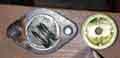 The reconditioned type don't seem to have a sprung damper inside the yoke, instead the spring sits inside the yoke, the cover presses down on the spring, the spring on the yoke and the yoke on the rack. The clearance is set by shims as originally.
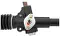 On newly-produced racks bought outright (often described as 'Argentinian') the clearance is set by a grub-screw and lock-nut in place of the usual shims. Probably easier, quicker and hence cheaper than trial fitting, measuring, removal and fitting the required shims. To obtain the same clearance as before the screw would have to be tightened until the rack just started to bind, then be backed off. The amount to be backed-off would depend on the pitch of the thread, which if it were (and I'm guessing here) a 5/16" UNF is 1.058mm or 41.65 thou, and for 3 thou is about 25 degrees, or only 7% of a turn between too tight and too loose! To my mind that needs more care than using feeler gauges and taking shims out of a box, but what do I know?
As a case in point one unit had about 6mm of play between rack and pinion as supplied. On slackening the lock-nut the grub-screw could be turned with fingers, so something very wrong. On removing the cover the spring was in the recess in the top of the yoke which is fair enough. There should have been a washer on top of the spring so the end of the screw could bear down on it and compress the spring and hence position the yoke, but it was underneath. The yoke was free to move up and down, allowing the rack to move right away from the pinion and give masses of free-play in the steering. Refitting the washer with the rack installed and the housing at an angle is tricky as the washer could slip off the spring while fitting the cover. I suggested that if the spring protruded from the housing with the yoke pressing the rack against the pinion, then the screw could be removed and a rod fitted through the hole in the cover, the washer and the spring. Then when the cover was screwed down the spring would be under compression, holding the washer up against the cover, the rod could be withdrawn and the screw fitted. If the spring didn't protrude I think the best thing would be to glue the washer to it.
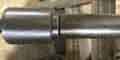 Another problem with these Argentinian racks is from JP Hall in Australia. He says his looks just like the type with the adjuster screw and locknut, but this time instead of the problem being masses of play at the pinion end it is at the passenger end. Taking the gaiters off there appears to be no bush at the passenger end, but there is a circlip as if that is supposed to be retaining one. On OEM racks the bushes were retained in place with a screw. The other thing is that there seems to be no way of dismantling the ball-joints at either end of the rack so that the rack shaft can be withdrawn from the rack tube and a bush fitted. He's faced with trying to fit a split or spiral-cut bush round the rack shaft - and if that wasn't enough the housing in that area is tapered, or scrap the rack. However with using a big enough Stilson's he did manage to unscrew the joint from the rack, although it leaves questions of how the joint is adjusted for correct articulation and locked against coming unscrewed in use.
Other problems with these racks are stiff steering and little self-centring, which can be caused by the pinion adjustment which is relatively easy to resolve, but could be the passenger-side bush or track-rod articulation which is a completely different matter as above. If that wasn't enough one person had two racks from the same supplier where the rack shaft wouldn't line up with the column shaft, even though two old racks did. Bear in mind that with a replacement rack of any type the UJ will need its alignment to be checked and adjusted if necessary.
Removal
Cover or Glove
Alignment
Horn switch
Indicator/turn signal switch
The first wheel had wire spokes in three groups - three spokes each for the ones either side and two pointing downwards in the middle, in a plastic rim with finger-grips on the back. For 1970 it changed to three flat spokes with five holes each, inside a steel rim, padded with dense foam, with a faux-leather covering. According to Clausager this wheel had "three spokes in natural colour alloy", but 'alloy' does not mean 'aluminium' as it does exhibit some magnetism, and what looks like rust spots can develop over time. I don't believe aluminium would have been strong enough, but I also believe 'pure' steel would have rusted very quickly in the UK climate at least. He goes on to say that the UK 'Jubilee' edition had 'black rather than alloy-coloured spokes', and 'alloy-coloured' is not necessarily the same as 'alloy' i.e. it's possible that wheel was painted steel. My roadster wheel did need some light cleaning when it came to me over 30 years ago, more recently I replaced the POs Moto-Lita on the V8 and that needed quite a bit more work, but mainly because someone had used a wire brush across the spokes instead of along their length, and those scratches took some time to reduce to an acceptable level.
I've seen a claim that the V8 had a special wheel with a leather cover, but that isn't borne out by an original brochure (which does highlight differences in trim between the 4-cylinder and the V8) or anything else I have found. The MGC did have a leather cover according to Clausager, and pictures show a double-layer of covering where the spokes join the rim. As that type of wheel had the plastic rim a leather cover for the more expensive MGC is not that surprising. Several pictures of original V8 wheels do not show anything different in that area to the roadster wheel as far as I can see.
In 1973 the five holes (said to have trapped fingers!) were replaced by a tapered slot, but only until June 73 when the slot became simply a depression in each solid spoke, as the slots were found to trap dangly bracelets! For 1977 to the end a wheel with four plastic-covered spokes was used, except for the North American LE of 79-80 which oddly went back to flat spokes with holes again, albeit only three in a smaller diameter wheel. On the 77 and later RHD indicator cancelling is done from a feature on the wheel hub, not a cam or peg on the column shaft, so if you fit an after-market wheel you can end up with no indicator cancelling. However there is a Mountney wheel suitable for 77 and later RHD (and in fact for all RB) that does have the facility to cancel the indicators using two roll-pins, these would be left off if prior to 77.
According to Clausager four different types of column and wheel hub splines were used over the years, and are not interchangeable. See here for the various change points, although it's quite confusing as North American and non-North American diverged at one point. And although Clausager indicates the same hub and splines were used for all flat alloy spoke wheels my 75 V8 has a thicker column than my 73, and although both wheels and nuts fit both columns the V8 wheel is loose on the 73 column taper. The taper means that even with the nut loose the wheel should still be fixed firmly to the column shaft, the taper must be 'broken' as well.
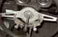 I've seen pullers recommended, a 2-leg works on the slotted wheel, possibly the earlier version with the holes, less so if at all - avoiding damage - on other wheels. Definitely not on the 77 and later wheel as the column is offset from the hub both vertically and horizontally, although a 3-leg may work. Short of that there are two other methods usually employed.
Best to try first is the 'rocking' method. This involves removing the horn push or centre cover (varies with model) and slackening the nut but leaving several threads engaged so that the wheel doesn't suddenly fly off and hit you in the face. Then pull one side of the rim towards you and push the other side away from you, with force, as if you were trying to buckle the wheel, and repeatedly reverse the push and pull as pushing/pulling as hard as you can. This method didn't work for me the first time I took the wheel off Bee or Vee, or a pal's 78, but it has on subsequent occasions.
If that doesn't work this probably will, but needs care:
- Slacken the nut as before but leave it flush with the end of the column - make absolutely sure that plenty of turns remain engaged.
- Sitting in the drivers seat, draw your knees up behind the wheel rim and use them to apply as much pressure as you can to the back of the rim as if you were trying to push it off just with your knees.
- Wearing appropriate eye protection, place a drift on the end of the column shaft (a ball-pein hammer can be used with the ball on the end of the shaft) making sure it is in contact only with the shaft and not the nut or you will damage the threads.
- Strike the drift firmly with a large hammer, perhaps a dead-blow.
- After a few blows the wheel should pop free but be safely retained by the nut which prevents it from flying towards your face, although on a pal's 78 it probably took 15 or 20.
I've seen it claimed that this method can cause the collapsible shaft to collapse. But as far as the upper shaft of the rubber bumper (earlier for North America and applicable to all V8s) full energy-absorbing column goes there is a top bearing with circlips that retains the upper half of the shaft in the outer, which prevents the inner moving in and out relative to the outer, and in any case bracing the knees behind the wheel is going to counteract any downward movement, the shock of the blow releasing the taper. It's possible it could happen on the earlier collapsible column as the whole shaft is free to slide up and down in the outer, but using your knees firmly braced against the back of the rim should prevent that.
November 2019: Just come across this John Twist YouTube that describes this process with just a couple of minor differences dated 2007 ... however this section has been here since February 2000, and I almost certainly had Bee's wheel off this way in 1990. Just saying. He uses three hands but by bracing your knees behind the rim as described above you only need two. He makes no comment about the hammers he uses except to say one is bigger than the other, but the smaller one placed on the end of the column does seem to be a 'soft' hammer of some kind, not conventional steel.
Note that on 1977 (and later) model-year cars the the support bracket for the column switches completely surrounds the column, so in order to remove that you do have to remove the wheel. However the switches are available separately and to replace just the wiper switch you only have to remove three small screws which attach it to the bracket which can be done with the wheel in place.
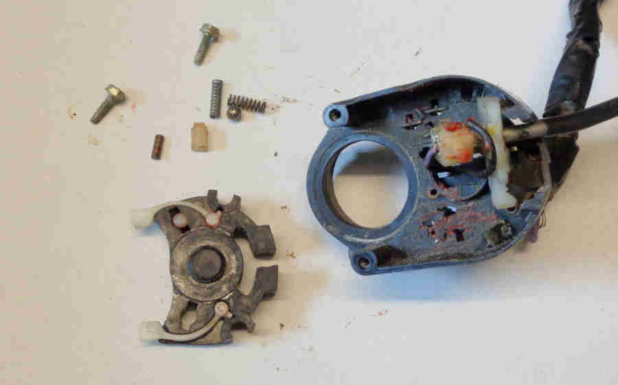 Indicator switches come complete with the mounting bracket which means on the face of it the wheel would need to be removed to replace that. However in theory you could do the much same as for the wiper switch i.e. remove the old switch from the existing bracket, remove the new switch from the new bracket and fit it to the existing bracket by undoing just two screws in each case. But when these screws are removed and the indicator switch detached from the bracket all the innards are exposed including many small parts which can fall out all too easily. Also the screws are behind the hub so not as accessible with the wheel in place as the wiper switch.
March 2017:
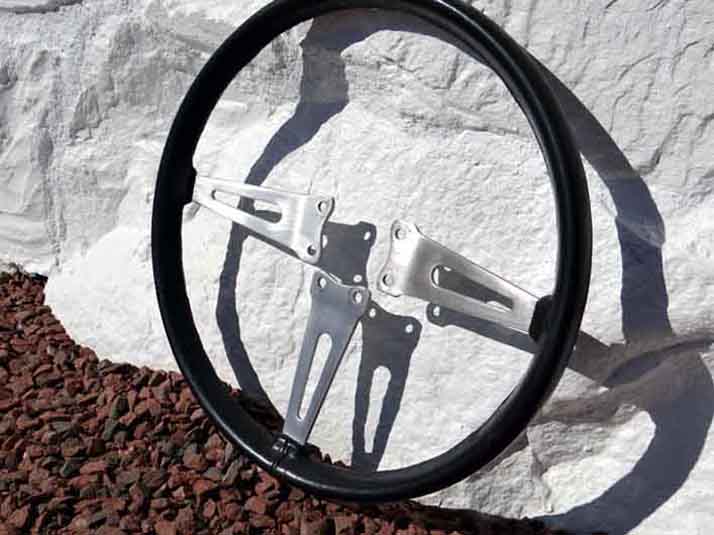 Ray Longsheds wrote saying he was intending to replace his three-spoke wheel like for like, and wondered if this could be done by undoing the six bolts under the horn-push, to avoid any problems of removing the hub from the column. I didn't see why not, so he went ahead which worked just fine. Once off his old wheel showed some distortion in the spokes, possibly due to the alternative removal method above!
Update August 2011:
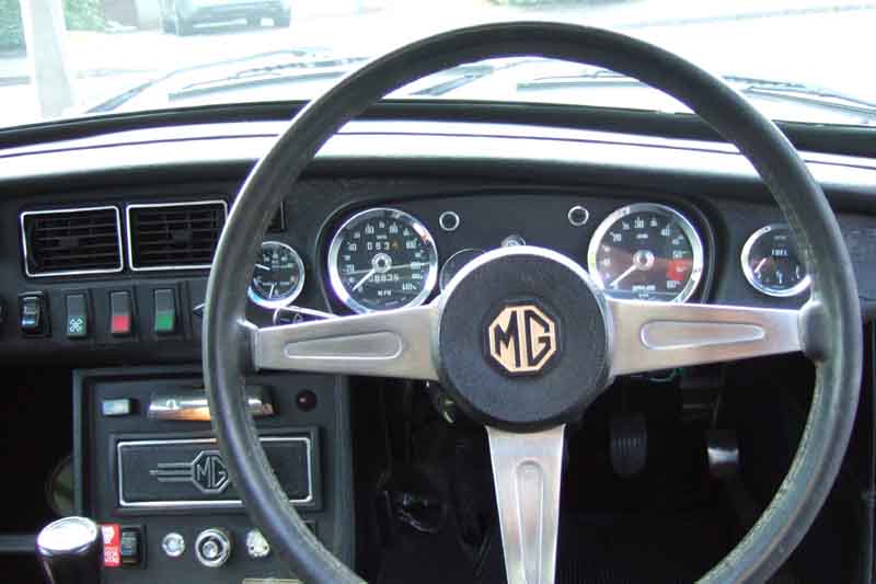 After living with the Moto-Lita on Vee for 17 years and wondering about getting an original, I suddenly decide to do something about it. Contact Andy Jennings and he does have one available at �20 plus p&p. The condition as described and in a photo looks good enough so I go for it, it arrives next day, and if anything is better then expected. First thing is to make sure it fits, which it does. The hub needs repainting which is no bother, the horn-push is perfect, and the rim which is the most important thing as it would be a pain to do anything about is near perfect. The hardest job concerned the spokes, which had obviously been wire-brushed with a drill in the past, but across the spokes as well as longitudinally leaving score-marks in both directions, whereas the original brushed surface would have been longitudinal only. I try modellers wire wool, and various grades of wet and dry up to the coarsest I have which is 400 grit. I manage to greatly reduce the scoring but not totally eliminate it, and even 400 grit leaves the remainder of the surface polished instead of brushed. I even try a hand wire brush on the back (which I'd also done with the 400) in an attempt to recreate the brushed look but it made no impression. I could have tried my grinding stone, but wouldn't have been able to get into the depressions in the spokes, so settle for a wire wool polished finish. Vee is a 75-built car eligible for the gold 50th anniversary badging, so I paint the MG logo on the horn push as shown in Clausager, albeit with Humbrol gold instead of the yellow he describes. Andy couldn't supply a sprung pencil for the horn connection, I could have got a new one but a wire soldered from the back of the slip-ring to a tag on the centre screw of the horn push does exactly the same thing and saves �10. Fitted, it makes the steering even lighter than I was expecting, and at least now I can see the supplementary gauges without peering round the rim.
Cover or Glove January 2021
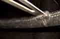 Clausager says that only MGCs had a sewn leather cover over the plastic rim of pre-1970 wheels, in 1970 with the alloy spokes the cover became 'simulated' leather, he doesn't say whether it was stitched or moulded. There is an apparent join of the two ends under the middle spoke, and a ridge round the inner circumference that could be a join of the edges of a strip with what could be sewing holes, but it's not clear if that is stitched or if that's simulated as well.
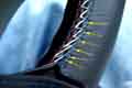 On replacing Vee's wheel I immediately noticed that the rim was slimmer than the Moto-Lita and not quite so comfortable to hold, something I'd not really been aware of when switching between Bee and Vee beforehand. I pondered a leather glove as I'd fitted one to a Mini decades before which made a big difference, looked around but didn't really find anything. Coming up to Christmas 2020 and wondering what The Navigator could buy me I looked again. This time I found a type I hadn't seen before, Halfords had them so an opportunity to see one and they are horrible - pre-formed and clip-on so that was a no-go. Then in January it cropped up on the MGOC forum, and a sew-on cover from 'customsteering' aka mrsteering (which always me think of Mrs Teering ...) was recommended. A bit pricey at �25 for the cover and �10 for the postage. There is a video link on the first site which works, and also references a YouTube video which doesn't work. I didn't appreciate the rap crap sound track but as there is no commentary you can turn the sound off. The edges of the cover are stitched along their length, and apart from the first and last pass of the needle that go through an existing sewing hole in the cover the rest of the sewing is done through every other edge stitch across the gap which results in a pleasing kind of 'cross-hatched' pattern. At least, that is the theory, but in one section of the video the sewing gets further and further out of line between the two halves of the cover, until he skips two edge stitches on one side instead of one to bring them back into line, which is a bit concerning on a promotional video!
The web site is a bit iffy in terms of usability, and the eBay link implies that there is only one size for all MGBs but there were three different sizes of wheel over the years. I queried this and was told to send measurements of the outer circumference of the wheel and the 'grip' circumference (1245mm and 83mm for my 15.5" diameter wheel used from 1970 to 1976 model-years inclusive), and state what stitching I wanted. Both measurements need to be done very carefully - a cloth tape measure from a sewing kit is probably best as it can be wrapped round the wheel circumference quite easily, round the grip circumference with no gaps. If the circumference is wrong it either it will either be baggy or need a lot of stretching to fit, and if the grip circumference is wrong it will either leave a gap between the edges or bunch them up. I left that to soak i.e. pondered it for a bit, and after a couple of days had an email from them offering it Post Free - whether that's always the case or just luck I don't know. Anyway, I ordered one.
It came in a couple of days and needed a little stretching to fit round the rim which is a good thing as it means it won't be baggy and slide about. The included and online video instructions are clear enough except for finishing off each section at a spoke which is a bit sketchy, in terms of getting the knot right by the cover. Maybe consult the person who does the sewing in your house. The recommended "double length approx 1 metre long" for the short sections of rim and 1.5m for the long section are way longer than needed and results in more than half of it being left over, compared to the 6" or so shown in the video. I did wonder whether I had misread and it should have been '1 meter cut off then fed through the needle to make a doubled length of 500mm', but that would have resulted in doubled surplus of 3 inches or so which is barely any longer than the needle so that can't be right. The long run in particular is easy to get in a tangle when doing it sitting in the car - and you do need something to hold the wheel steady while doing it.
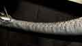 Turn the wheel so the section you are working on is always near the bottom as that is both easier to see and manipulate the needle. Frequently squeeze and wiggle the stitched part as you go to settle it. Both my wheels have a rib on the inside of the circumference which either is, or simulates, sewing (Clausager says 1970 wheels with the alloy spokes had a 'simulated' leather cover) and I position the stitching of the new cover over this. Pull the thread tight from time to time as you go, not too tight though, it's a matter of judgement. At the end of each section I pushed the needle through the back part of the cover not the front as shown, so that the knot will be inside the cover, and because I couldn't get the knot right by the cover I left a little more of a tail than shown which I then tucked down inside the cover at the back of the spoke to keep the knot out of sight. Probably took about an hour of sewing time, plus a bit extra to straighten-out tangles along the way, and I didn't encounter the 'getting out of line' problem which was a relief as either the misalignment or the skipping of an edge stitch would have bugged me.
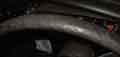 It feels like good quality leather, it's pretty thin though, not like the foam-backed I used on the Mini all those years ago and the circumference of the grip only increased by 4mm from 83mm to 87mm, so not as much as I had in mind. I won't get the opportunity to try it until the weather improves - although ironically the afternoon I fitted it was dry after rain after salt so I could have gone out straight away but I was chilled through by that time. I was anticipating getting one for Bee as well as the rim covering on that wheel has got pretty ratty at the top, probably where the sun has been getting at it for over 30 years. But given the relatively small increase in grip circumference I'm pondering now whether to move it across to Bee's wheel instead of paying a minimum of �25 and maybe �35 for another. Whichever, I'll have to clean my hands after doing any work before driving now!
It took a week before the roads were suitable for a drive and then only just, and it had been getting on for two months since the last decent drive. Despite only being lightly textured it has a significantly different feel to the original smooth surface. At first I wasn't sure how I would get on with it, but half an hour later I was becoming less aware of it. Thoroughly enjoyed the drive, I seem to have missed it more when not being able to drive it because of the weather than when she was off the road for the gearbox rebuild and even for the year going through the trauma of the engine rebuild and repaint.
Steering wheel alignment January 2017 The steering wheel should ideally be 'straight' when travelling in a straight line and not turned to one side which would be irritating, and have the same number of turns lock to lock and there are several aspects to achieving this. Clausager says the rack used prior to 1977 models had a little less than three turns lock to lock, and this can be seen from the vertical spoke starting off pointing downwards from the hub in the straight-ahead position moving to slightly short of pointing straight up at each lock. The 77 and later MGB (not all rubber bumper cars as several sources state) has what Clausager calls a 'lower ratio' rack (and a steering wheel with completely different spokes) but it has about 3.5 turns from lock to lock which makes it a higher ratio and making the steering on those cars lighter than previously, and it makes a noticeable difference to parking effort without a sense of excessive 'twirling' unless manoeuvring lock to lock in a tight space. This rack can in fact be fitted to earlier rubber bumper cars, but not to chrome bumper.
- To correct the steering wheel position itself the most obvious would be to reposition the wheel on the column splines, but that only goes in chunks and you may end up with a small amount of offset one side or the other.
- That can be corrected by turning the track rods in the track-rod ends after slackening the lock-nuts. If you screw one side further in a given number of turns and flats and unscrew the other side by the same number of turn and flats you will keep the original tracking adjustment. This moves the rack relative to the rack casing to turn the pinion shaft, column and steering wheel whilst keeping the road wheels in the straight-ahead position.
- But before doing that - with the wheels off the ground - position the steering wheel on the column so that from its straight-ahead position it gives the same number of turns and part turns - slightly less than one and a half prior to 1977, or slightly less than two full turns for 77 and later - to each lock. Roll the car back and fore (or drive it) on a flat and level surface so the road wheels take up a straight-ahead position. If the track-rod ends are unequal on the track rods then the steering wheel will have turned to one side.
- Now adjust the track rods in the track-rod ends to bring the steering wheel back to 'straight' again. If the steering wheel has turned to the left (anti-clockwise from straight ahead) then to straighten it - with the MGB rack being ahead of the axle and the pinion shaft being below the rack - the rack needs to be moved towards the right-hand side of the car. To do this screw the right-hand track-rod into its track-rod end and screw the left-hand track rod out of its track-rod end. If you back off the TRE lock-nuts then as you turn the track-rods you can count the turns and flats of the nuts making sure you do both sides the same amount each time or you will upset the tracking adjustment and have to reset it. This actually means that both track rods are turned the same way i.e. if grips are used to turn the track rods then to move the steering wheel clockwise both track rods are turned by moving the grips from below towards the front of the car. If you are not sure which way to turn them then do both by the same amount in the same direction and only then see how that has affected the steering wheel. You may have to do this several times to get the wheel correctly aligned, for example three splines of the wheel on the column equated to about three turns of the track rods on my 73 roadster. Don't alter just one of them then look to see what effect that has had or you may forget which way you moved it, do the other one differently, and upset the tracking.
- Making this change at the track-rods will have moved the position of indicator cancelling on pre 1977 cars which is done by a peg or cam on the steering column (on 77 and later the cancelling action is directly from the wheel to the switch so altering the rotational position of the column has no effect). Mk2 cars should have a cam which can be slid round the column to the correct position which is between the fingers of the indicator switch when the car is travelling in a straight line. Mk1 cars have a peg that is screwed into the column which cannot be moved so to correct that you will have to alter the relationship between the column and rack pinion shafts to put the peg between the switch fingers, then move the steering wheel to suit. It seems that all MGB columns have just a notch for the UJ clamp bolt, meaning that the UJ can only fit to the column in one position. In theory the rack shaft has a groove all the way round so the UJ has to be turned on the pinion shaft to correct the column and peg orientation. This is the case on my 73 roadster but on my 75 V8 both column and rack shafts only have the notch, meaning the two shafts and the UJ can only be assembled in one orientation, and the Parts Catalogue indicates that the same rack (BHH1597) was fitted to all RB cars prior to 1977. Several pictures of 'remanufactured' RB racks with the adjuster screw instead of shims show the groove goes all the way round, but one supplier showing a 'rebuilt' unit 77 and later RHD unit (BHH1848) doesn't show a groove, so the assumption (!) is that there is only a notch but on the back out of sight. However these cars should have the sliding indicator reset cam to correct the indicator cancelling position.
- That leaves the column lock, and it's up to you if you want that to engage in the straight ahead or some other position. For the Mk1 column (the UK did not get a column lock until December 1970 but other markets had them from 1962) if you set the peg correctly then you cannot separately alter the position in which the column locks. But for the Mk2 with cam cancelling (or 77 and later) you can change the locking position and adjust the indicator cancel cam to suit. However an irritation with getting the lock engaging with the wheel almost straight is that when pushing the car back or fore in the garage without the key inserted it can lock with the wheels turned slightly - so it won't go back and fore in a straight line! Maybe 10 degrees off is better, by pulling the rack shaft out of the UJ and turning it the required number of splines, then correcting the wheel and (Mk2!) cancelling cam. But not for the V8 as both shafts only have a notch! My V8 steering lock never engaged even if the wheel was turned lock to lock with the key out, except once when I had the column out of the car. My 73 roadster always locked ... until I replaced the column UJ with a one-piece which necessitated moving the column outer in its clamps since when it doesn't lock!